|
"MTX Plus+" -
Architecture
Basis of Design
The aim of this project is to create an updated "MTX", a Z80
based, 8-bit computer, that will be software compatible with
the original, but using the fastest available Z80 processor
(20MHz). Producing a functional, and perhaps even useful (!),
system will involve designing the hardware and creating low
level software to operate it - both elements are breaking new
ground for me and will involve quite a bit of learning on my
part.
Statement of "Requirements"
Perhaps better referred to as a wish-list, some high level
goals that the project should achieve - all very much dependent
on me acquiring the required skills, or finding help, to achieve
them.
- Software compatible with the original MTX computers
- Flexible - able to run in "MTX" and an "enhanced"
mode
- Supporting additional functionality, perhaps including
hard disk/SD card
- Modular - allowing staged development and upgrades
Design Development : "Nice to have" - MSX Compatibility
As I started to work through the design, it struck me that,
with the similarities in the hardware between the MTX and MSX
computers, it may be possible to include a degree of MSX
compatibility in MTXPlus. The major components in the MTX and
MSX are the Z80 CPU and the TMS 9918 (in MSX1) VDP, although the
VDP is accessed through different I/O ports. The systems also
use different programmable sound generators (PSG) and other
peripherals.
Update : The video board has been configured with a
jumper to select the I/O ports used, to be either MTX or MSX
compatible but the MSX sound chip proved to me too difficult to
incorporate at this stage. So, at this point, MSX compatibility
only extends as far as the video board.
Likely Development Phases
| Phase |
PCB |
Main functionality |
|
I |
Bus |
The system will consist of individual circuit boards
for the major modules such as the processor/memory
board and video board, connected over a system bus,
the system bus is described on the
system bus page. |
|
II |
Diagnostic |
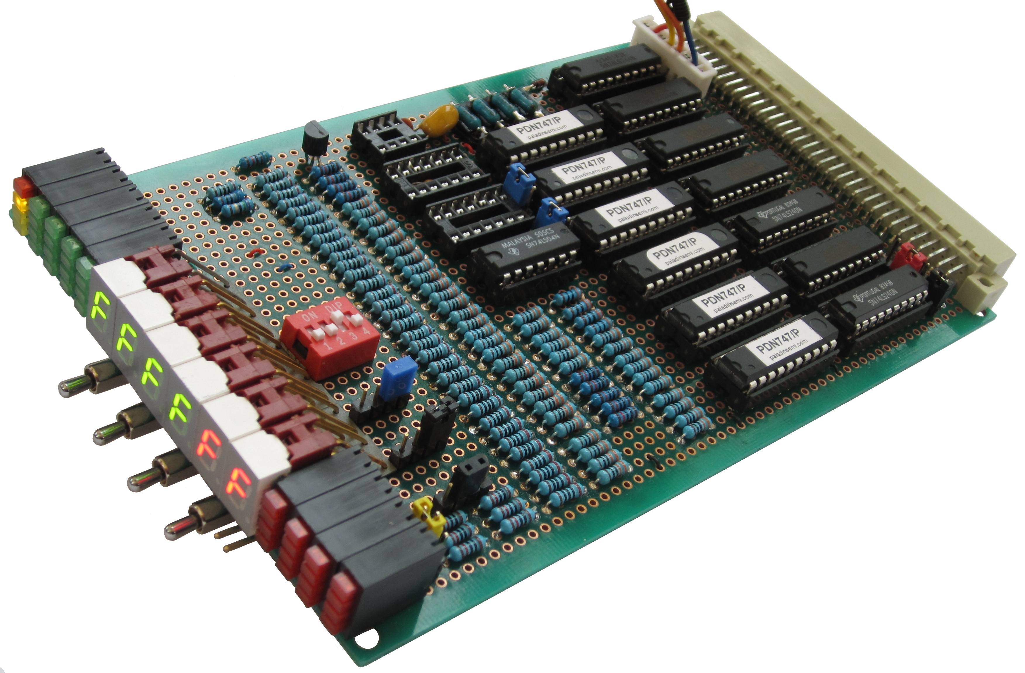
Bus Diagnostic Card
My original plan was to develop the CPU board before
the video board, so in the early stages of
development, there was likely to be an
operational CPU board before a video board was
available and I wanted to be able to determine
whether the CPU appeared to be running "stand-alone"
with no operator interfaces connected.
The MTXPlus Bus Diagnostic Card was designed to
achieve this. |
|
III |
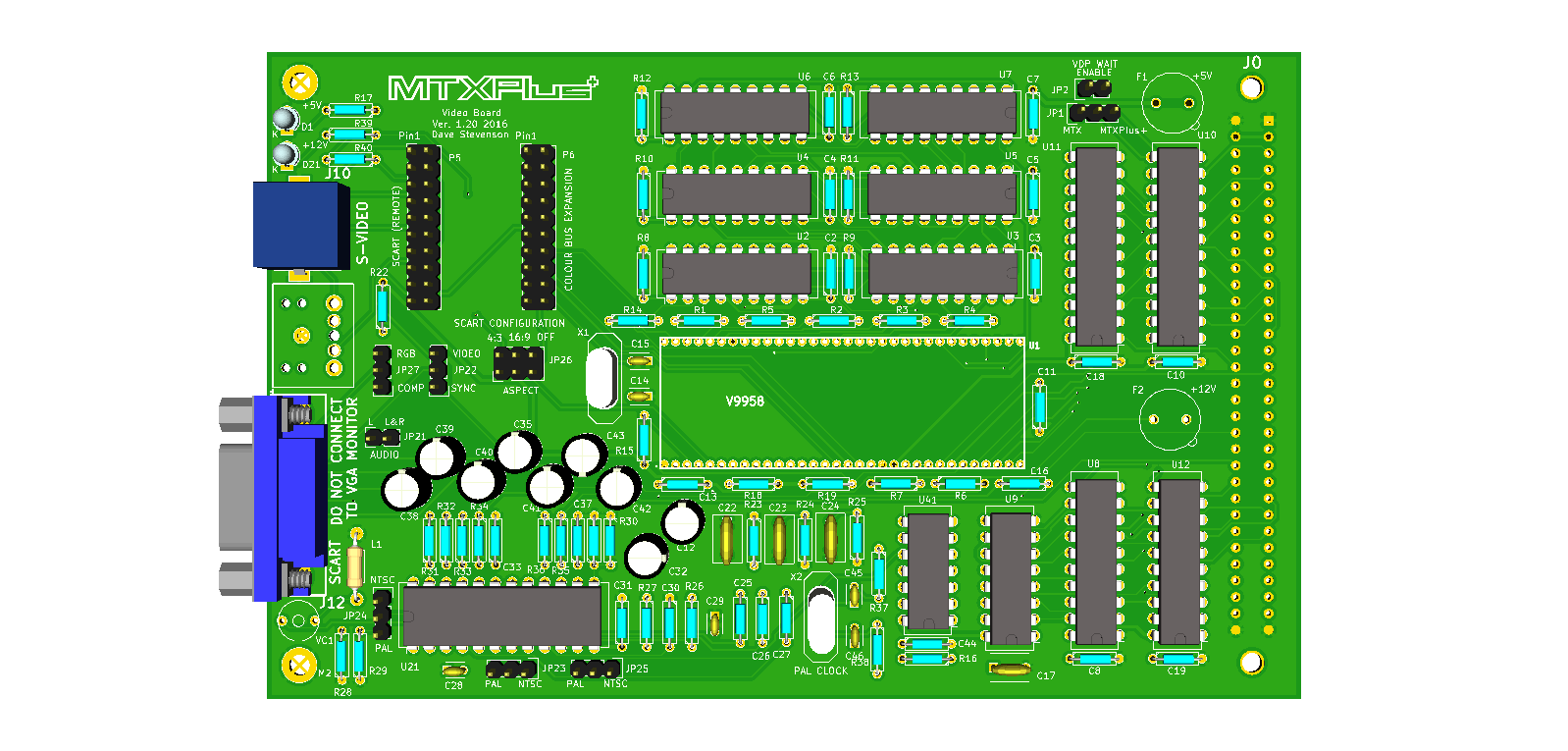
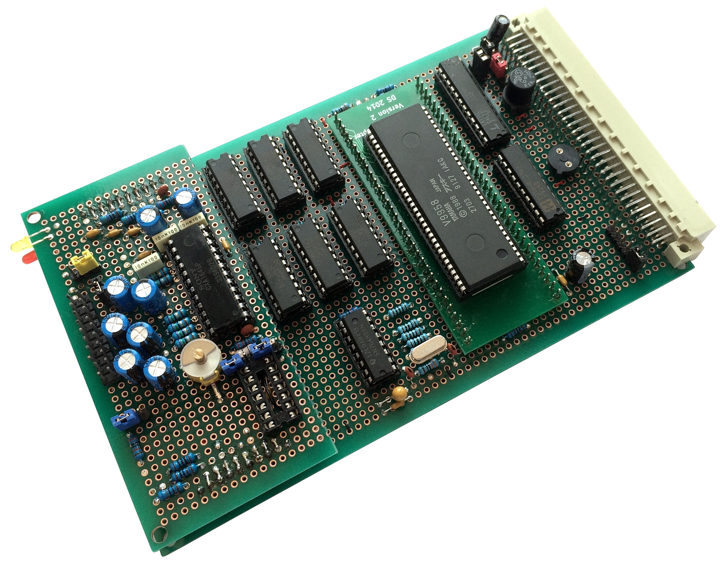
Video |
Video Board - VDP, VRAM, Sound Generator
As Martin and I have created MTXPlus+ to
MTX
interface boards as part of the Diagnostic board
development, we now have the ability (by using
temporary I/O port addresses) to test a video board
on a standard MTX. So, in a change to the
planned development schedule, the video board has
been "promoted" to Phase III and is being developed
ahead of the CPU board. The video board will
contain the VDP, VRAM, video output conditioning and
the Sound Generator. My long term goal is to have a
VGA output from the machine, but the VDP has a low
frequency output that it not VGA compatible. Video
up-scalers are not easy to build, and as I did not
just want to use an external up-scaler like the
HD9800 described on my
MTX Video page,
the output from the VDP will be conditioned to
output RGB signals compatible with the
SCART
interface of modern TVs. In another design
development, the video board output circuit
components will now be installed on a daughter board
- very similar to the original Memotech idea. This
configuration will allow different video
configurations to be developed and tested without
changing the base board design. |
|
IV |
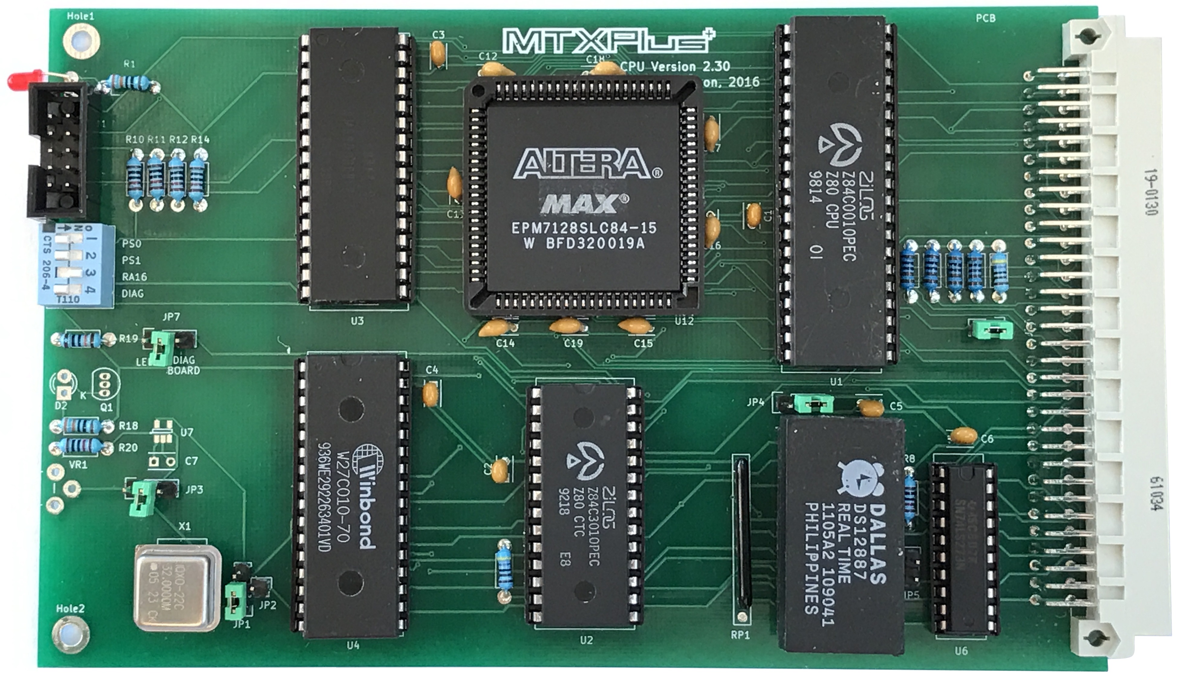
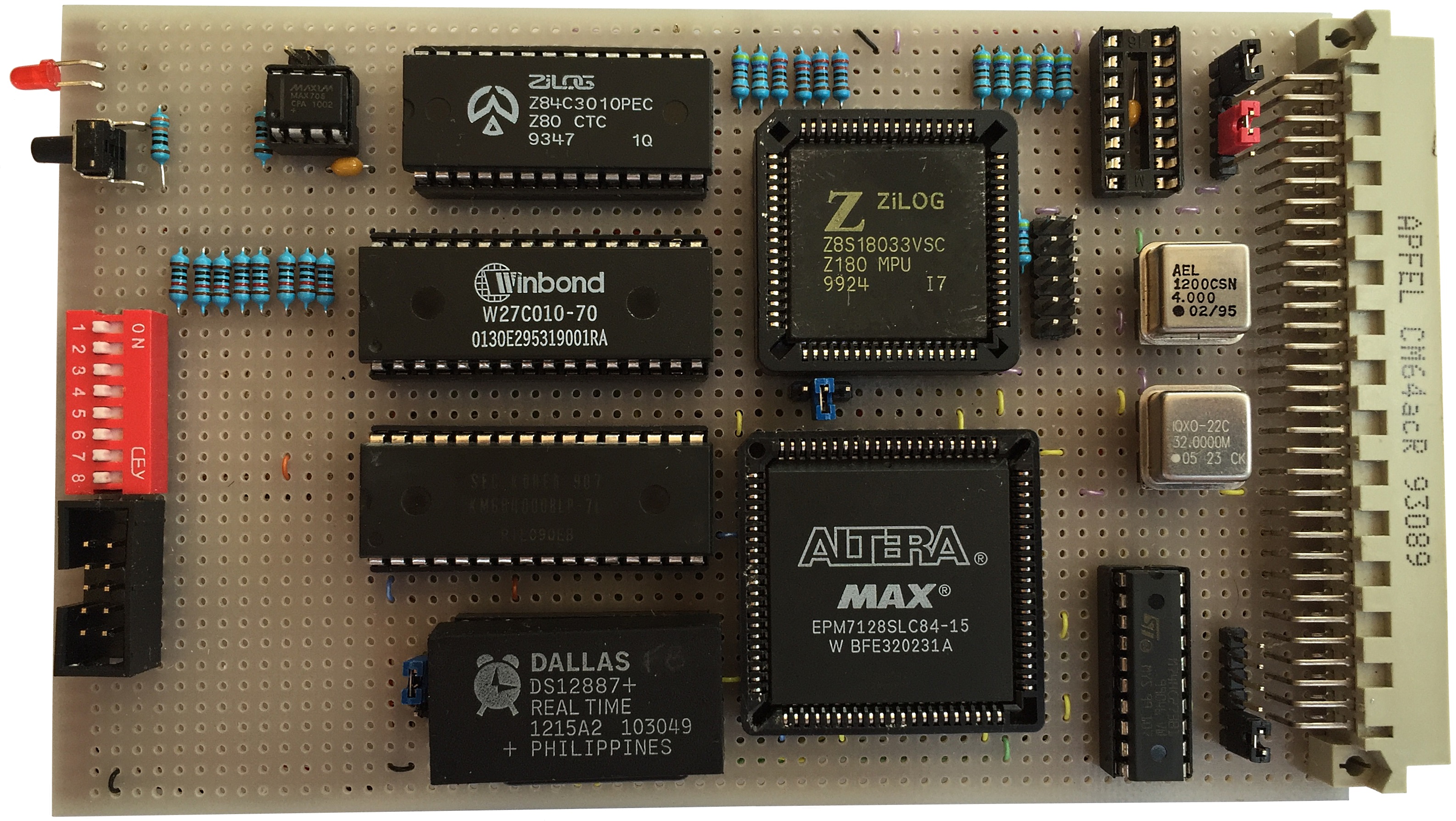
CPU |
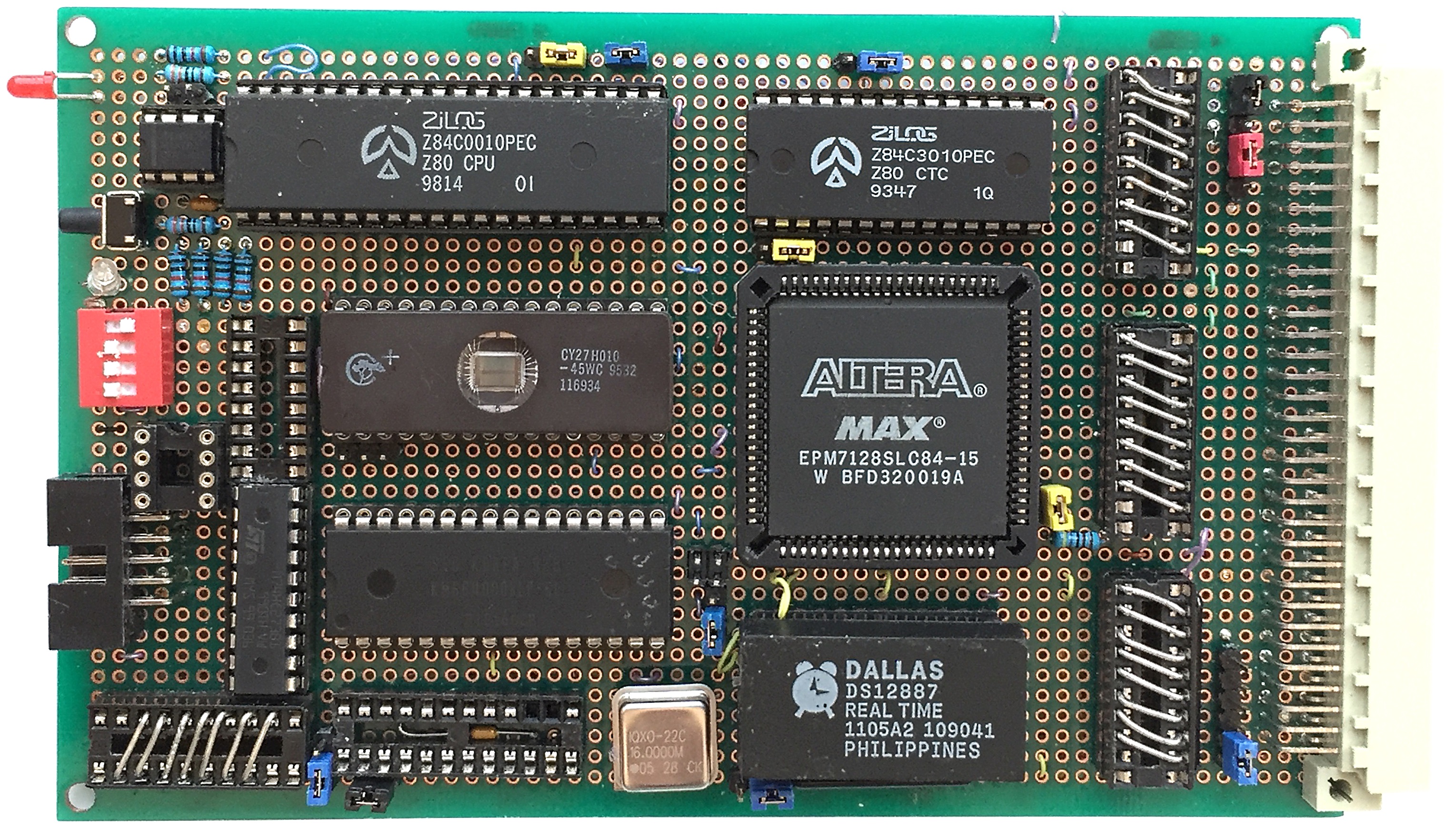
CPU Board - CPU, CTC, ROM, RAM,
RTC, memory decode
logic and a "local" I/O connector.
The intention is to create a Z80 CPU
board with functionality that is as close as
possible to the MTX, to such an extent that an MTX
OS/BASIC ROM can be dropped into the ROM socket and
run MTXPlus+ as an MTX. The features of MTXPlus+
mode will be made available by selection of its own
ROM.
To support this basic
design and to enable testing before the I/O board
was available, I had intended to include an
interface connector on the CPU board that would
allow some minimal I/O to be connected to the
system. The plan was to add a connector to the PCB
to enable "local", i.e., not backplane connected,
I/O to be built for testing etc.
However,
with the video board having been developed before
the CPU board, a considerable amount of testing has
already been possible. There is now little benefit
in including the "local" I/O connector on the CPU
board and it has been removed from the design to
free up the allocated board space. Rather
than the proposed 20MHz, the CPU clock speed will now be 16MHz as
described on the
notes page
Making use of another couple of components from Lez,
the board will also include :
-
A
Real Time Clock using a Dallas 12887, which is a
direct replacement for the IBM/AT
clock/calendar. Martin has proposed that the RTC
uses the same I/O ports (70h & 71h) as an IBM
PC, these ports are unused by any Memotech
hardware and may make it easier to refer to IBM
documentation when programming the RTC.
-
A
MAX705 microprocessor supervisory module to
implement the RESET functions
|
|
V |
I/O |
Base Scope : An I/O board
providing the same basic I/O functions as the MTX, i.e.,
keyboard interface, 2 x Atari type joystick ports, 2 x RS232 ports and a parallel printer
port.
Enhancements : The draft design includes
an
8255
Programmable Peripheral Interface (PPI) chip, intended to be
used to provide an
IDE interface to a
Compact
Flash drive for "mass" storage.
Aspirational : Ideally, it would be possible to build a PS/2
keyboard decoder that would allow MTX type I/O
signals to be fed to the MTX ROM from a PS/2
keyboard. The design includes 2 CPLDs intended to
perform this function.
Once a PS/2 keyboard interface has been built,
and after creating a new OS for MTXPlus+, the enhanced capabilities of a PS/2
keyboard could be used. |
| VI |
GROM |
Games ROM Board, Martin's design for a multi-game
ROM card based on his
original MAGROM design. Although they won't
fit on one of the existing boards, the MAGROM
components do not require a full size Eurocard
board, but the extra space could be used for other
things, for example, a floppy disk controller. |
|
VII |
FDC |
Add a Floppy Disk Controller, with
SDCard support - not required, see I/O Card CF card |
|
X |
Co-Pro |
Originally designed for use with a
standard MTX computer, Martin has adapted his 6502
Co-Processor design to work with MTXPlus+ and kindly
donated the first board to me. |
|
Completed |
In Progress |
In Design |
Future |
|
|
System Overview |
|
To retain software compatibility with the
original MTX design, the upgraded system will need
to be I/O port and graphics compatible with the MTX,
but will also be capable of operating in an enhanced
configuration with a higher processor speed, more
memory and enhanced graphics capabilities.
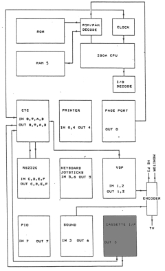
This block diagram is from the
MTX
Operator's Guide and gives a high level overview
of the MTX design, including the I/O port
allocation. I have shown the cassette interface in
grey as, at this point, I am not sure whether I will
implement it and may build a floppy disk controller
instead. Similarly, I will probably do away
with the TV interface and upgrade the graphics
output from the VDP to VGA, but the rest of the
ports will be unchanged, details of the I/O for "MTXPlus+"
can be found on the
I/O Ports page.
|
 |
|
Hardware Design |
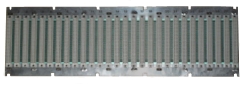
| The system will be based on a
Eurocard type backplane, with individual boards for the
major functions such as CPU & memory, video
processor & VRAM, I/O etc. I bought this used
backplane for £5.00 off ebay for development &
testing the concept, the finished system will
require a much smaller bus - even allowing for
expansion, probably 6 slots at most. |
 |
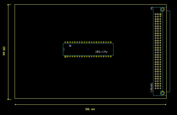
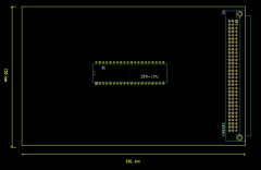
| Having decided on the Eurocard format, that set
the maximum size for each PCB. Typical Eurocard PCBs
for mounting in a
3U
rack are 100mm tall x 160mm deep - my template
KiCad board is shown here, with a 40 pin DIL Z80 CPU
and
DIN 41612
connector dropped in to show scale. If I was going
straight from KiCad to a finished design, I would be
able have quite a high component density on each
PCB, but for development, I plan to use Eurocard
sized prototype boards. |
 |
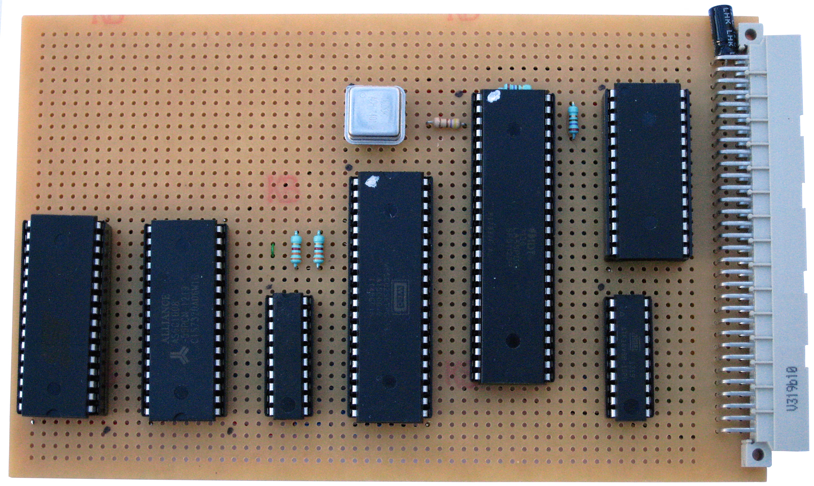
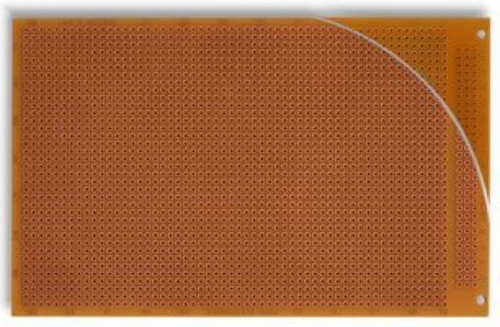
A typical Eurocard prototype board is shown
here, in view of the size of the board and the
potential number of wire links required, current
thoughts are that there will be 3 main PCBs,
populated like this :-
| 1 |
CPU, CTC, System Memory (RAM/ROM) |
| 2 |
VDP, VRAM, Sound Processor(s) |
| 3 |
I/O Ports - Serial, Parallel,
Keyboard, Printer, USB |
Signal allocation is described
on the system bus
page.
|
 |
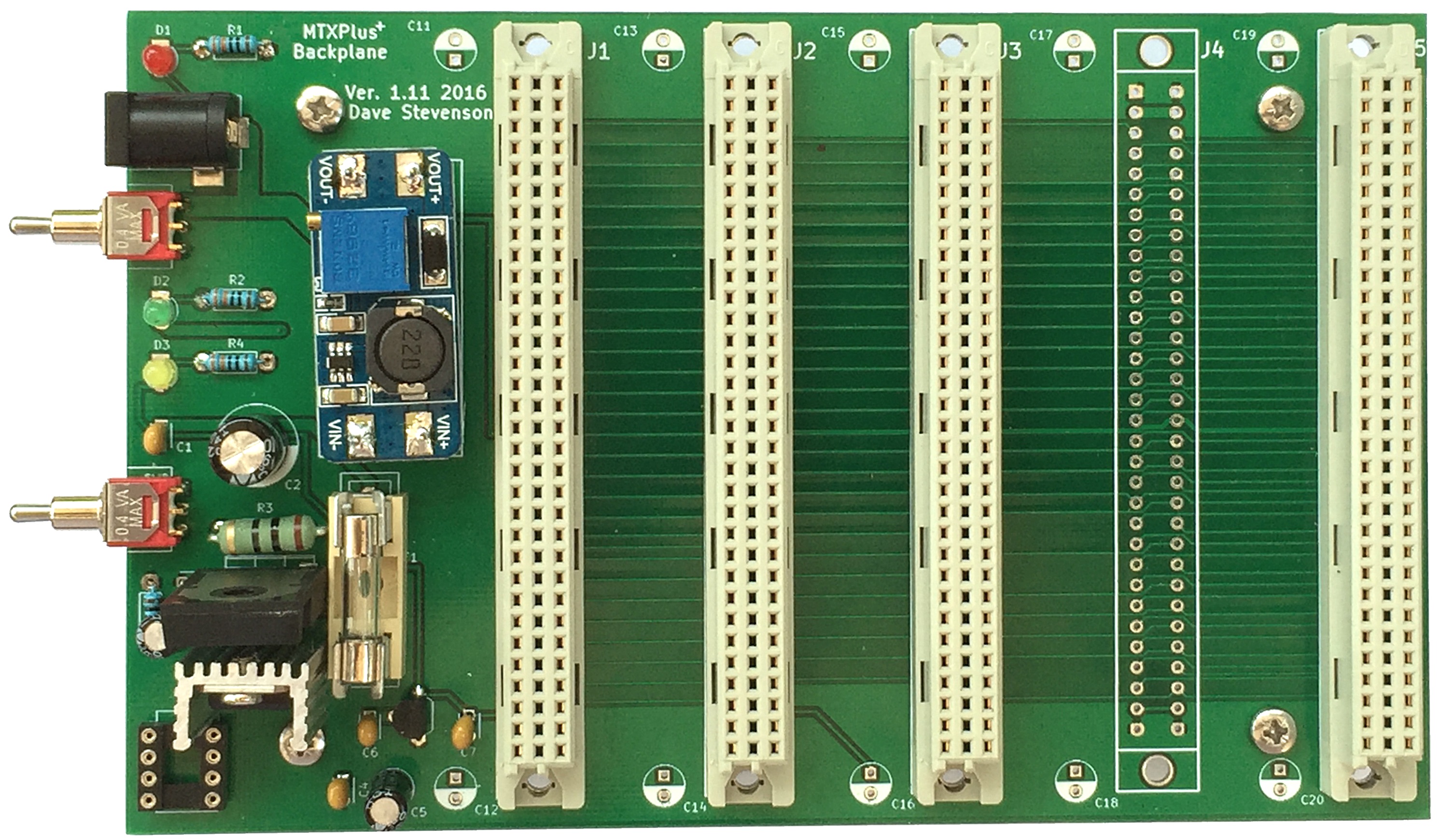
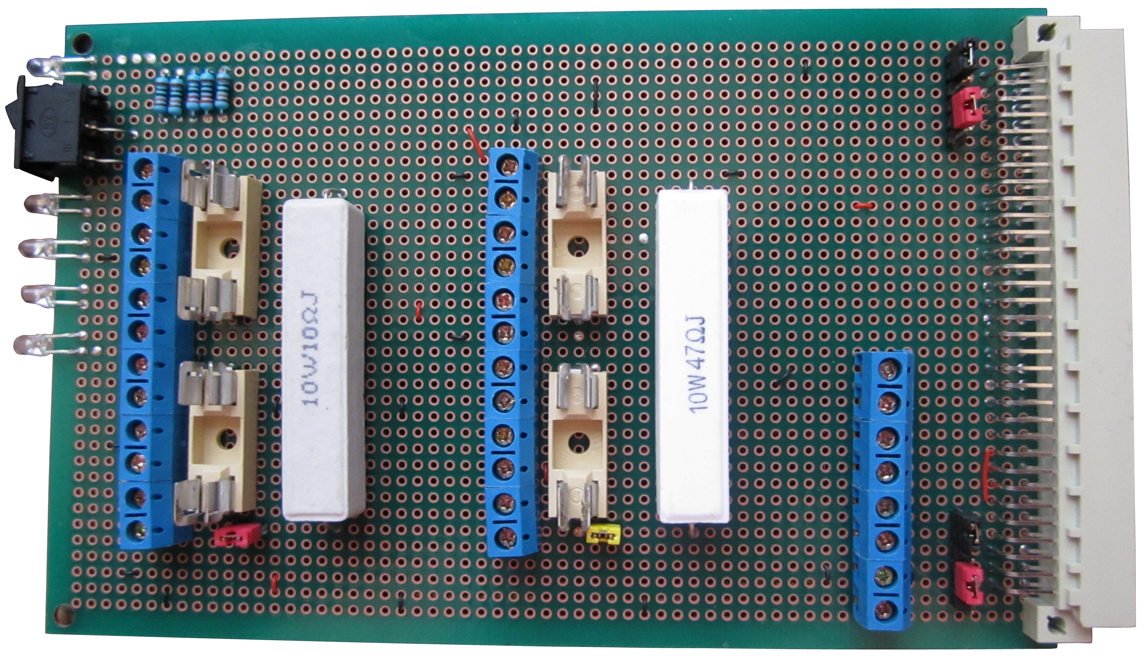
| Power Supply The system backplane will
be fed with +3.3v, +5v and +12v regulated supplies
from an PC ATX style PSU. To stabilise the on board
power, 0.1uF
decoupling capacitors will be connected between
VCC and GND, installed as close as possible to each
IC.
A 100uF
electrolytic capacitor will be placed between VCC and GND,
close to the power input pins of each PCB. The bulk capacitor is intended
to overcome
voltage slumps caused by PC board trace inductances.
To handle noise and fast transients, a 100nF
capacitor will be connected in parallel with the
electrolytic. |

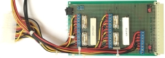 |
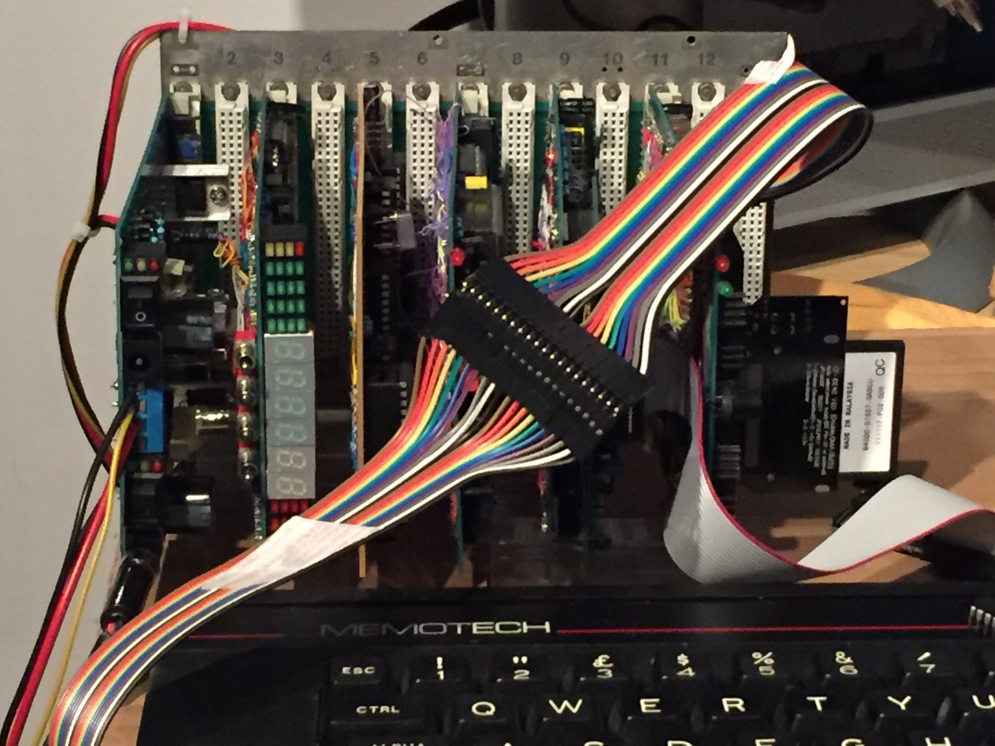
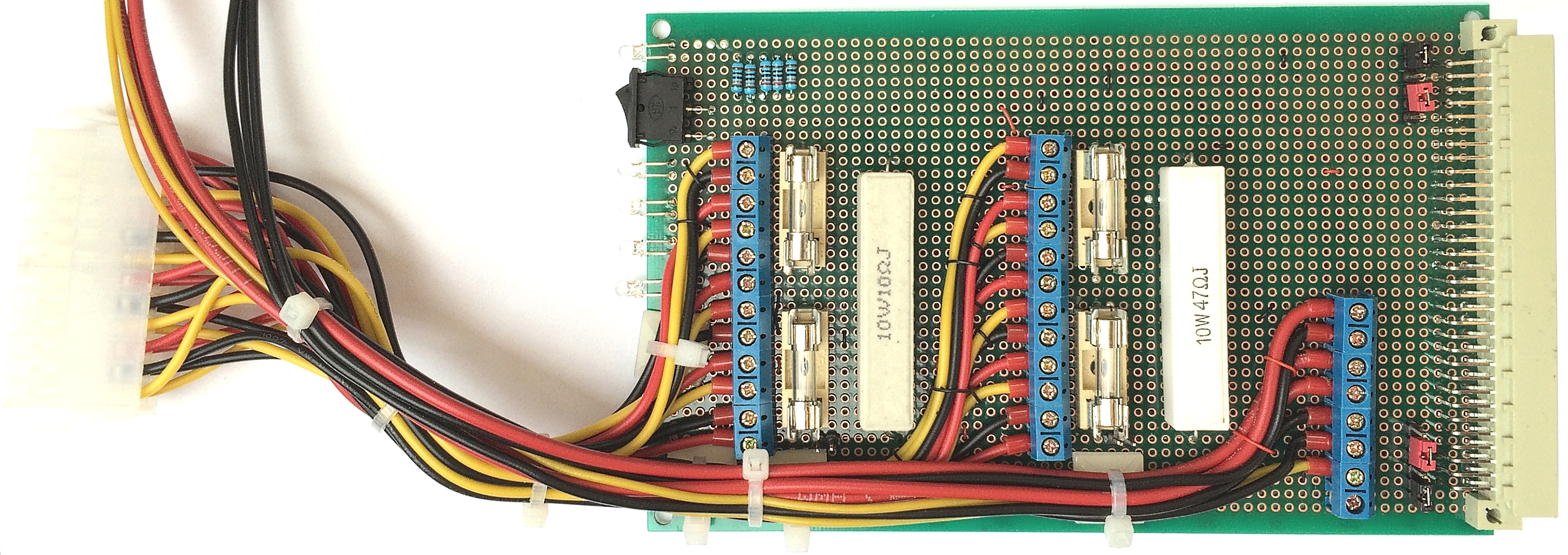
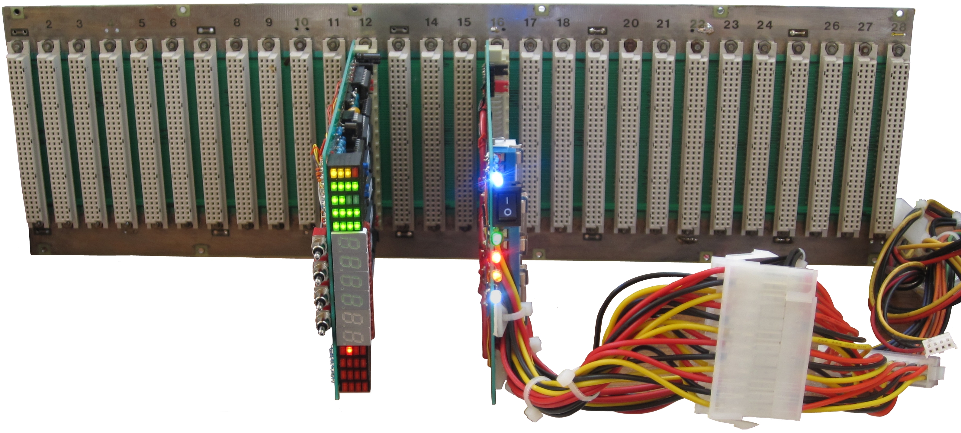
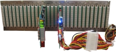
| Here you can see the backplane stood up
vertically with the
diagnostic board and
power distribution
board plugged in and powered up. For initial
testing and use, the backplane will sit flat on the
desk and the cards will stand up vertically from it,
but I need to start thinking of a permanent
solution. |
 |
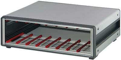
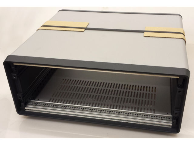
| Since I purchased the backplane, I had been
thinking how I might mount it when (if?) the system
actually worked and had been keeping an eye out on
ebay for a surplus Eurocard equipment rack of some
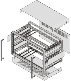
description when I came across this - it's a
Schroff Compac Pro case. |
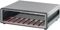 |
| It is not perfect for my backplane as it is only
63HP wide and so I will need to cut-down the
backplane a little., but for the price (£40 after
negotiation) it was too good an opportunity to pass
up.
This is the sellers photo of the actual item, you
should be able to see that the items is brand new -
it is still in the original box with it's original
packing materials. |
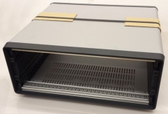 |
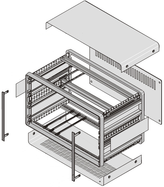
| These are the rest of the parts for the case, I
am not 100% sure that I have everything that I need,
but I am very hopeful. Paying £40 for a less than
ideal box was not what I had in mind, but this now
gives me a secure "home" for the boards as they
are produced.
Since I am not using a standard Eurobus power
supply, this case also has ample space behind the
card frame to install my ATX PSU. |
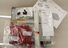 |
| This is the parts breakdown for the 6U case from
the Schroff catalogue. Although not necessarily
true for the desktop case like this, many of the
Schroff and other vendor's, equipment sub-racks have
lots of options available to suit the end-users
requirements.
Consequently, the basic parts kit is very spare
and the kit needs to be built up at extra cost to
build an enclosure that meets your needs. This was
always likely to be a problem when buying a used
rack - it might have been missing essential
components that I needed. Even though I have still
to confirm what is in the box, I think (hope) that I
pretty much have everything that I need and this was
a great buy at the price. |
 |
|
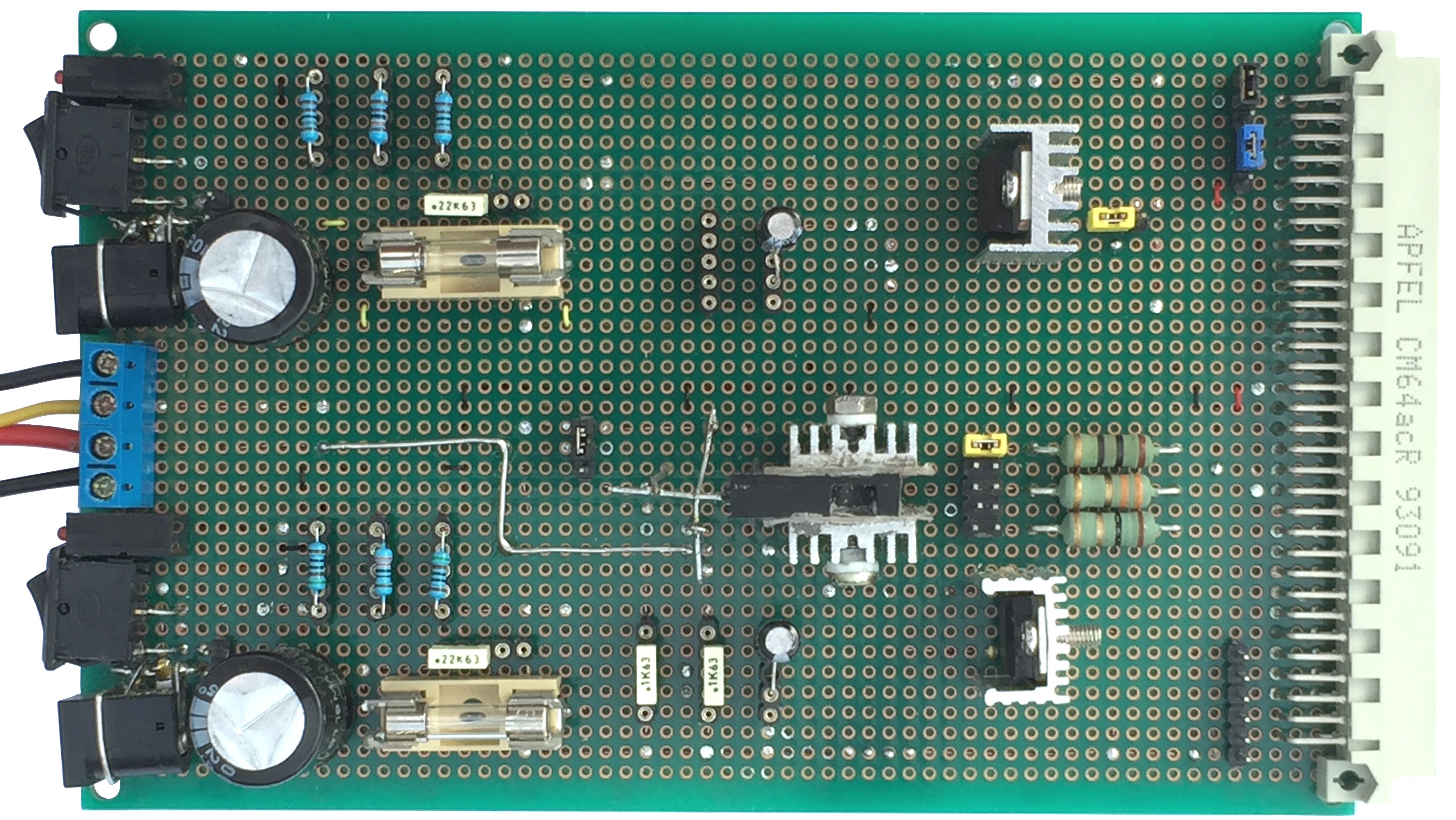
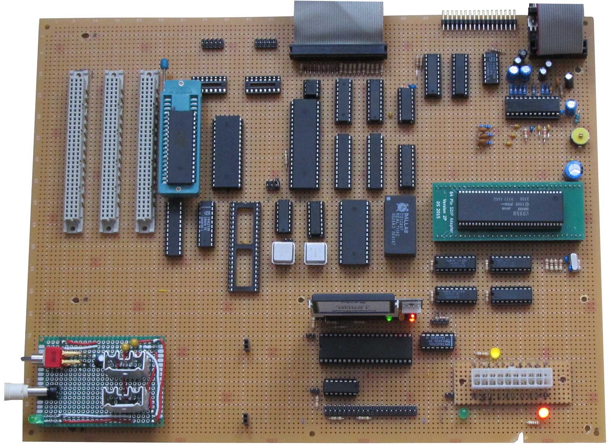
ATX Form Factor |
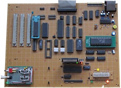
As described above, MTXPlus+
was designed to be a modular system that could be
built and tested in stages with the major modules
such as the CPU and video boards, plugging into a
system backplane.
Once the major modules had
been built and tested, Martin decided that he wanted
to build a complete system on a single
ATX form
factor prototype board and fit it into a PC
case. |
 |
| |
|
| |
|
| |
|
|