|
"MTX Plus+" Power Supply
Superseded by Version 2.0
My MTXPlus backplane has
connections for external power, two VCC planes and two grounds.
I shall be using an ATX power supply to feed power to the
backplane. The easiest method of connecting power from an ATX PSU would have been to remove the PSU multi-way plug and solder
the appropriate wires directly to the backplane. This has a
number of disadvantages :
- It would render the power supply useless for other
purposes
- A switch would need to be installed in a convenient
location to turn on the PSU
- High current supplies would directly feed the
backplane, with the potential to damage the bus in fault
conditions
For these reasons, I shall be building another
card to provide an interface between the PSU and the backplane.
The power module does not actually need to connect to the
backplane itself, but in my case, as there are plenty of spare
bus slots, it is a convenient location for the card. Although
plugged into the backplane, the only signals on the power module
actually connected to the bus are the bus voltage lines and
ground, this will allow the bus voltage status to be displayed
on the power module, but the power lines themselves will be
wired directly from the module to the backplane - not through
the bus interface connector.
|
Backplane Power Supply The
primary reason for creating the power module was to
provide a location to install fuses in the power
feeds to the backplane.
An ATX PSU is capable of delivering
very high currents, typically around 30 amps on the 5v/3v
rails, in the event of a short circuit in the
system, a current of this magnitude is pretty much
guaranteed to damage the PCB and/or the backplane
power line traces.
The first boards to be designed and
built will be the CPU and Video boards, these boards
only require a +5V DC supply, it is possible that
later boards may also need +12V and +3.3V supplies.
Provision has been made in the bus design to
cater for this and, as the PSU has these voltages
available, it makes sense to connect them now. As
described on the
system bus
page, it would have been possible to use one of the
backplane ground planes to distribute a third
voltage level, but instead, pin 17c has been
reserved for the +12V supply. |
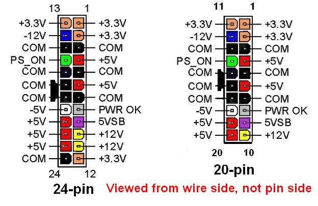
| The images show the pin-outs for 20-way
ATX and 24-way ATX-2 connectors.
(If you are not familiar with ATX PSUs
and how they are powered up, you can find
more details on my
FDX
PSU replacement page.) |
 |
|
| The ATX PSU multi-way connector will
be plugged into an ATX socket with flying leads
connecting to screw terminals on the input side of
the power board.
The power module includes a switch to turn on the
ATX PSU and LEDs to indicate the PSU main and
standby power output
status. Other LEDs indicate the status of the +5V,
+3.3V and +12V lines from the backplane. |
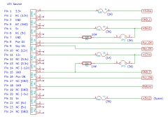 |
| ATX Power supplies are
switched mode supplies and require a
minimum load to allow them to be switched on and to
allow them to properly regulate their output
voltages. The PSU may have load resistors wired
internally, to cater for PSUs that don't, the power
module schematic has a power resistor installed that will
provide a minimum load on the 5v line.
The schematic shows a 10 ohm / 10 watt
resistor connected between one of the PSU's 5v outputs and
ground. This resistor can be enabled or disabled
using the jumper. Some PSUs need the load to be on
the 12v line, therefore a load resistor will be installed on
the 12v line too. The power resistor draws current
from the supply and dissipates the energy in the
form of heat, so the resistor must be designed to
handle the heat generated and are typically
constructed by encasing a wire-wound resistor in a
block of ceramic material.
Load Resistor Power Calculations
A load resistor operating at its rated power will
get quite hot, larger power resistors are often
mounted on heatsinks to dissipates the heat, but
smaller ceramic resistors such as this should be
able to dissipate the heat be convection. To aid
this, the resistor should not be mounted flush with
the board - leaving an air gap will aid natural
cooling. The power drawn by the resistor can be
calculated from the equations :
| |
P = V2 / R |
( P = I2.R
) |
( P = V.I ) |
| Where : |
P = power (Watts) |
|
|
| |
V = voltage (Volts) |
|
|
| |
I = current (Amps) |
|
|
| |
R = resistance (Ohms) |
|
|
| |
|
|
|
| Example calculations : |
| 10 Ohm resistor on 5v
line |
P = 52 / 10 |
= 2.5W |
| 10 Ohm resistor on 12v
line |
P = 122 / 10 |
= 14W |
| 47 Ohm resistor on 12v
line |
P = 122 / 47 |
= 3W |
It can be seen that the same
resistor installed on the 12v line would draw
significantly more power than the resistor was
rated for, to provide adequate load on the 12v
line, a 10W resistor would need to have a value
of around 50 Ohms, the closest standard resistor
value is 47 Ohms.
To reduce the risk of injury to
people or damage to adjacent components, it is desirable that
the resistor runs as cool as possible, using a
resistor of a larger wattage than the calculated
requirement will result in it running cooler.
|
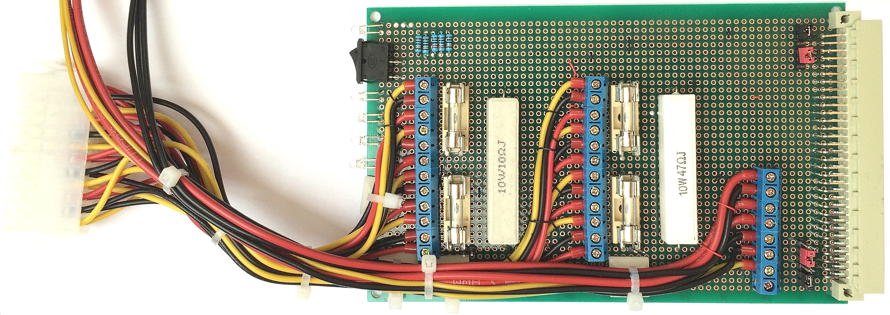
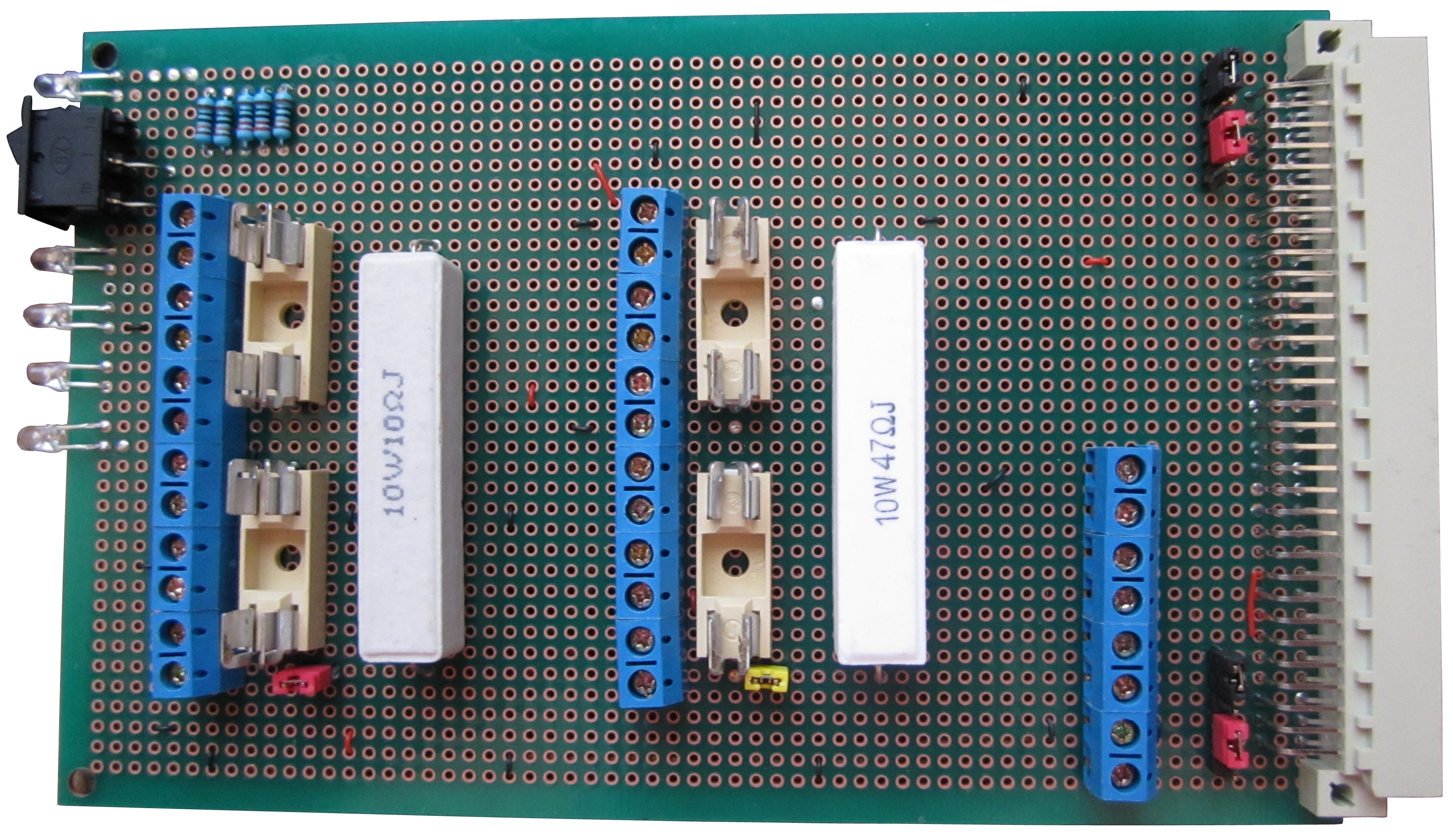
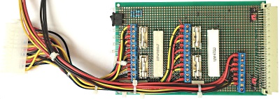
| The assembled power board, the only
thing missing are the fuses. I am also considering
adding some capacitors to the power lines, but as
the boards will have their own power capacitors and
I am using a regulated ATX PSU, I am undecided at
this point. |
 |
|
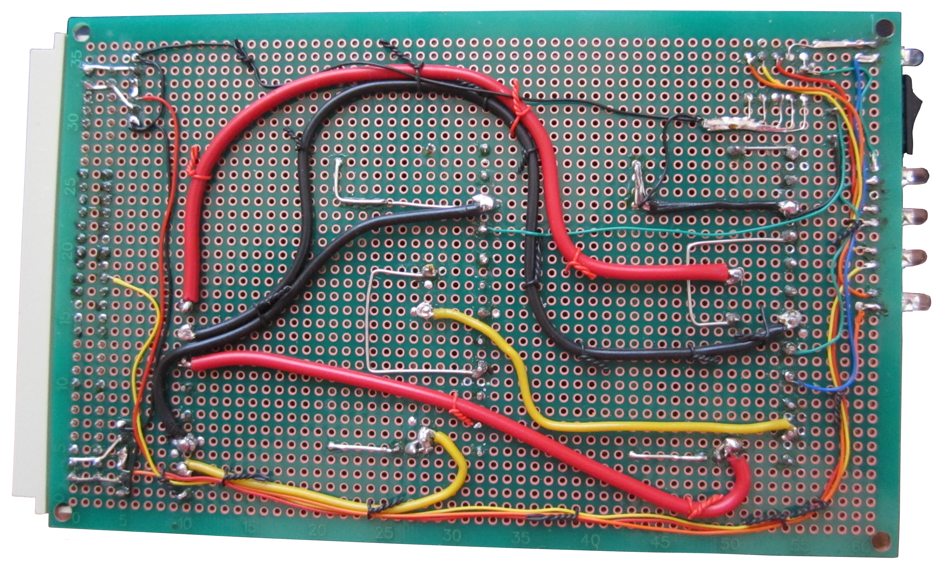
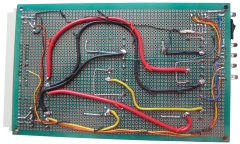
The
solder side of the board :-
|
Wire |
Voltage |
XSA |
Strands |
Rating |
|
Red |
+5V, +3.3V |
0.5mm2 |
16 / 0.2 |
11A |
|
Yellow |
+12V |
0.5mm2 |
16 / 0.2 |
3A |
|
Black |
Ground |
0.75mm2 |
24 / 0.2 |
4.5A |
|
 |
|
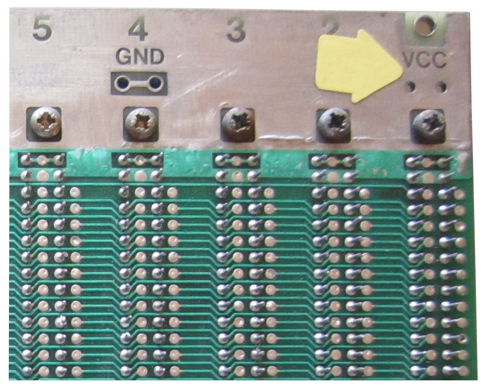
A close up on the rear of the backplane showing a
pair of the power and ground plane connection
points, there are four of these pairs on each of the
planes. On this one, the +5V supply will be
connected to a couple of these points. Similarly,
ground connections will be made on the other side of
the board - you can see the insulating space between
this power plane and the ground connection on the
other side. +3.3V and ground will be connected to
the bottom plane in the same way, and the +12V line
will connect directly to the backplane on pin 17c on
any slots where it is required. |
 |
|