|
 |
The Memotech MTX Series |
 |
SDX
 |
 |
| |
|
|
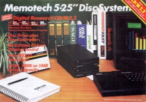
Original Memotech "flyer" for
the SDX |
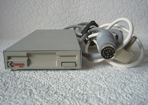
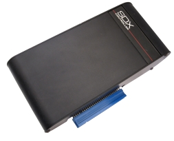
SDX Controller from ebay.de |
The SDX System
The Memotech SDX was
the successor to the high cost
FDX disk system, the
first version of the SDX consisted of a disk controller board
fitted inside a brushed aluminium case with the same profile as
the MTX, connected to the edge connector at the left hand side
of the MTX. Originally supplied with either one or two 5.25"
floppy disk drives, the controller could also be used with 3.5"
drives in place of the 5.25" ones. A later version of the SDX had a
single 3.5" floppy drive built into the controller module, which
again connected to the MTX edge connector and could support a
512kb RAM/Silicon disk.
The original SDX was available in two versions :
- SDX Disk BASIC - Added disk functionality to BASIC
without requiring additional hardware, other than the SDX
- SDX CP/M Package - Added full CP/M functionality,
requiring the addition of an internal
80 Column board
to the MTX
I bought an SDX controller from a seller on ebay.de in
March 2013 and had it shipped from
Germany to the UK. It was one of the original versions of the SDX
and would originally have been supplied with either
one or two 5.25" floppy disk drives. The drive originally
supplied by Memotech also had a 5VDC output from its power supply to provide
additional power to the SDX controller - there not being enough
power available from the MTX PSU.
This SDX disk controller
board originally supported a number of Memotech disk types,
including, "03" (500k/320k) and "07" (1MB/640k) disk
drives. These disk
types have the same geometry as 3.5" disk drives, so I decided
that a 3.5" disk was more desirable for my SDX than a 5.25".
NB: Memotech did not adhere to
the usual convention for the orientation of the drive
ribbon cable. Usually, Pin 1, denoted by the red stripe
on the cable, and all other odd numbered pins, are
connected to ground. On the SDX, the even numbered
pins connect to ground, this means that the red
index stripe on the IDC cable for the floppy drive
must be connected to Pin 1 at either the controller
or the drive(s), but not both - one or the other
must be reversed.
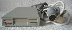
| Since the controller was sold without the disk drive, I needed to
source a powered drive that could also supply power to the
SDX controller. I already had an external, mains powered 3.5"
disk drive for my
Atari 520 STFM which seemed like a good choice
for the SDX too, a Cusana Model CSA 354. |
 |
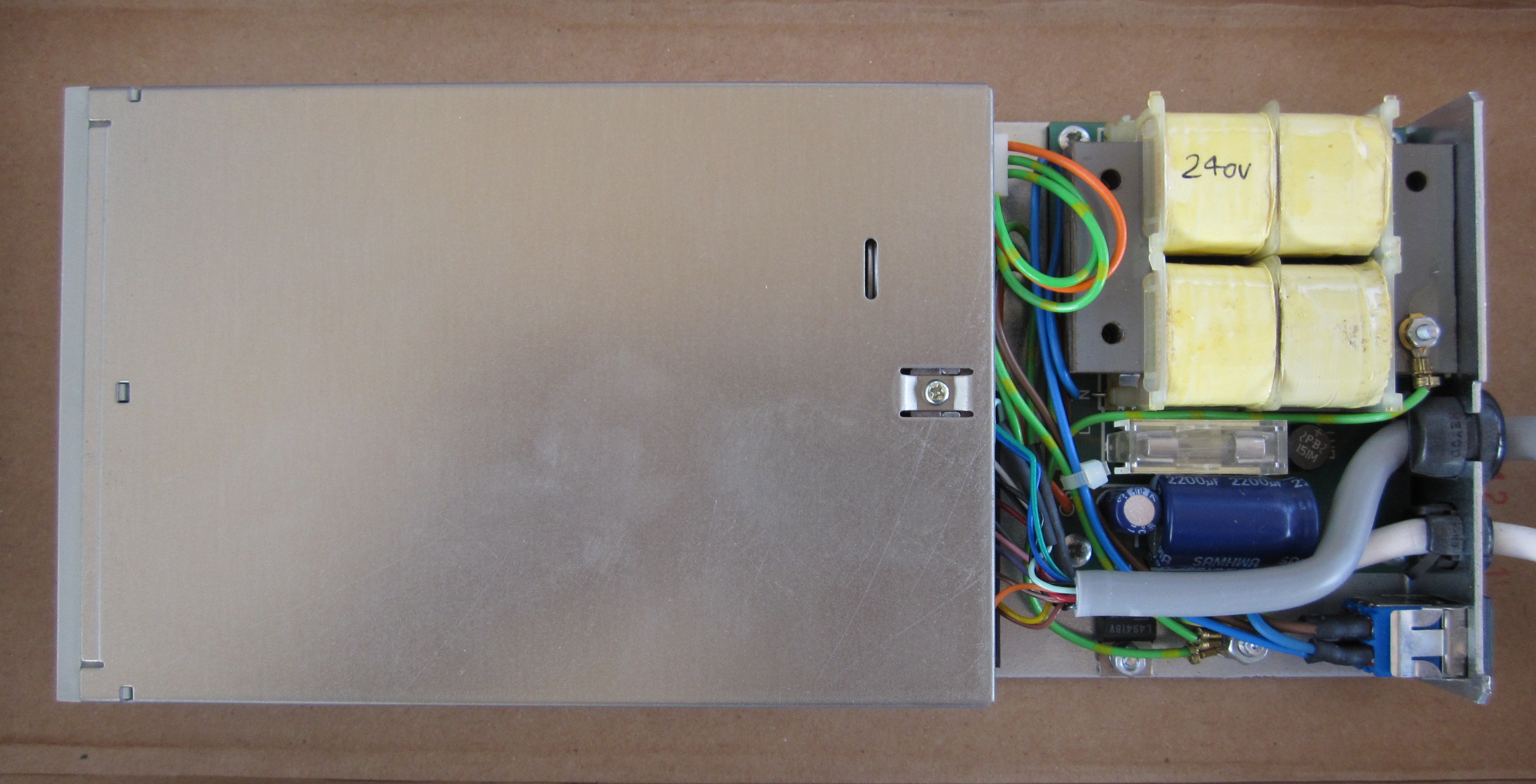
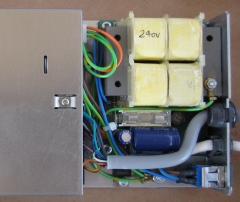
| As luck would have it, there was an identical
drive for sale on ebay while I was waiting for the
controller to arrive, so I bought it. Here is a
photo of the
inside of the drive, showing the 240VAC PSU, the power
switch and the round data cable which connected to
the Atari ST. You can see that the rear panel at
the bottom right of the picture already has a slot
cut out that will make it easy to get the ribbon
cable out of the case and the 5VDC power cable for
the SDX can exit through the opening for the ST data
cable. |
 |
| I believe that "normal" 3.5" disk drives require
modifications in order to use them with an Atari ST,
so rather than mess with this drive, I decided to
keep is as a spare for my ST and use a PC drive that
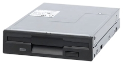
I was confident would work with the SDX. I chose a
Sony MPF920 which I had already proved to work with
my FDX disk controller as a Type "07" drive. |
 |
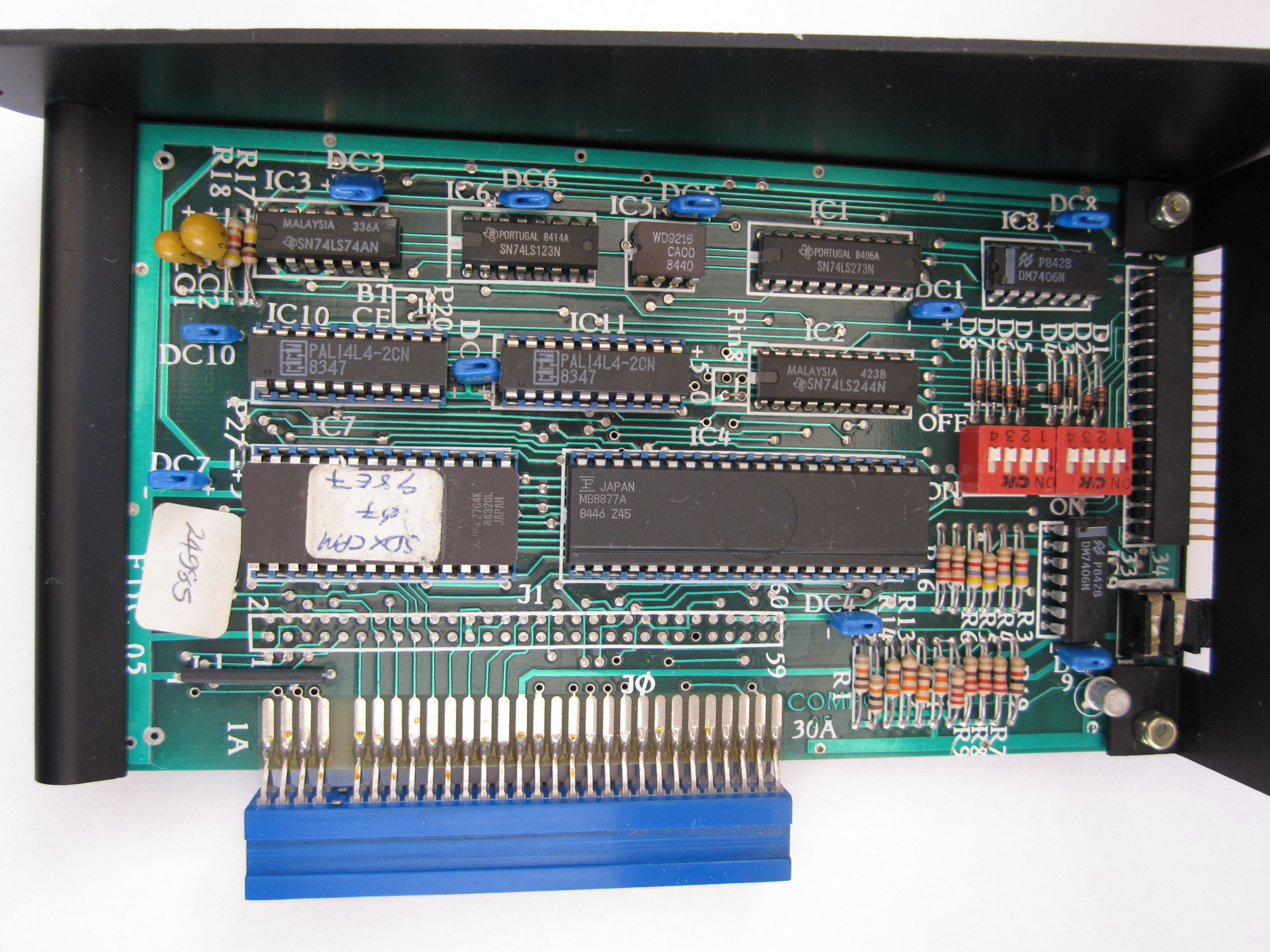
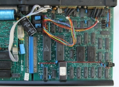
| While I was waiting for the drive to arrive, the
SDX itself was delivered. Up to this point, I did
not know which PROM would be in the controller, the
SDX controller can either be used to just give the MTX a
disk based BASIC system, or with the addition of an
80 Column video board to the MTX, allows the
computer to run CP/M 2.2.
On taking the cover off, I found that the
installed PROM was the CP/M version., that saved me
from having to replace it. |
 |
| I had managed to pick up an MTX with an
80
Column board installed from ebay a couple of months
earlier. Up to this point, I had not been able to
test the 80 Column board as it requires the CP/M
PROM to write to it. When I got it, the 80 Column
board had a very odd "end-user"
modification on the video output, but I removed
it and reinstated the original video output
configuration. |
 |
| Although I had not modified the disk drive PSU
to provide 5VDC to the SDX, I thought that I would
try the controller plugged into the MTX with the 80
Column board installed and see what happened. Major
good news! - both the 80 Column board and the SDX
appear to be working, I just need to work on the
drive now. |
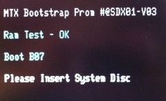 |
| I cobbled together a Sony MPF920 that I had been
using with my FDX, an ATX
PSU, as well as my SDX controller and tried to boot the
system using a Type "07" FDX System Disk.
The system accessed the drive, but the disk could
not be read.
I did not have any documentation to confirm the
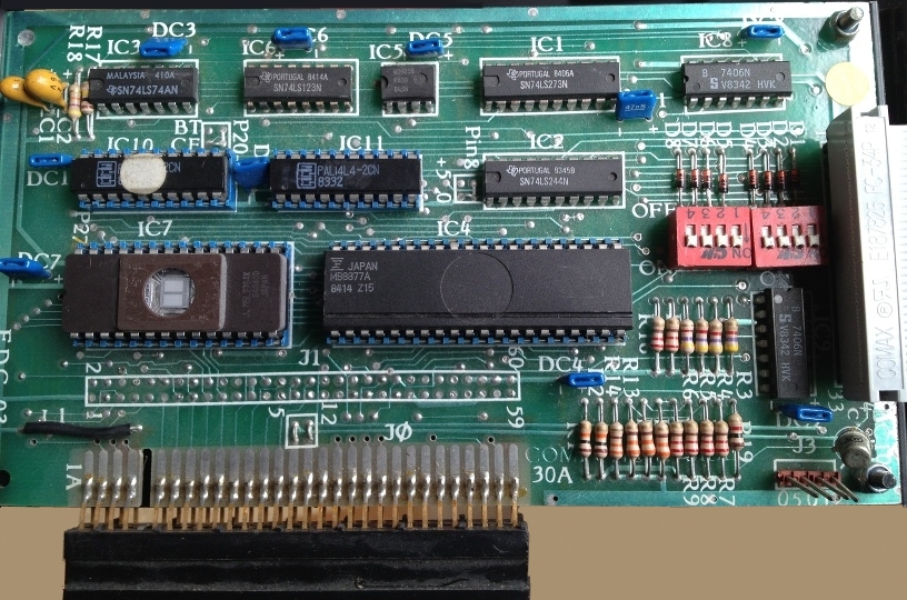
required DIP switch settings on the controller, but
Andy's site had a photo of Jim Wills'
SDX controller's (FDC03) DIP switches. |
 |
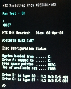
| The position of the switches on Jim's board were
the exact opposite of mine, so I tried resetting the
ones on my (FDC05) controller board to be the same,
i.e., all switches ON. As you can see, the SDX
could now boot successfully (from
drive "C", as the 3.5" floppy drive did not have a
link selectable address). I know how to fix this, but in the short term, this was
enough to demonstrate that my new "jerry-built" SDX
System works as it should!
I still have some minor changes to make,
including permanently changing the Sony drive ID,
fitting it into the enclosure and deciding whether
modifying the PSU is actually worth it.
In the meantime though, I now have a functional
SDX system! |
 |
|
After I created this page, I had some contact with
Tony Brewer, the designer of the SDX disk
controller. With Tony's help, I have created a
circuit diagram
for the FDC05 controller, the diagram also
details the functionality of the DIP switches.
|
|
Changing the ID of a Sony
MPF920 3.5" Drive |
| |
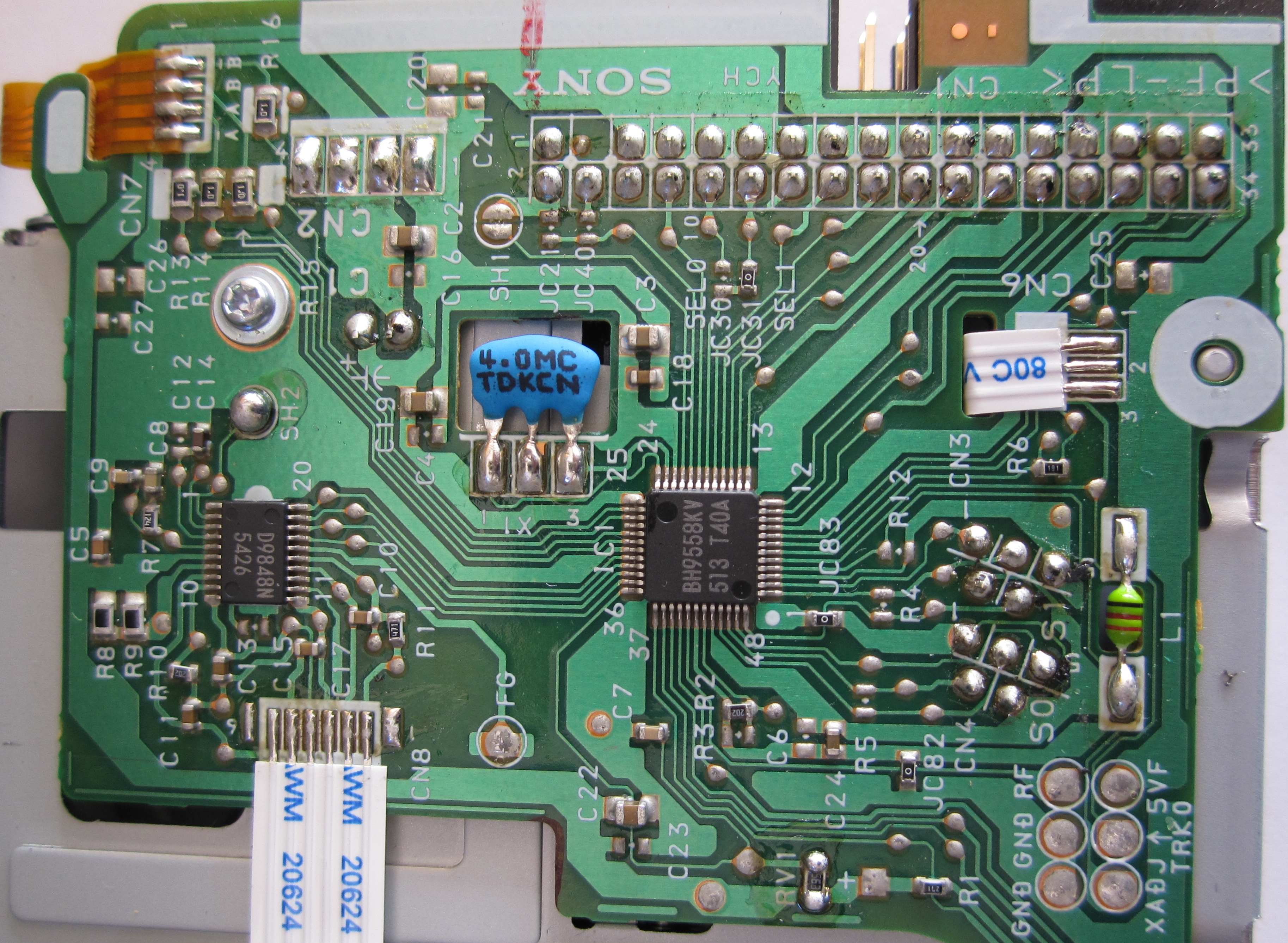
| Like most newer 3.5" floppy drives, the Sony
MPF920 does not have a jumper selectable drive ID,
however, it is relatively easy to make the change.
The drive is encased in a light steel shell which is
removed by "popping" 4 clips on the sides of the
drive to remove the top half and 3 tiny screws on
the base to remove the bottom half.
Once the case has been removed, the PCB on the
bottom of the drive can be accessed. |
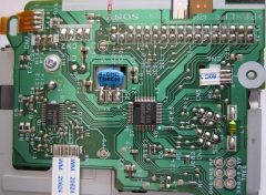 |
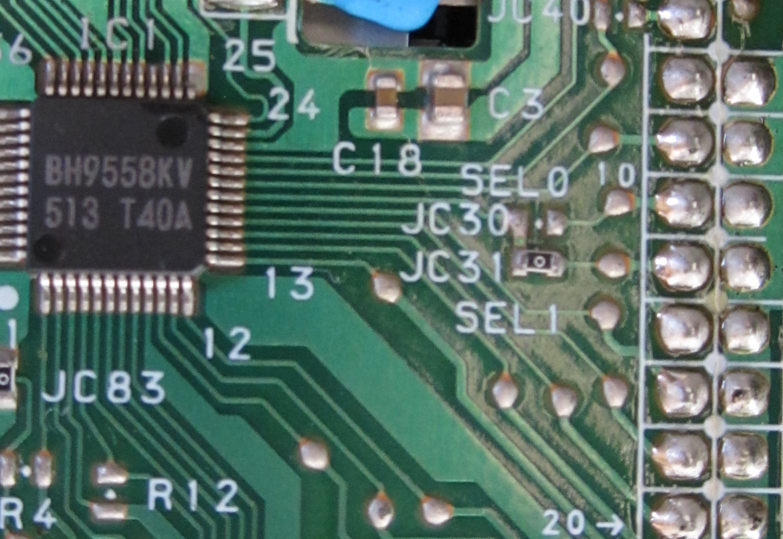
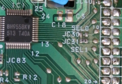
| Located between the square BH9558KV ASIC and the
data connector, you will see "SEL0" and "SEL1"
labels on the PCB. These identify the locations
where a
0 Ohm resistor is used to set the drive ID -
which is in the "SEL 1" position by default.
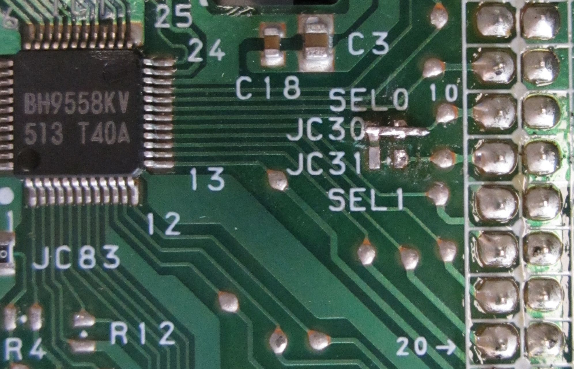
Remove the resistor from the "SEL 1" position (JC31)
and either move it to the "SEL 0" position (JC30),
or, it is probably easier to just solder a small wire
link between the "SEL 0" solder pads. |
 |
| Whilst the concept is "relatively easy", in
practice, you need a micro point soldering iron,
good eyesight and a steady hand. I think that I
probably have 1 out of 3!
- The 0 Ohm resistor is about 3mm long and half
as wide, I didn't even try to re-solder it across
the JC30 pads, instead, I tinned 3 strands of 0.2mm
wire, soldered it over the pads and snipped the end
off. The result is not beautiful, but it does the
job. |
 |
| |
|
| |
|
| |
|
|