|
"MTX Plus+" Power Supply
Production Version
The prototype MTXPlus+ backplane had
connections for external power using two VCC planes and two ground
planes. The VCC planes were reserved for +5VDC and +3.3VDC (for
future use) and backplane pin 17C was reserved for +12VDC.
Version 1 of the power board was designed to allow an ATX power supply to feed power to the
backplane.
Version 2 of the power board
was designed to allow "wall wart" power adapters to feed power
to the backplane, after suitable conditioning on the power
board.
When I started building and testing the prototype boards for the
system, I was fortunate enough to pick up a cheap Eurocard
backplane that I used for testing, but I knew that anyone else
that might be interested in assembling their own MTXPlus+
may not be so lucky.
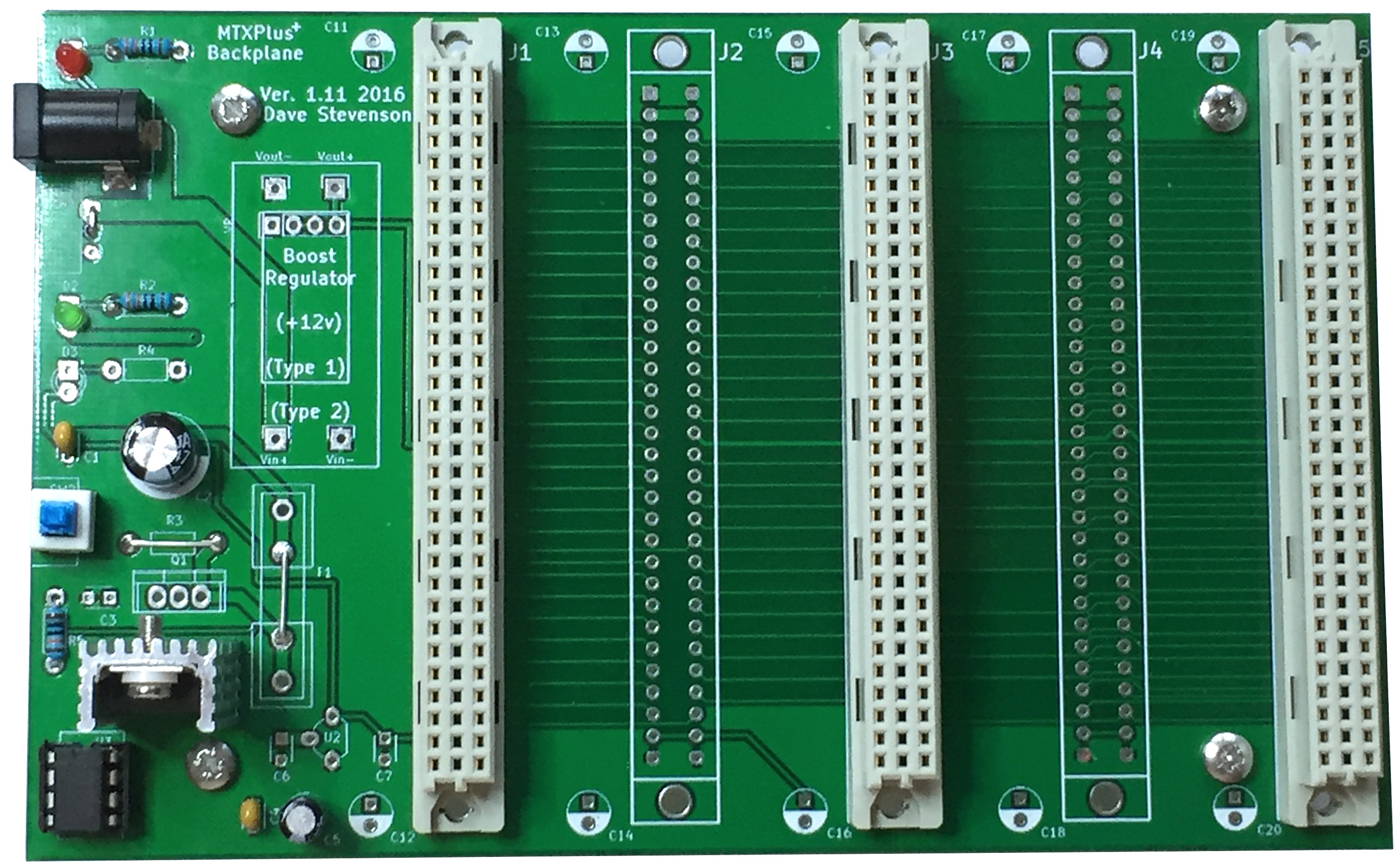
When I got to the point of designing PCBs for MTXPlus+,
I wanted to start with a backplane that others could use to
build the system. Although I wanted to keep the footprint small
to keep the manufacturing costs down, I realised that I could
put the power conditioning components on the backplane PCB and
do away with a separate power board and the first production PCB
was therefore a combined backplane and power board.
I was able to further simplify the design by dispensing with the
12VDC supply and regulation circuit. MTXPlus+ only
uses 12VDC for some optional features, including automatic SCART
aspect ratio switching, and perhaps a disk drive motor if a
physical disk drive were ever to be connected. Rather than
adding components to provide a regulated 12VDC supply from
another "wall wart", I have designed the board to accommodate a
cheap step up voltage module that will generate +12VDC from a
lower input voltage. You can see the small PCB installed close
to the power input connector. These modules are available for
under £1 on eBay.
At Martin's suggestions, the backplane now also incorporates the
MAX705 supervisory IC that controls system startup and reset.
The MAX705 will be removed from the CPU board when I get around
to making a CPU PCB, having reset on the backplane will save
having to build the same circuit on every CPU board that could
be used in the system.
Notes
MTXPLus+ Power Consumption
During the design phase, I "guesstimated" the power
requirements for MTXPlus+ based on the
datasheets for the major components, but once I had the
prototype boards made, I could empirically determine a
more accurate power consumption figure by removing the
supply fuse from the power board and measuring the
current in series with the load.
| Configuration |
Current drawn
(mA) |
| All bus slots empty |
17 mA (backplane LEDs) |
| I/O Board |
170 mA (CF connected) |
| Video Board |
505 mA |
| Z80 CPU Board |
235 mA |
| Z180 CPU Board |
165 mA |
| 6502 Co-Processor Board |
172 mA |
| Diagnostic Board |
128 mA (switched off) |
| Diagnostic Board |
200 mA (switched on) |
| |
|
| Typical
Configurations |
|
| Video & I/O Board |
635 mA |
| Video, I/O & Z80 CPU
Boards |
800 mA |
| Video, I/O, Diagnostic &
Z80 CPU Boards |
845 mA (Diag board off) |
| Video, I/O, Diagnostic &
Z80 CPU Boards |
1000 mA (Diag board on) |
The figures above indicate that an MTXPlus+,
configured with CPU, I/O and video boards would require
significantly less than 1A of power, even allowing for
some variation in component tolerances and some
fluctuations in the load.
Even allowing for some additional power for the serial
ports and other expansions, it should be possible to use
a high power 7805 regulator (e.g., an L78S05CV is rated
for 2A) on its own and
dispense with the TIP 2955. This can easily be done by
replacing the sense resistor with a wire link and
omitting the TIP 2955.
Temperature Considerations
The combined backplane and power board includes a linear voltage
regulator and a power transistor that are used to regulate the
raw DC voltage from the "wall wart" power adapter. These
components are cheap and provide good power regulation, the
downside is that they can generate a lot of heat. The efficiency
of a linear regulator depends on the difference between the
input and output voltages and how much current is being drawn by
your circuit. The greater the difference between input and
output voltage or the greater the current, the more heat will be
dissipated by the regulator. 1
The LM78xx series need a minimum of around 2.5VDC differential
between the supply and output voltages to provide stable
regulation and the voltage dropped over the regulator is
dissipated as heat, the greater the voltage difference, the
greater the heat produced. 9VDC and 12VDC power adapters are the
most common, but 7.5VDC adapters are also readily available and
is the suggested device to provide the power input to the PCB.
Even using a 7.5VDC supply, heat sinks will probably be needed
for the LM7805 and, if fitted, the TIP2955. With a 7.5VDC supply, these heat
sinks can be quite small, but if the user chooses to use a
larger voltage supply, larger heatsinks will almost certainly be
required.
The maximum operating junction temperature for a TIP2955 is
typically around 150 degrees C and for an LM7805, typically 125
degrees C. Although the devices will operate satisfactorily at
these temperatures, your fingers accidentally coming into
contact with them would get a nasty surprise! For personnel
protection, it is advisable to keep the surface temperature
below ~70 degrees C.
I knocked up a rough 'n' ready calculation in Excel to
calculate the size of heatsink required for a given current
consumption, there is a link to an on-line calculator at the
bottom of the page2, but you can find other calculators on the web if
you want to look. I plan to use the cheap plate type heatsinks
that rely on natural cooling (convection) but forced cooling (i.e.,
using a fan) would reduce the size of the heatsinks needed should you
want to use a higher voltage power adapter.
Heatsink thermal resistance is usually given in Degrees C/Watt
and gives a measure of the temperature rise that the heatsink
will undergo when cooled by natural convection for a given power
load that it is trying to dissipate.
References
1
sparkfun.com,
Power and
Thermal Dissipation
sparkfun.com,
Heat sinks and
thermal dissipation
electronics-cooling.com,
How to Select a Heat Sink
2
daycounter.com,
Heat Sink Temperature Calculator
designworldonline.com,
How to Select a Suitable Heat Sink
giangrandi.ch,
Calculating heat sinks
Texas Instruments,
Understanding Thermal Dissipation and Design of a Heatsink
|