|
"MTX Plus+" Power Supply
Version 2
My MTXPlus+ backplane has
connections for external power using two VCC planes and two ground
planes. The VCC planes are reserved for +5VDC and +3.3VDC (for
future use) and backplane pin 17C is reserved for +12VDC.
Version 1 of the power board was designed to allow an ATX power supply to feed power to the
backplane.
I have now designed and built a second version of the power
board, although the ATX PSU should have been a good solution for
providing power to MTXPlus+, I have replaced it for a
number of reasons :
| While I was using my MicroATX PSU for testing
MTXPlus+, it was connected to the power
board using a couple of cheap ATX PSU extension
cables, as time went on, these cables became more &
more temperamental and started causing power drop
outs. |
| Even the "small" ATX PSU that I was using was
designed to supply well in excess of what MTXPlus+
will ever need. I was using the same model of PSU (a
HEC-200) that I had used in my
FDX PSU
replacement project, this PSU can supply 16A at
3.3V, 12A at 5V and 10A at 12Vs, even though small
by PC standards, it is overkill for MTXPlus+. While
fine for development and testing, the physical size
is also far greater than it needs to be for the
final design. |
| Using a dedicated design for the PSU will allow
the system to be assembled from components should
MTXPlus+ ever make it to the "product" stage. |
The power supply does not actually need to connect to the
backplane itself, but in my case, as there are plenty of spare
bus slots, it is a convenient location for the card. Although
plugged into the backplane, the only signals on the power module
actually connected to the bus are the bus voltage lines and
ground, this will allow the bus voltage status to be displayed
on the power module, but the power lines themselves will be
wired directly from the module to the backplane - not through
the bus interface connector. I decided to use dedicated
power wires when I had less clarity on what the MTXPlus+ power
requirements were likely to be. Now that the power requirements
and supply rating have been reduced, I may revisit this. The
+5VDC, +3.3VDC (future) and ground connections on the backplane
have 2 x DIN41612 connector pins allocated, each with a rating
of 2A, so I could potentially feed power to the backplane
through the backplane connector up to a maximum of 4A per rail.
The MTXPlus+ system bus was designed to support
+12VDC, +5VDC and +3.3VDC, the latter voltage was provided to
cater for future expansions that may have needed a 3.3V power
supply. With MTXPlus+ essentially complete and no
requirement for 3.3V power having come to light, the version 2
power board will only provide 12V and 5V. Should it be necessary
to provide 3.3V at a later date, space has been left on the
power board for the components to generate 3.3V from the 5V
supply.
The input power to the board will now be supplied by low voltage
DC "wall warts", providing the power feeds for the +12V and +5V
rails, and suitable regulation to ensure stable voltage levels.
Wall wart
AC adapters are easy to find on eBay, but come in different
flavours, from cheap, unstabilised adapters, providing pretty
ropey DC voltages somewhere in the region of what they say on
the case, to more expensive, regulated supplies that could
provide a clean and stable supply for MTXPlus+.
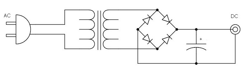
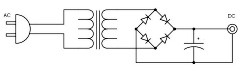
| A cheap unregulated wall wart will probably just
contain a step down transformer, regulating diodes and
an electrolytic capacitor across the output to provide
some smoothing. |
 |
More expensive wall warts may include a
switching regulator circuit to provide a stable output, but
without testing them in advance it is not guaranteed that an
off-the-shelf (or off eBay) supply would be suitable for
providing power to MTXPlus+, or indeed, anything else
! For that reason, I decided to design the Version 2 board based
on the assumption that the input power would not be clean and
would require to be stabilised on the power board.
Home computers from the 1980s typically used power supplies
based on the use of
linear
voltage regulators, such as the
LM7805s that
Lez had supplied us with in his
kits of parts. As I had them available, power regulation on
the Version 2 PCB was based on the use LM7805 and 7812
regulators. To maintain a stable
output voltage, the LM78xx needs to have a minimum overhead of
about 2.5V above the required output voltage. However, this
excess input voltage is dissipated as heat, the bigger the
overhead, the hotter the regulator will get, so, ideally, the
input voltage should be little more than the minimum to provide
stable regulation.
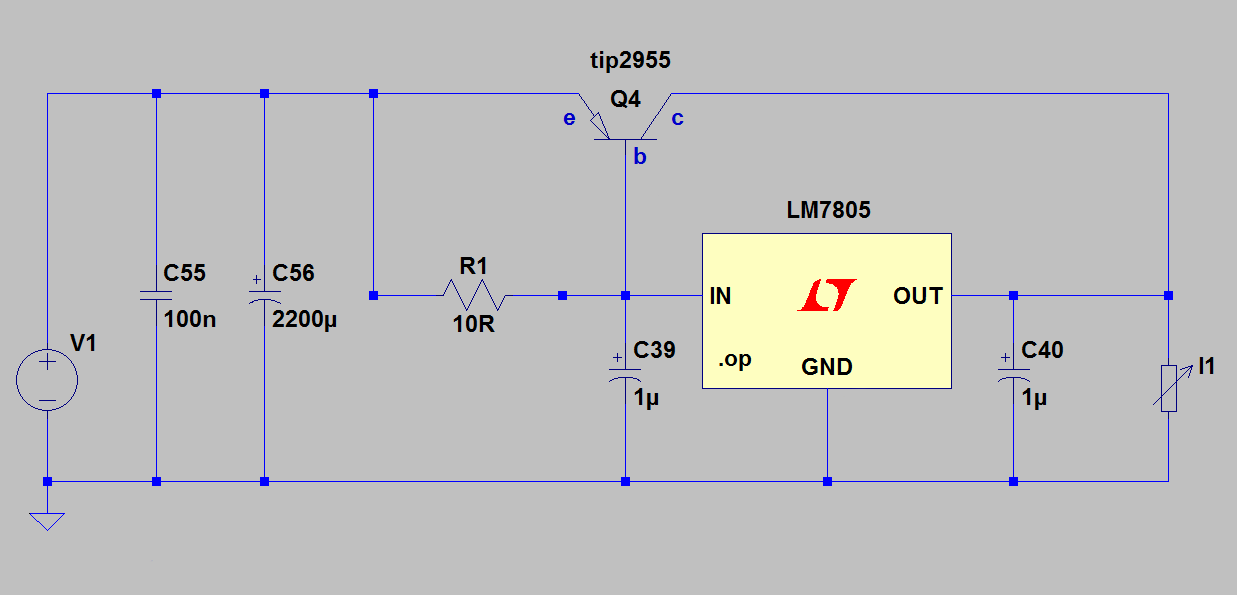
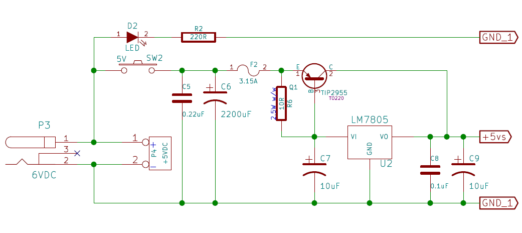
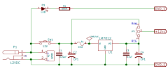
+5 VDC Supply
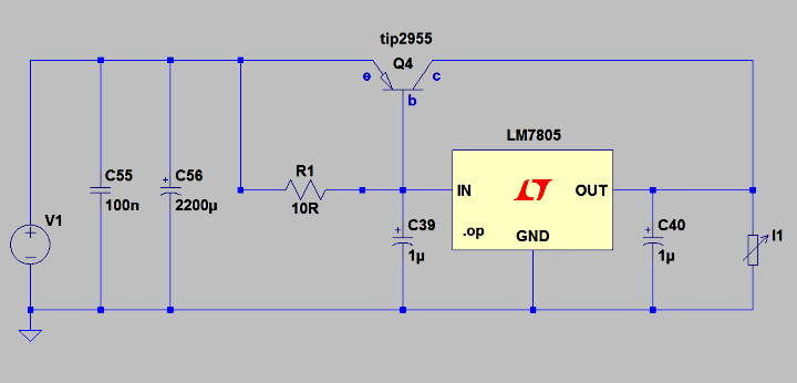
The schematic above shows the circuit for the stabilised +5V
supply for MTXPlus+, if you are familiar with the Memotech MTX,
you may find that it looks somewhat familiar! The circuit uses a
LM7805 linear regulator for voltage regulation, but R1, with a
value of 10 ohms, ensures that the majority of the current is
switched through the TIP2955 power transistor and only a minimum
supplied by the LM7805.
Depending on the manufacturer and model number, an LM7805 can
normally supply approximately 1.0-1.5 amps, the MTX computer
board has a 3.15A fuse in the +5VDC supply line, suggesting that
the MTX power requirement was somewhere close to this, perhaps
2-3A, well in excess of the capacity of an LM7805. The use of a
TIP2955 to provide current in excess of the capacity of an
LM7805 seems to be a pretty common arrangement, so while the
lower power requirement for MTXPlus+ may have meant that an
LM7085 on its own may have been sufficient, I wanted to make
sure that I was not going to be power limited.
Although I had a pretty good idea of how the TIP2955/LM7805
combination worked together and how the sense resistor R1 was
used to set the bias between the TIP2955 and LM7805, I wanted to
model the circuit to evaluate the effect of changing the value
of R1 on the current split between the two.
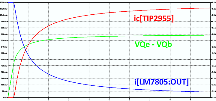
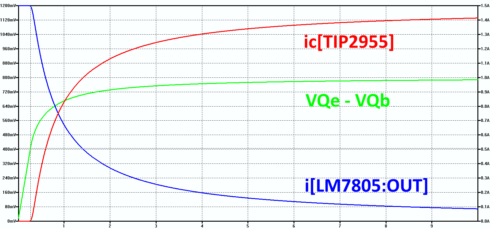
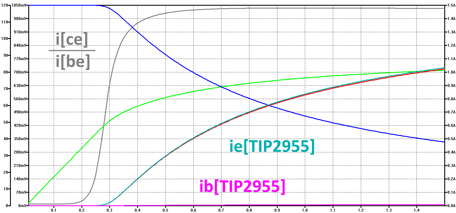
The trend shows how the current
through the TIP2955
and LM7805 varies as the value of the sense resistor, R1, is
varied from ~0 Ohms to 10 Ohms and the corresponding voltage
differential between the Emitter and Base of the transistor
for a fixed load of 1.5A. When the sense resistor value is 0,
the transmitter's base and emitter are at the same voltage,
the transistor is switched off and all of the load is
supplied by the LM7805. As the value of the sense resistor
increases, a voltage differential is created between the
transmitter's base and emitter.
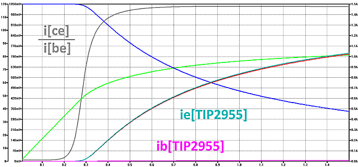
The system behavior can be seen more clearly by zooming in
on the range 0 to 1.5 ohms; when the sense resistor value is
zero, the transistor's emitter and base are at the same
potential and there is no appreciable current flow at the
emitter/base
or emitter/collector
junctions. The transistor is essentially inactive in this "cut-off"
region.
As the value of the sense resistor starts to increase, a
voltage difference between the emitter and base develops and
increases with the resistance.
Zooming in on the range below 1 Ohm shows that the currents
begin to change when the value of the sense resistor starts
to increase above ~0.27R and the corresponding voltage
difference between the transistor's base and emitter
(VQe
- VQb) increases above ~410mV when the
transistor urns on and starts to pass current from the
collector.
The above trends show that a 1 Ohm sense resistor would
limit the current from the LM7805 to around 0.7v, a 10 Ohm
resistor would limit the LM7085 current to around 0.1A and a
3 Ohm resistor would set the LM7805 current to around 0.25A.
In all cases, the TIP 2955 would pick up the rest if the
load. A typical TIP 2955 has a maximum collector current
rating of 15A - much more than MTXPlus+ requires
and a level that would risk damaging other components and
PCB traces under fault conditions, therefore, a fuse should
be installed in the TIP supply line as Memotech did in the
original MTX512
power circuit.
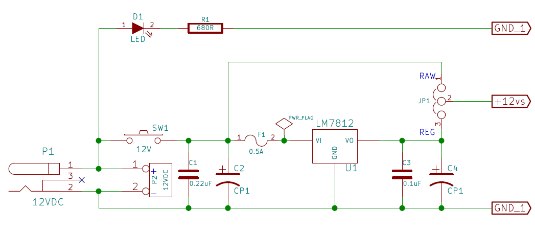
+12 VDC Supply
The +12VDC supply is only used for aspect ratio switching of
the SCART connection, power for the RS232 serial ports and
potentially, for a disk drive motor should a disk drive
eventually be attached to the system. These power
requriements are well within the capacity of an LM7812.
+3.3 VDC Supply
The 3.3VDC rail is included on the MTXPlus+
backplane to allow the flexibility to add modern 3.3V
devices should it be necessary. The Version 2 power supply
board will not supply +3.3VDC by default, but will have
sufficient free space to allow a 3.3VDC regulator to be
powered from the +5VDC supplty.
|
Backplane Power Supply |
Schematic diagram of the
+5VDC portion of the Version 2 board
Download
the complete diagram as a PDF |
 |
Schematic diagram of the
+12VDC portion of the Version 2 board
Since
the quality of +12V power rail is less critical than
the +5V line, the +12V line includes an option to
bypass (or not install) the regulatory components
and power the rail from a good quality external
supply. |
 |
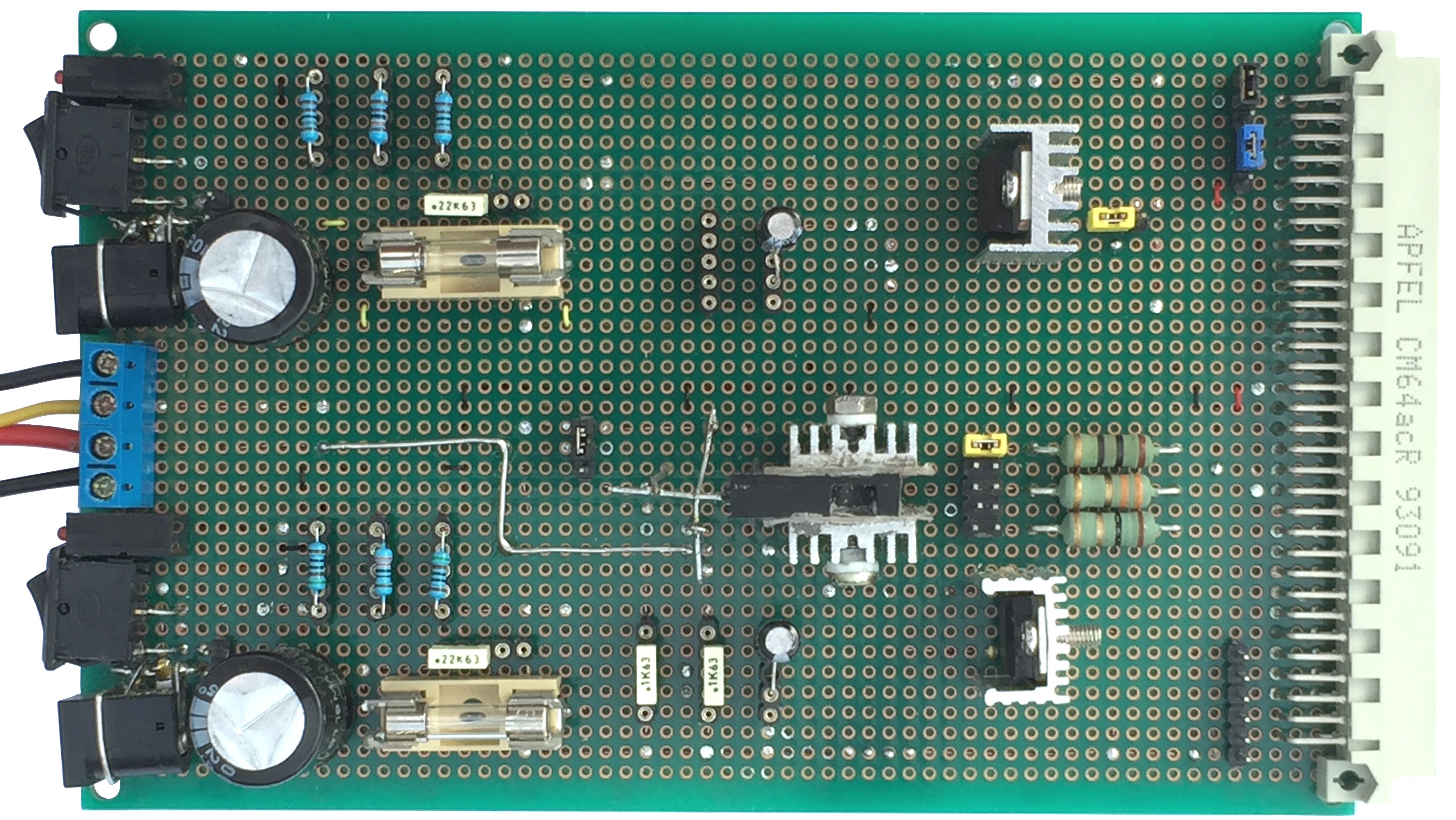
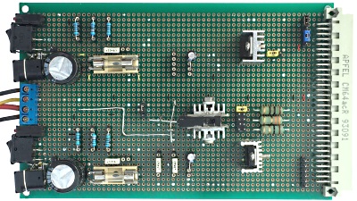
Component side of the Version
2 power board.
The +12VDC portion is on the
top half of the board and the +5VDC portion on the
lower half. |
 |
|
The
solder side of the board :-
|
coming soon . . . |
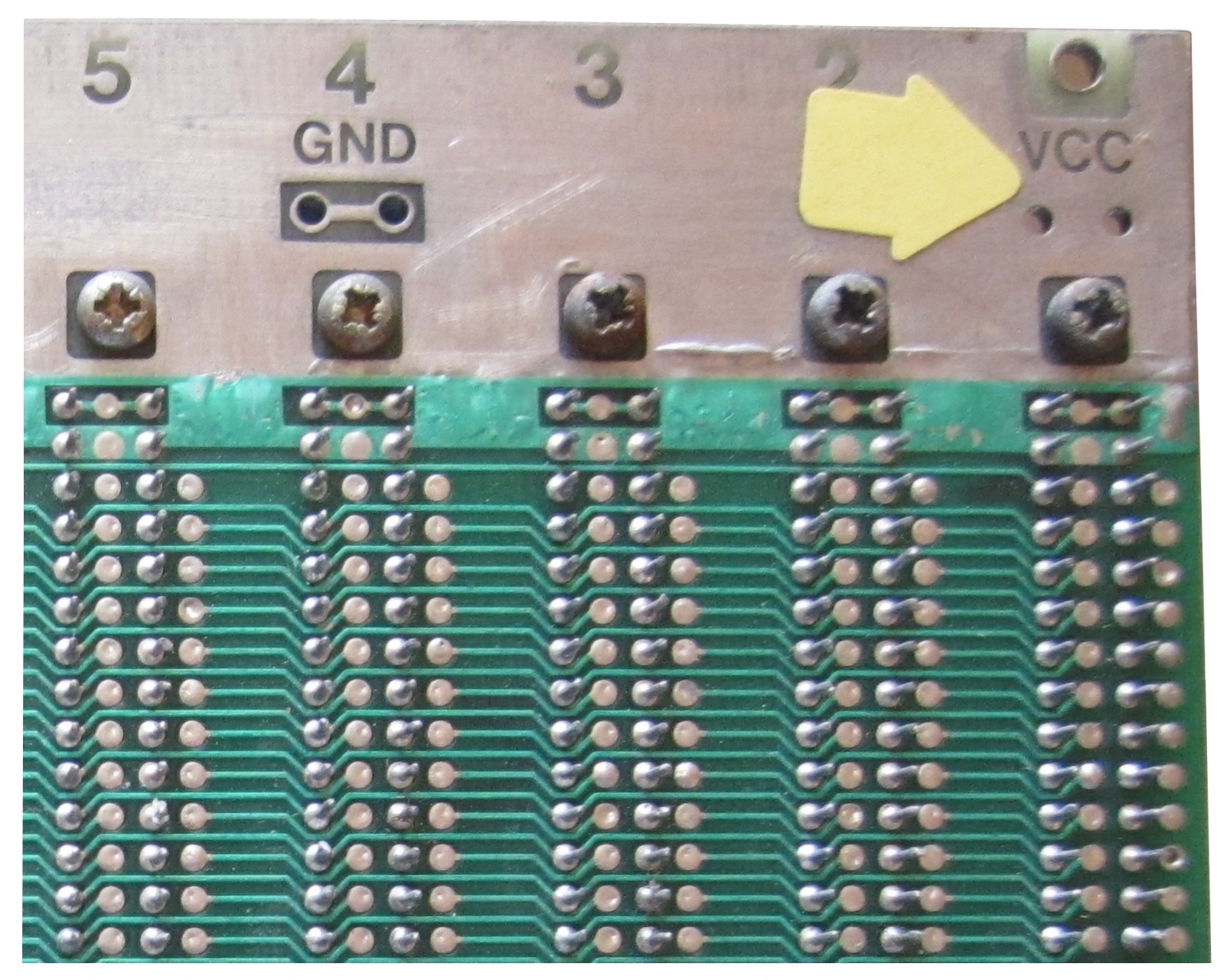
|
A close up on the rear of the backplane showing a
pair of the power and ground plane connection
points, there are four of these pairs on each of the
planes. On this one, the +5V supply will be
connected to a couple of these points. Similarly,
ground connections will be made on the other side of
the board - you can see the insulating space between
this power plane and the ground connection on the
other side. +3.3V and ground will be connected to
the bottom plane in the same way, and the +12V line
will connect directly to the backplane on pin 17c on
any slots where it is required. |
 |
Credits
-
The voltage simulations on this page were produced
with
LTSpice IV, "a high performance
SPICE simulator,
schematic capture and waveform viewer with enhancements and
models for easing the simulation of switching regulators."
LTSpice
IV is available free from Linear Technology

References :
Sparkfun,
Unregulated
Power Supply Tutorial
DXing.info,
A
Dummies’ Guide to Working with Wall Warts
Instructables.com,
Hobby Electronics Power Supplies Part 1: Wall Warts
|