|
 |
The Memotech MTX Series |
 |
MTX Co-Processor
Courtesy of Martin Allcorn
Martin has developed a co-processor interface for the MTX,
inspired by the "Tube"
interface of the
BBC Micro,
he's calling it MTXPipeTM.
The tube was a fast bus interface that provided connectivity to
additional co-processors, including a faster 6502, a Z80
or an ARM processor, the BBC Micro continued to handle I/O
processing whilst the additional co-processor could execute the
Language Application.
Acorn co-processors used a custom
ULA in
the co-processor expansion "wedge" that handled the
inter-processor communication, the processors were not
synchronised, the ULA included buffers used to store data until
the other processor was ready to read it.
|
Design & Build |
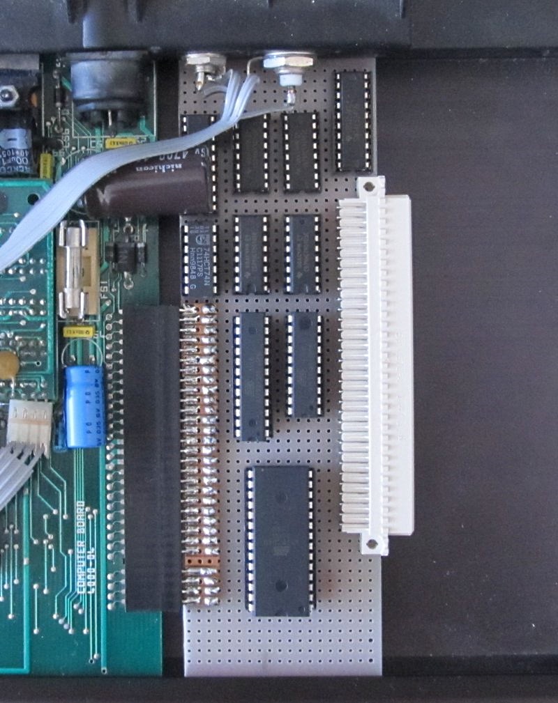
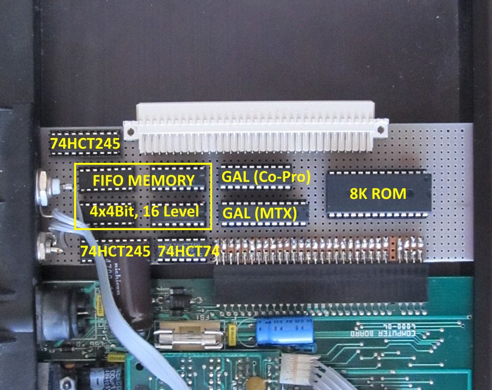
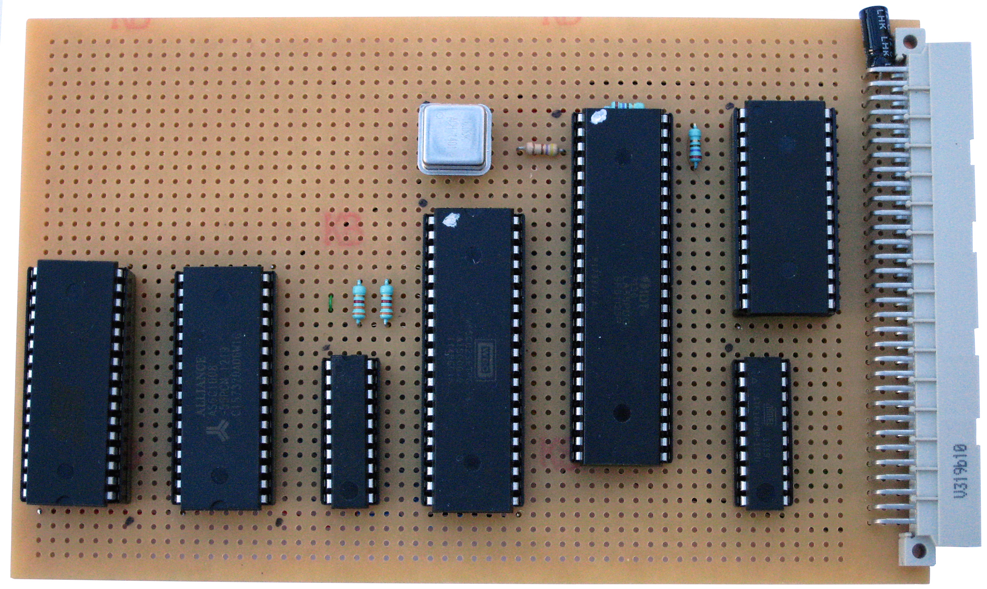
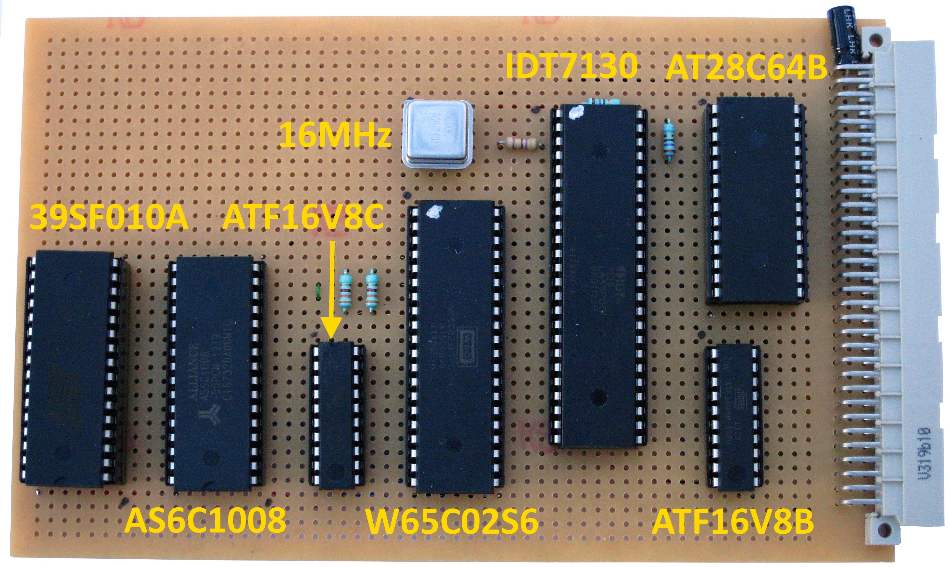
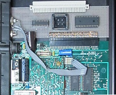
Martin's mock up of his initial co-processor interface
design.
The 74HCT245 transceivers make up the
status port for each CPU to read the
FIFO status, 245s were chosen for their tri-state
outputs.
The 4, 16 pin chips are 4 bit wide, 16
level FIFO memories, they're paired up to make the 8 bit
wide send/receive pipes between the CPU's.
The
74HCT74 dual flip flop is an interrupt controller, one
CPU operates the set function, the other drives the
reset.
The 24 pin GAL is on the MTX side,
the 20 pin on the co-pro side, they do all the timing
signals for the FIFOs. The MTX side does a full I/O
decode which is why it needs the extra pins. The Co-pro
side will need logic on the CPU board to make the
signals more Z80 like, so the interface only needs to do
a partial decode. |
 |
 |
The proposed
design MTXpipe uses 4
addresses/ports to :
| Read/write the FIFOs |
| Read the status register |
| Set the interrupt flip-flop
|
| Reset the send FIFO |
| Reset the write
FIFO |
| Clear the interrupt flip-flop |
| Reset both
FIFOs |
| |
Using reads or writes to perform the reset/interrupt actions instead of
using bits in a register saves board space.
Both sides would get the same 4 port access, at this
point, the intention was that the MTX side would be
passive, and responds to requests from the Co-pro, which
is effectively in charge.
The plan was that the
software should put the relevant transaction data in the
pipe then set the interrupt. 16 bytes is ample for
screen/keyboard processing. Genpat is the longest VDU
sequence at 12 bytes. |
Martin then
developed a simplified design using a 1 kB Dual Port
RAM, the interrupt flip flops and data registers are no
longer required and the paging logic is much simpler,
being memory mapped instead of I/O mapped.
Each
“side” gets its own read/write/chip select pins and a
BUSY signal is wired to the
CPU’s WAIT pin to stop
simultaneous access to the same location. One location
on each side sends an interrupt to the other side,
reading the location from the other side resets the
interrupt. |
 |
The initial
test passes with flying colours, the ROM pages in and
out as required.
The next test will be to plug in
the 1kB dual port RAM and write some code to test it on
the Z80 side. |
 |
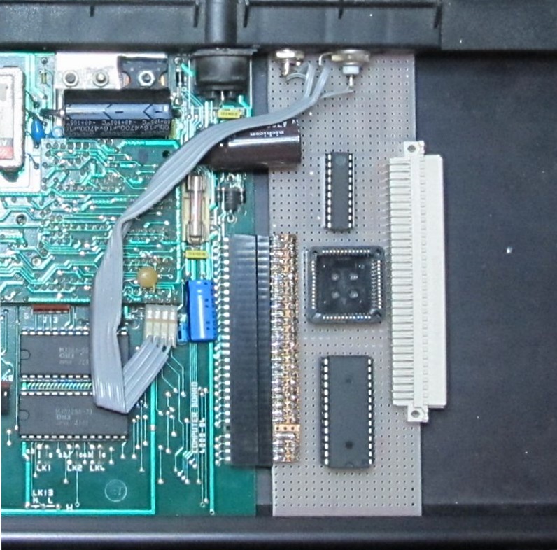
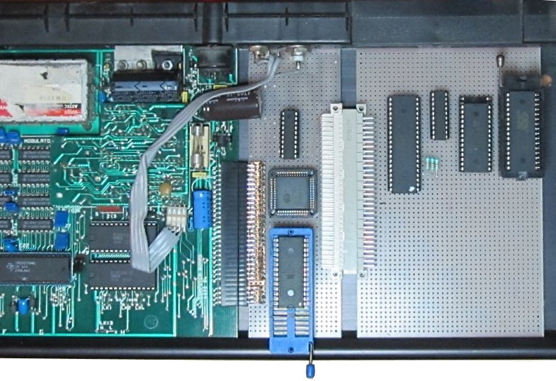
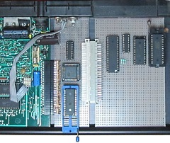
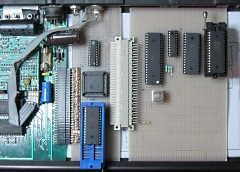
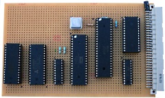
The
MTXPipe board connected to a very basic
6502 Co-processor board, temporarily using ZIF sockets
for ease of replacement during testing.
The
co-processor board has 32kB RAM, 32kB of ROM, it is
clocked of the MTX 4MHz clock signal but will ultimately
have its own, faster, CPU clock. |
 |
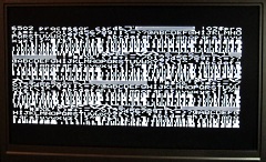
| The simple
test ROM on the 6502 side writes a test pattern into the
shared RAM, and the Z80 side is able to read it back.
|
 |
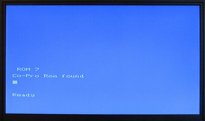
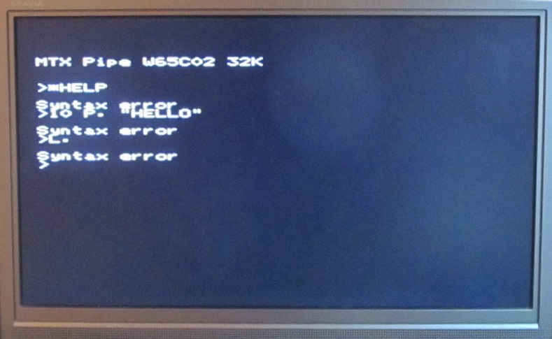
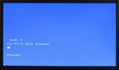
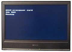
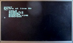
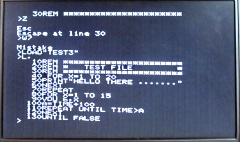
| The system
booting from a simple ROM on the Co-processor board, as
the screen shows, there is a small issue with the
displayed text - an extra character in the "Ready" text,
possibly related to a timing issue that required further
investigation. |
 |
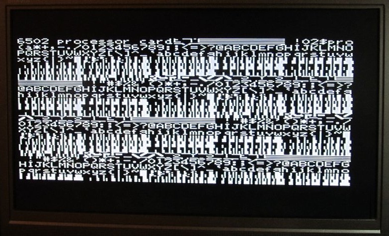
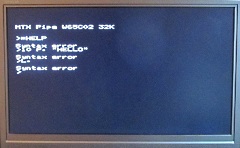
Some
progress, text can be typed on the MTX keyboard and
passed over to the 6502 processor, although it is being
misinterpreted on the 6502 side - even though it is
displayed correctly.
The initial goal is to get
BBC BASIC to run on the system, so far,
Operating System calls OSWRCH,
OSRDCH and minimal OSWORD and OSBYTE are supported. |
 |
Design
development . . . .
The Co-processor now has it's
own clock, the 12MHz oscillator is directly driving the
CPU without the need for any supporting components.
The additional resistor adjacent to the connector is
required to prevent the CPU from affecting the interrupt
line during a WAit-for-Interrupt
(WAI) instruction which was added in the
WDC W65C02 processor. |
 |
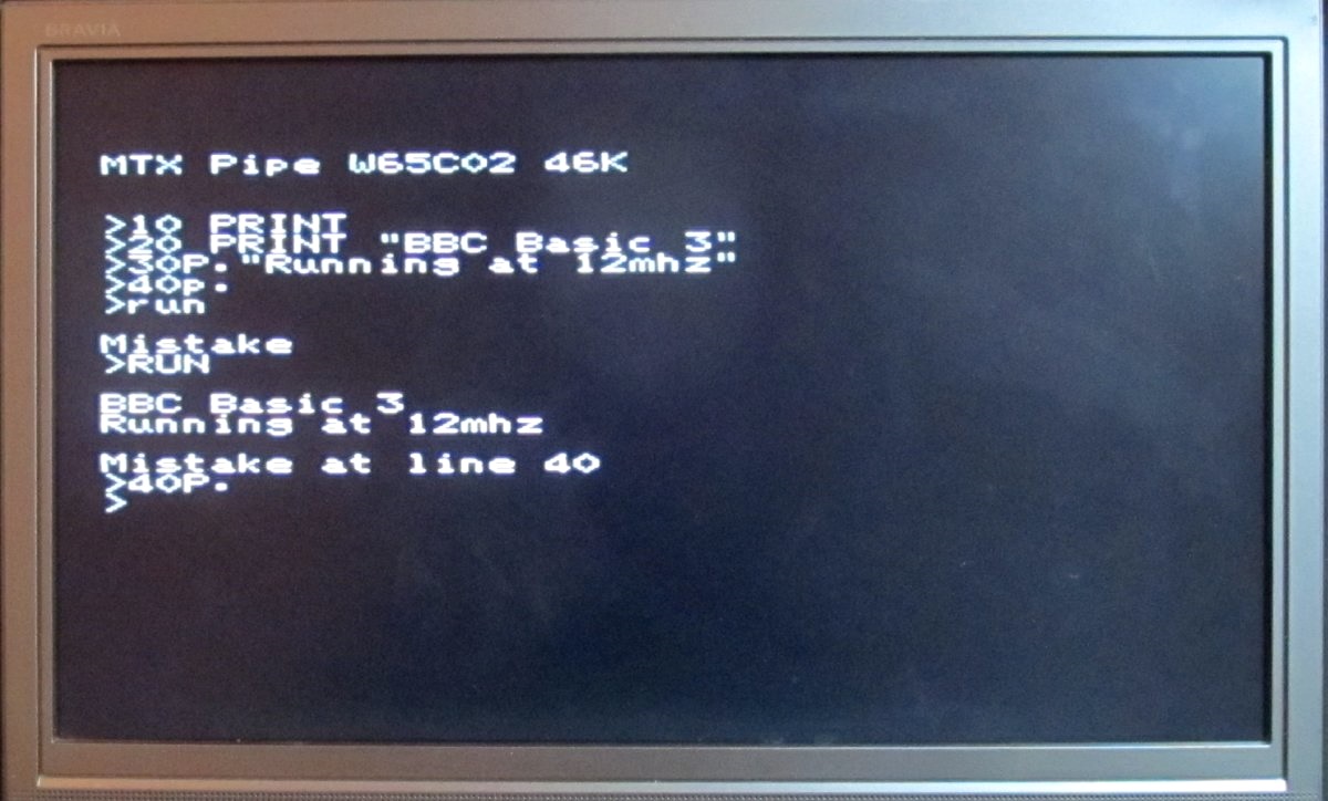
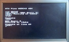
The system
now reporting 46K of RAM and running BBC BASIC 3.
PCW benchmark 8 (which
performed maths operations) speeds :
49.9 seconds for the BBC Model B (2 MHz 6502)
44.9 seconds for the MTX 512 (4MHz Z80)
8.2 seconds for the Co-processor (12 MHz 6502) |
 |
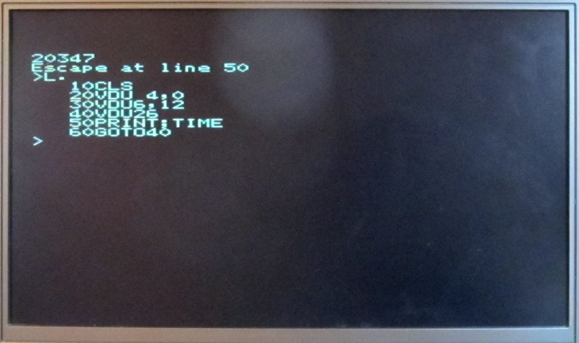
Now with
limited support for VDU codes that are compatible with
the MTX’s display system, so VDU 26
is “home” and not VDU 30 which the BBC uses.
Likewise COLOUR in basic will
do weird things, but VDU 4,x
or VDU 6,x will set the
colours. |
 |
To compare
the speed of computers for their reviews in the 80s,
Personal Computer World used a series of eight
BASIC benchmark programs.
Results for the Co-pro
are shown in the table, they have a mean of 1.87s,
compared to the BBC Micros 14.3s and the MTX500 of 19.3s |
|
BM1 |
0.09s |
|
BM2 |
0.38s |
|
BM3 |
1.06s |
|
BM4 |
1.11s |
|
BM5 |
1.17s |
|
BM6 |
1.79s |
|
BM7 |
2.77s |
|
BM8 |
6.61s |
|
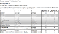
(Click to see benchmark details) |
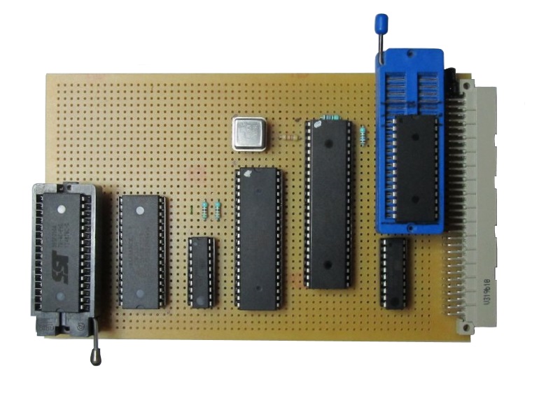
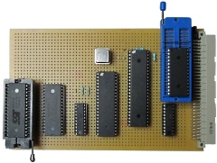
The co-processor board with a form factor suitable for
connection to the
MTXPlus+ system bus. The Z80 is clocked on the
MTXPlus+ side at 10MHz and the 6502 is clocked at 16MHz
by the on board oscillator.
The large (48-pin) DIP
chip is the dual-port RAM, rather than the PLCC used in
the MTX format board. Footprint is not an issue here and
the DIP was easier to wire than a PLCC socket. |
 |
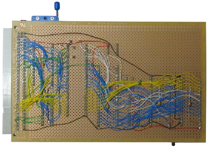
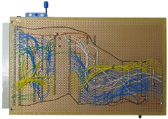
Wiring side of the MTXPlus+ board, the wiring for the
dual port RAM clearly shows the segregation between the
MTX side and the 6502 side.
The only signal to cross
domains is RESET, the 6502 system is totally self
contained. |
 |
|
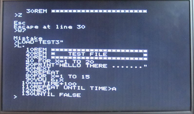
The MTXPlus+ co-pro running BBC BASIC and loading a
program from the MTXPlus+ Compact Flash drive |
 |
December 2015
I received a
surprise early Christmas present from Martin !
Wow ! - One fully built 6502 Co-Processor board for
MTXPlus+ |
 |
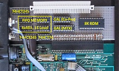
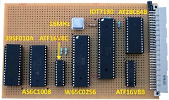
Annotated to show the major components on the board.
The largest chip is the 1k x 8, dual port Static
RAM, an
IDT 7130 |
 |
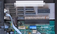
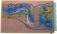
A higher res. photo of the wire side of "my" new
co-processor board.
As usual, I am really
impressed by the quality of Martin's construction - my
boards never look that neat ! |
 |
|
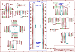
MTX Version Schematic |
Schematic of the current version of the MTX Co-processor
board.
Although the schematic shows a 128kb EEROM
and a 128 kb RAM on the 6502 side, other devices are
supported, including flash memory and other sizes of
RAM. |
 |
|
|
|
|
|
|
| |
|
The Techie Bit
With the design pretty much complete, it's time to say a few
more words about how it works. Martin has written a few words of
explanation in
his post on Memorum.
Currently, there are two different versions of the co-pro board,
one for the original MTX and one for
MTXPlus+. The MTX version
is built in 2 parts, an Interface board
and the processor board.
It's done that way for 2 reasons:
-
It leaves more room on the processor
board for components - this was not an issue with the test
board, but it could be for other processors like the
68008
or
9900 that Lez generously donated. These are physical
larger and in the 9900's case, have a 16 bit data bus.
-
Cost. The 1K dual port ram used for
communications actually cost [Martin] more than the 6502 did
Interface Board
The slim interface board consists of an 8k ROM, the dual port
RAM and a 15ns
GAL.
The GAL pages the ROM into slot 7 and is used to save space,
timing on the MTX side is fairly relaxed and so I could have
used standard logic chips. The GAL also pages the top 256 bytes
of the 1k RAM into the top of the ROM bank. [Martin] used the
Cypress
CY7C-131 on this board, and the
IDT7130 on the MTXPlus+
version of the board as they both work the same way.
The top part on the RAM is required, as the top 2 locations of
ram also act as interrupt controllers, one for each side. 256
bytes are used as this enables the transfer of a full CPM sector
and control information, with the minimal loss of available ROM
space.
6502 Processor Board
The 6502 processor board has a W65C02-14, 128k static RAM, 128k
flash, a 7ns GAL and an oscillator to allow the 6502 to be
clocked independently from the Z80.
For a language, the 6502 is currently using HiBasic
3 from the BBC Micro's external 6502 processor,
that's a 16k image, and is designed to allow 2k space for the
Tube OS, I've used that space, and allocated another 2k below
the language rom, making 20k in total. That leaves room for 44k
of system ram. The GAL pages the RAM chip in for the lower 44k
of the memory map, and the ROM in for most of the upper 20k. The
256 bytes of the dual port RAM is fitted into a "page" near the
top of the 2k tube ROM area. The un-used areas of the Flash and
RAM aren't accessible
The 6502 is currently clocked at 14.3Mhz (16MHz on the MTXPlus+
version), which is why the board needs the fast GAL, standard
logic would have restricted the CPU to a much slower clock rate.
The 6502 is in charge of all communications across the dual port
RAM. The replacement for the tube ROM has a VERY restricted
subset of the BBC MOS running, but it is enough to print, read
the keyboard, and save/load basic to the CFX that's plugged into
the external connector on the other end of the MTX..
The Z80 however controls the 6502 interrupts, and is currently
generating a 100hz interrupt as used by the BBC. The 6502 to Z80
interrupt isn't connected. The Z80 control software works by
constantly reading the shared ram for new instructions from the
6502.
References :
Support Group Application Note AN004, Acorn
Computers, 1992
BBC BASIC On-line reference manual at
benryves.com
BeebWiki - 8-bit
Acorn Computer Wiki on mdfs.net
|