|
 |
The Memotech MTX Series |
 |
MTX PSU
Replacement

Background
The
Power Supply for
Memotech MTX computers is nothing more than a
multi-tapped transformer, all voltage regulation & smoothing
is done on the MTX computer board, for a complete
description of the MTX power supply and voltage regulation
circuits, see my MTX PSU
page.
Replacement Options
Compatible PSU (AC)
Since there are no "off-the-shelf" replacements
for the MTX PSU (transformer) available, until recently, a lost
or failed PSU would render an otherwise working MTX computer
inoperable. Mark Kinsey (1024MAK) has designed a modern
replacement for the MTX PSU, the design was first published on
the
Memotech Forum. With Mark's permission and with
contributions from David Kimberlin Wyer - who has assembled a
110VAC version, design and construction of the replacement PSU
is also described on my page here.
Mark's replacement PSU is the easiest way to
replace a failed MTX power supply, it is a direct replacement
and plugs into the MTX power connector without needing the MTX
to be modified in any way. For people who don't have the skills
to make changes to the MTX themselves or who want the
convenience of just buying a replacement PSU, then it is the
best option.
Alternative PSU (DC)
For anyone with some basic soldering skills, there is an
alternative option, albeit one that requires some modification
to the
MTX itself. This page shows one possible method of providing DC
only power to a Memotech MTX computer.
As described on my MTX PSU
page, the MTX computer board derives +12VDC, +5VDC, -5VDC
and -12VDC from the low voltage AC tappings on the PSU
(transformer). With some minor modifications, it is possible to
use a DC only power supply and feed the required DC voltages
directly to the MTX computer board. Memotech did exactly that
when they used a MTX computer board and a "Skynet"
SNP-3031 PSU, to build the
Reflex Controller in my Video Wall system.
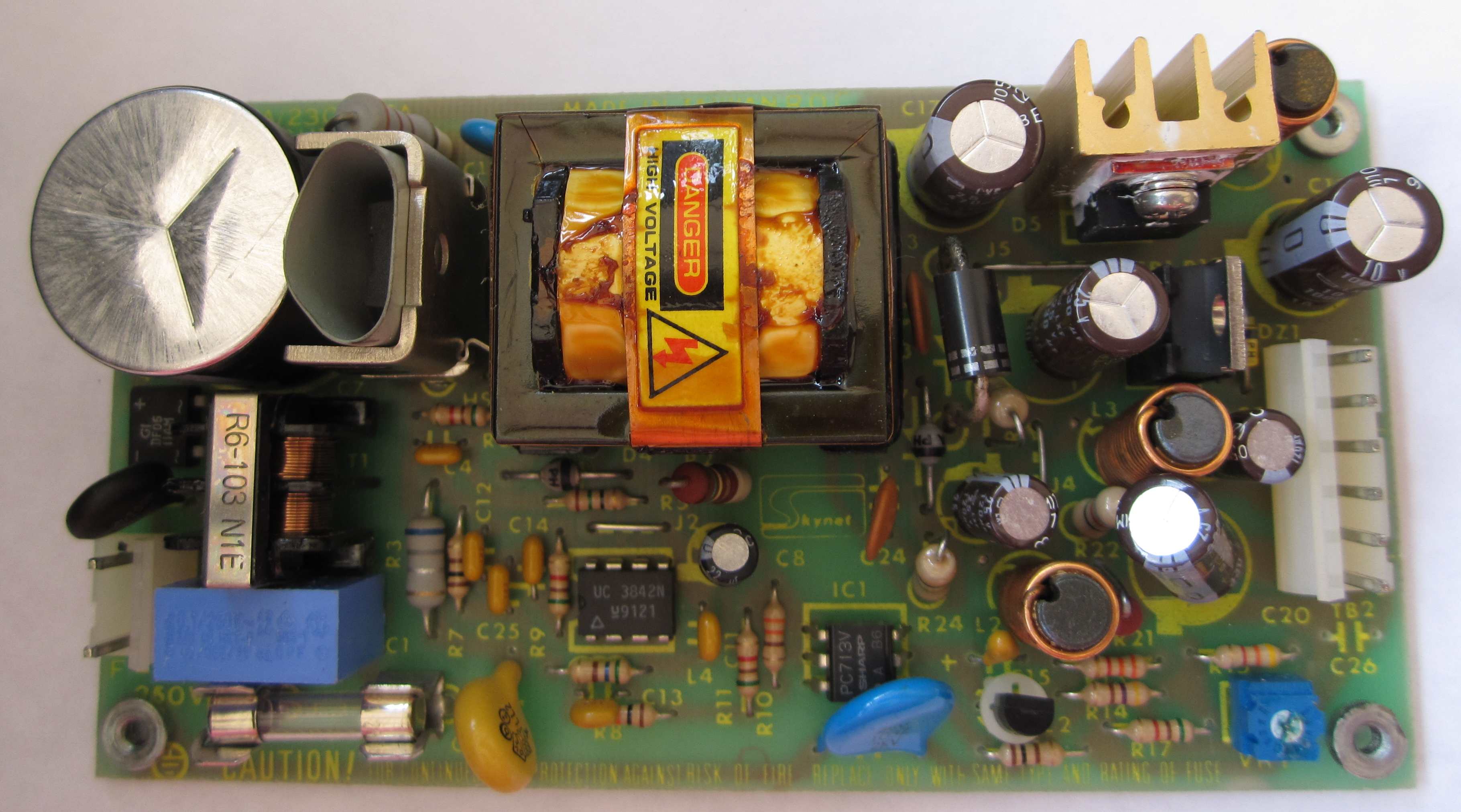
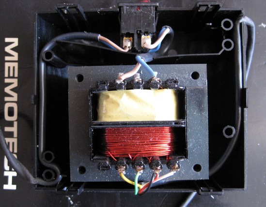
| The internals of my Reflex
controller, as you can see, all of the power components,
including the 5VDC fuse, have been removed. Power is
supplied to the board through the wires soldered
directly to the pads on the PCB intended for the DIN
socket, +12VDC (pink), +5VDC (red), 0V (black) and
-12VDC (blue). |
 |
Memotech used a PSU manufactured by "Skynet",
Model Number SNP-3031 :
Input specifications: 120V-1A, 240V-0.5A, 50/60Hz.
Output specifications; V1: +5V/2A, V2: +12V/1.5A, V3:
-5V/0.3A.
(An open frame PSU such as this would
not fit inside the MTX computer case and would not be
suitable for replacing the standard PSU) |
 |
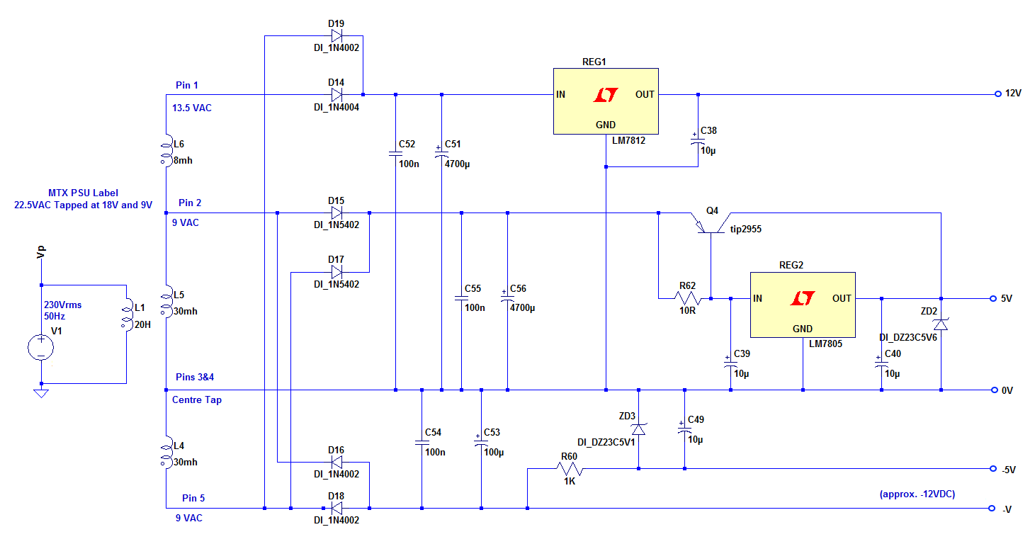
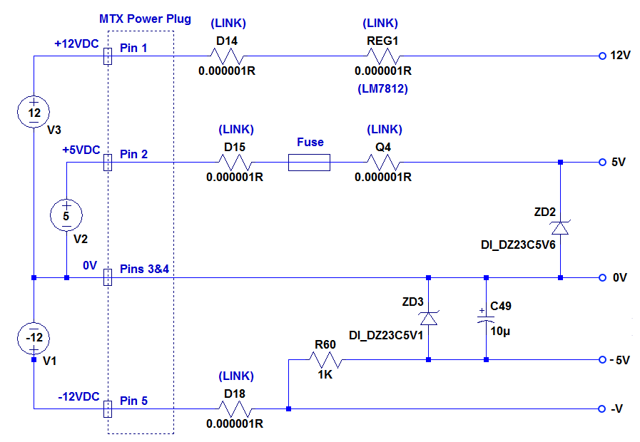
MTX Power Regulation
An
LTspice representation of the MTX power regulation schematic is shown below
: :
| Voltage |
Consumers |
| |
Computer Board |
Other |
| +12VDC |
VRAM, Video Board, Cassette
Port |
RS232, Floppy Drive motor |
| +5VDC |
All |
All |
| -5VDC |
VRAM |
None |
| -12VDC |
Cassette Port |
RS232 |
Although the four voltage levels are required to fully support
the MTX and its peripherals, it would be possible to reduce the
required voltages if some changes to the computer board were
made or compromises to functionality could be accepted, the only
essential voltages are +5VDC and +12VDC.
The 4116 Video RAMs require +12VDC, +5VDC and -5VDC to operate,
with -5V being derived from the -12V supply. The VRAMs are a
common cause of problems in the MTX, and indeed, other machines
that use 4116s, such as the Sinclair Spectrum and Commodore PET.
The reader may like to consider replacing the VRAMs
with 4164s as described by Martin Allcorn: that would remove the
requirement for -5VDC on the MTX motherboard. If the cassette
port was not needed and the RS232 board was not being used, then
the -12VDC supply would not be needed either and +5VDC and
+12VDC supplies would be adequate.
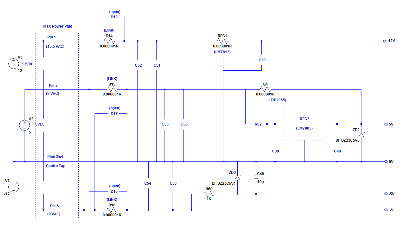
However, the solution proposed here assumes that all four
voltage levels are required and
it is necessary to supply +12VDC, +5VDC and -12VDC to the
computer board, to accomplish this, some modifications to the
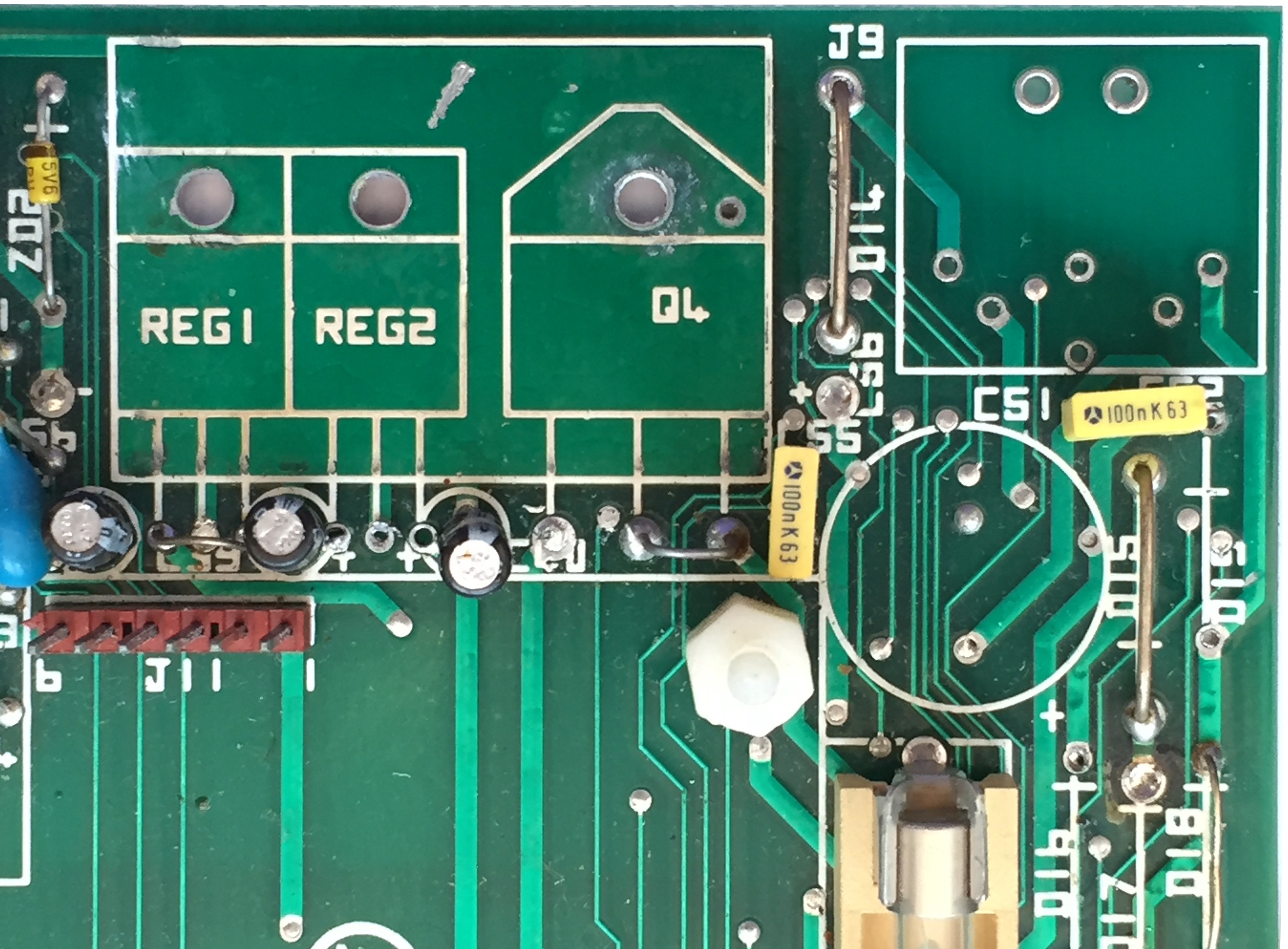
power circuit is required as shown below :
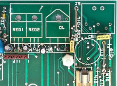
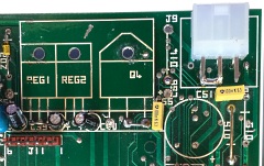
The 6 x regulation diodes, D14 to D18, must be removed, and D14,
D15 and D18 must be replaced by shorting links (shown as resistors
in the
LTspice schematic above).
The 12V regulator (REG1) is removed and a shorting link soldered
between the input and output connections on the computer board.
The 5V regulator (REG2) is removed, the power transistor (Q4) is
removed and a shorting link soldered between the emitter and
collector connections on the computer board.
It is assumed that suitably stabilised DC power supplies will be
used to power the +12V, +5V and -12V rails, so the capacitors
originally fitted should be removed (C38 to C40 and C51 to C56).
R60, C49 and ZD3 are retained to generate -5VDC from the -12VDC
supply. The simplified schematic is shown below :
Power requirements
The MTX computer board was fitted with a 3.15mA fuse for the
+5VDC rail, so, without making any attempt to work out the
actual 5V power requirements, I have assumed that 3A will be
adequate for the +5VDC supply.
The only consumer of -5VDC are the 4116 VRAMs, the
ITT 4116 data sheet gives the maximum -5VDC power
requirement for a single chip as 200uA, giving a total demand
from the MTX of 1.6mA from the 8 VRAMs. (This power is
derived from the -12VDC supply.)
The main consumer of +12VDC on the MTX computer board are the
4116 VRAMs, the
ITT 4116 data sheet gives the maximum +12VDC power
requirement for a single chip as 35mA, giving a total demand
from the MTX as 280mA from the 8 VRAMs.
The cassette port also requires +12VDC and -12VDC and other
potential consumers for these voltages would be the
RS232 board, if fitted, and/or the motor (+12VDC) of an SDX
floppy drive if fitted and powered off the MTX +12VDC rail.
| The suggested power requirements are therefore : |
+12VDC |
+5VDC |
-12VDC |
| Basic MTX, with no RS232 board or
floppy drives |
0.5A |
2A |
0.2A |
| Maximum load from RS232 and floppy
drives |
2A |
3A |
0.2A |
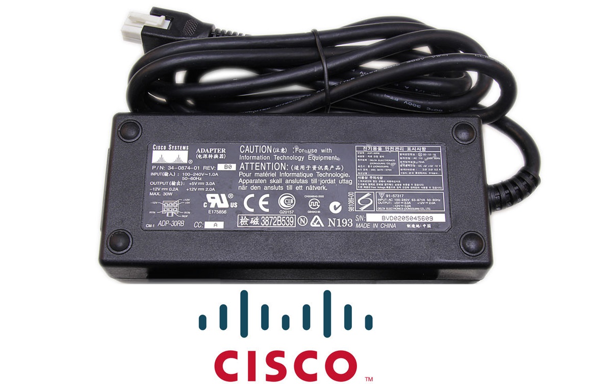
After a bit of "Googling" for ready made PSUs, I came
across a Cisco ADP-30RB (34-0874-01), this supply is intended
for use with various Cisco routers such as
models 506/1700/1720/1721. These supplies are widely available for good
prices from eBay and provide +5VDC at 3A, +12VDC at 2A and
-12VDC at 0.2A (maximum 30W total).
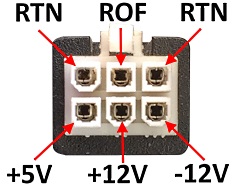
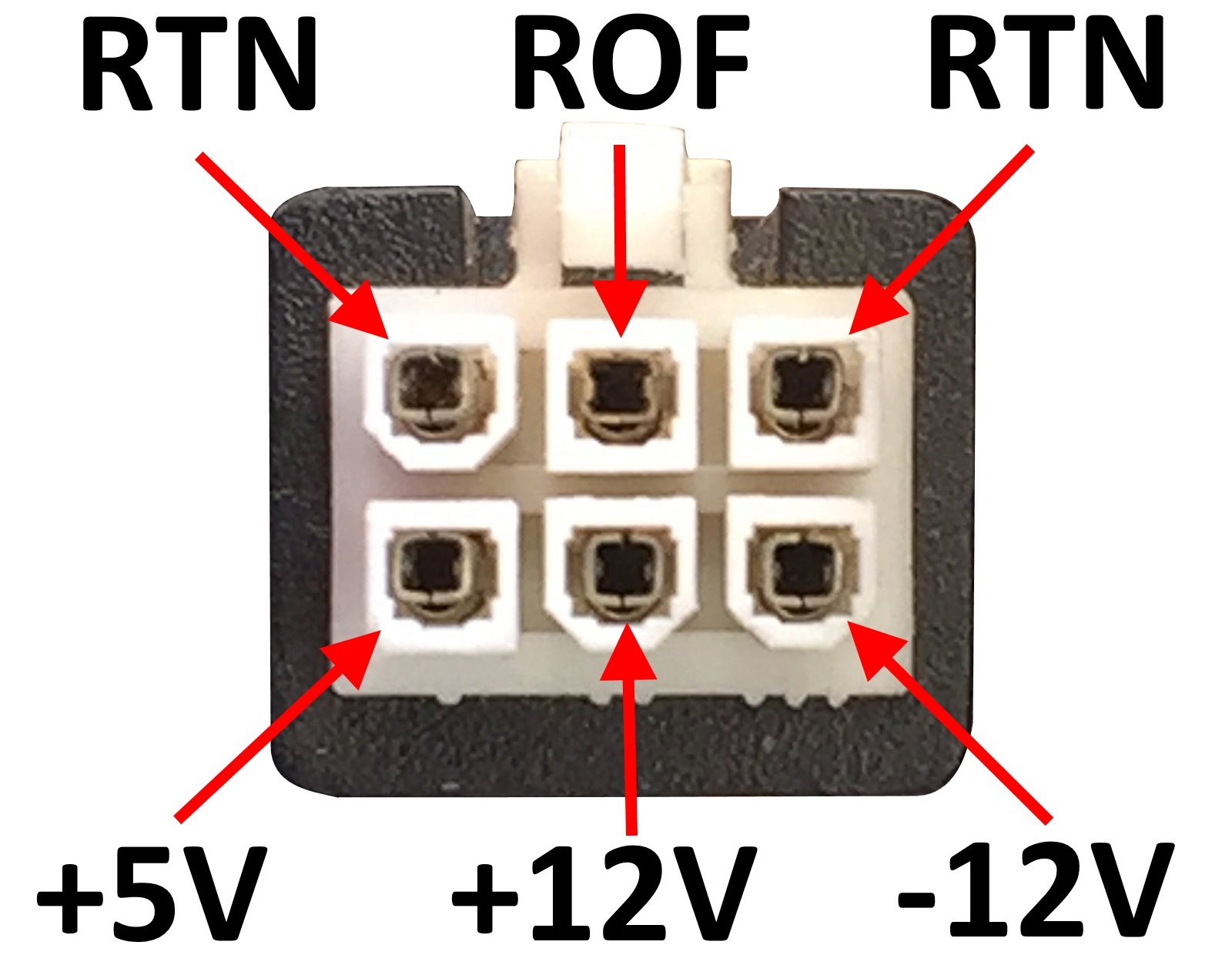
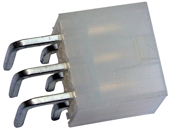
The standard cable on the Cisco
PSU uses a
Molex Mini-Fit Jr connector with the pin-out as
shown.
The voltage and 0V (RTN) pins are self
explanatory, but the ROF pin is worth a mention. The
acronym stands for Remote On/Off,
similar to the way that an ATX PSU is controlled, the
ROF pin must be grounded to turn on the PSU.
(This pin could be permanently grounded to have the PSU
always on, or used to add a power switch to the MTX.) |
 |
Connection Considerations
If you only have a single MTX computer, then connecting DC
supplies via the existing connector on the MTX computer board is
not likely to cause any problems. However, as I have a number of
MTX machines with standard AC PSUs, I wanted to guard against
the possibility of connecting the DC supply to my unmodified
MTXs, and probably more importantly, prevent me from
accidentally connecting an AC PSU to the modified MTX.
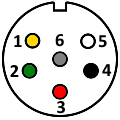
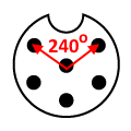
| The MTX power input uses a
DIN connector. |
 |
DIN connectors come in various
configurations, with 3 to 8 pins, the angle between the
first and last pin are commonly, 180o,
240o and
270o.
The MTX connector is a 6-pin, 240o
socket, the numbers shown on the left hand image show
the pin numbering, looking into the plug on the original
PSU lead. |
|
The table shows the nominal AC
voltages fed from the original MTX PSU to the relevant
pin in the socket and the DC voltages required to
replace the AC PSU.
Pin 6 is not connected |
| Pin |
AC Voltage |
DC Voltage |
| 1 |
13.5 ~ |
+12 |
| 2 |
9 ~ |
+5 |
| 3 |
0 |
0 |
| 4 |
0 |
0 |
| 5 |
9 ~ |
-12 |
| 6 |
(n/c) |
(n/c) |
|
| For convenience, here is an
image of the view into the plug along with a mirror
image which shows the position of the pins when looking
into the power socket from the rear of the MTX. |
 |
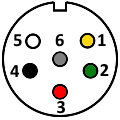 |
| Front of plug |
Rear of socket |
|
| One option to provide some
protection against plugging the wrong type of PSU into a
modified, or unmodified, MTX would be to use a 5 pin 180o
DIN connector for the DC version. With pin 6 missing, an
original MTX AC PSU could not be plugged into the
DC version and the pin angles would prevent the DC PSU
being plugged into an unmodified MTX. This is probably
the easiest solution but I chose not to go that way. |
 |
 |
NB:
The colours shown above are those used in the original
MTX PSU cable and are NOT the same as those used by
Cisco.
The colours used in one particular Cisco
PSU are shown opposite, these are not guaranteed to be
the same for all, if you are going to replace the Molex
connector with a DIN plug, ensure that you know which
voltage is on each core. |
| RTN |
ROF |
RTN |
| Black |
White |
Black |
| |
|
|
| +5 |
+12 |
-12 |
| Red |
Orange |
Green |
|
My DC Power Supply Solution
Manfred Flume donated a couple
of MTX512s to me,
including one
that he had previously converted to use a DC only PSU.
Since most of the power regulation components
had already been removed from this machine, it made a
good test-bed for a DC only power supply project. |
 |
Rather than convert the Cisco
PSU to a 5-pin DIN connector, I decided to replace the
MTX power socket with a mating connector for the Cisco
PSU.
In this photo, you can see the 5-pin DIN
socket has been removed and the holes cleaned up in
preparation for the new socket. |
 |
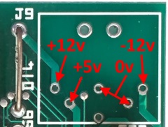
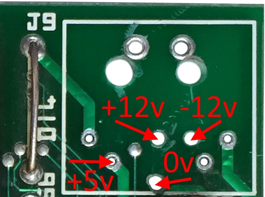
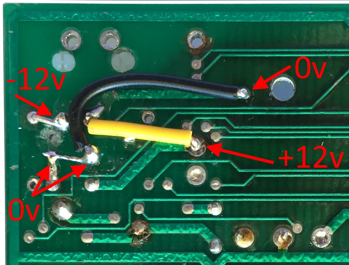
Close up of the socket PCB
connections, annotated to show where DC voltages would need
to be connected if using the standard DIN PSU socket.
You could, of course, just remove the DIN socket and
solder wires from an external DC PSU directly to the
computer board, but this would mean that the PSU was
permanently connected and you would also need to
consider including some strain relief for the cable -
though this could be as simple as putting a tie-wrap
though the DIN connector fixing holes. |
 |
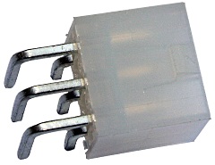
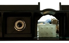
| The replacement socket for the
Cisco PSU plug. Obviously, the pins are not going to fit
the PCB without some work ! |
 |
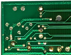
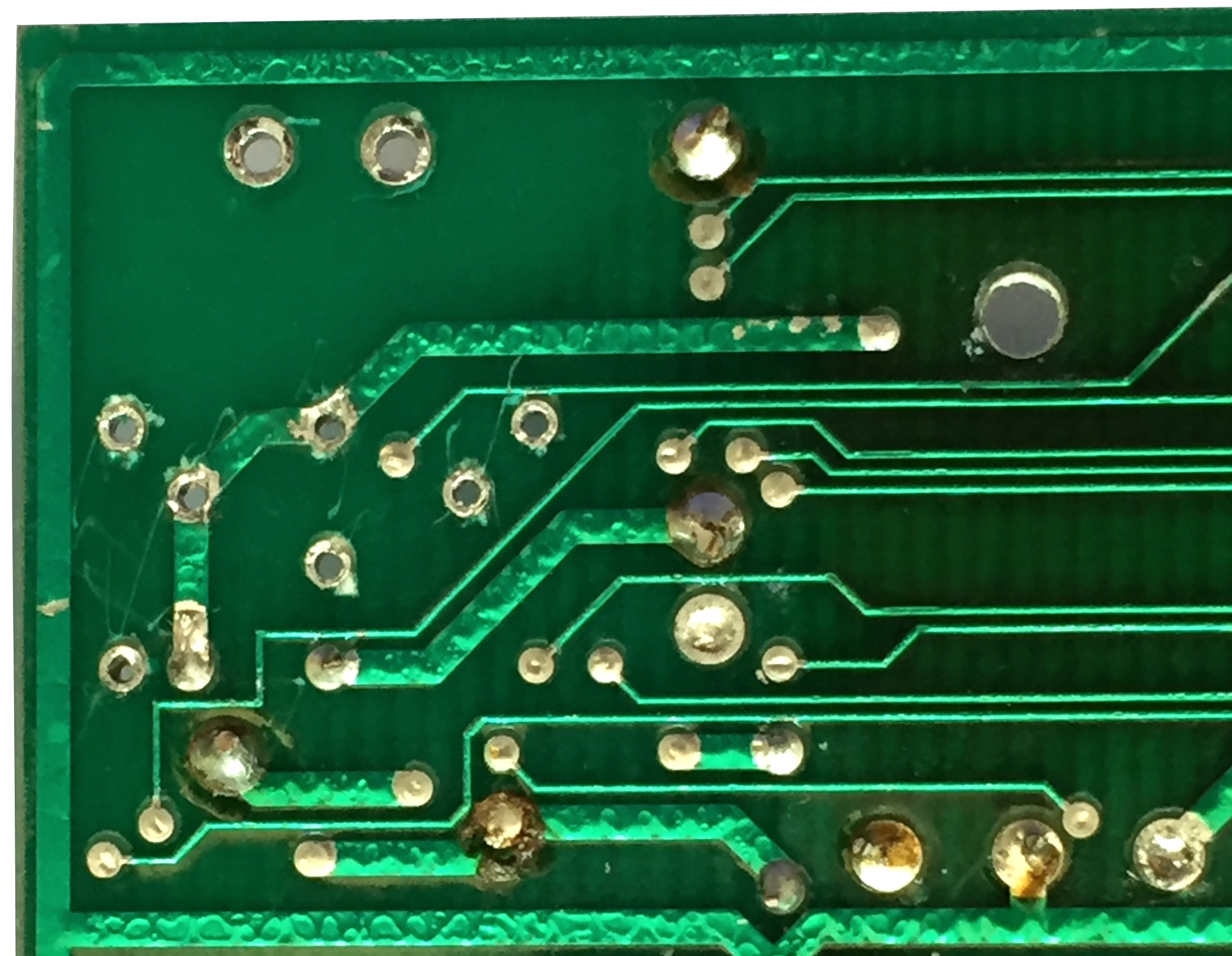
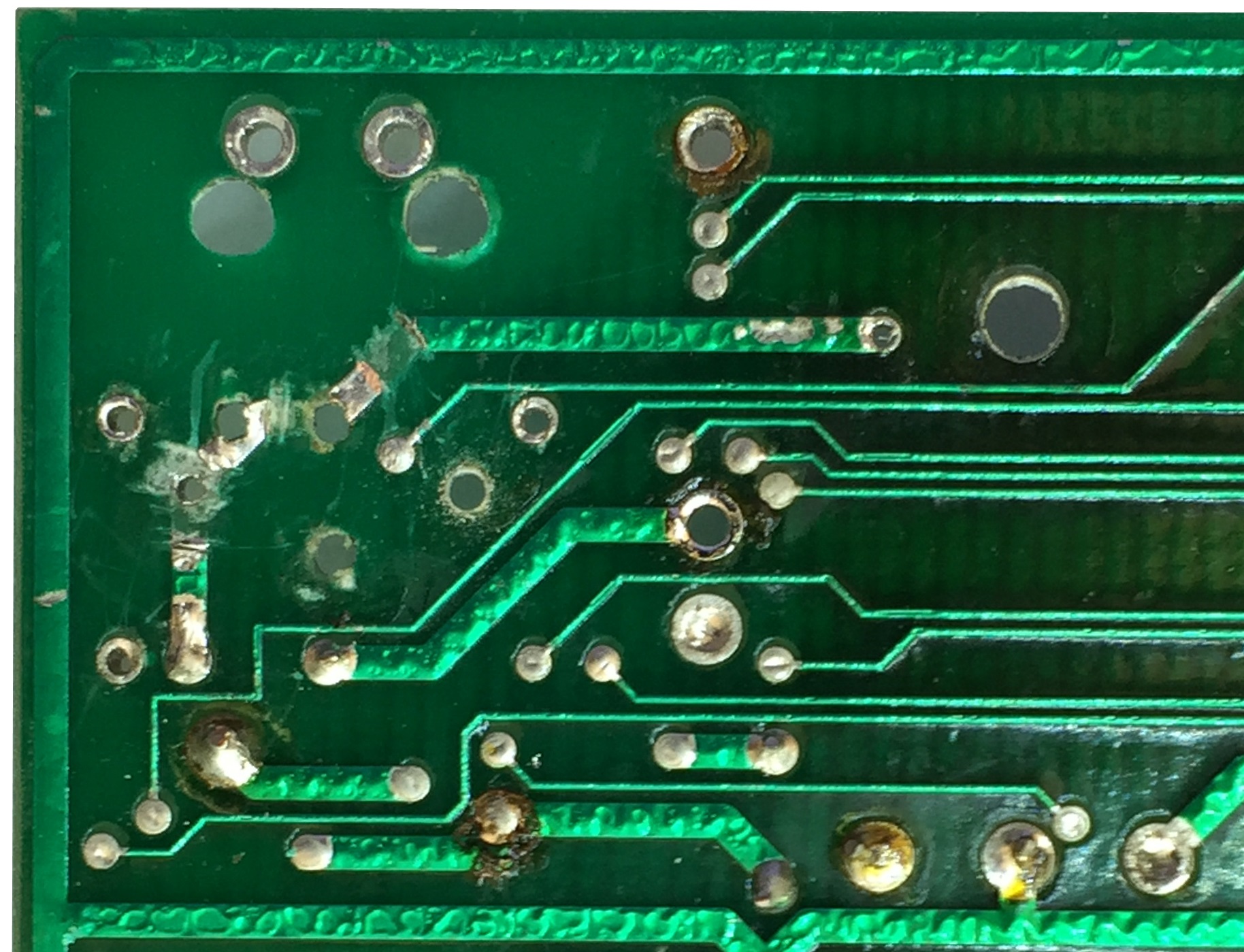
Solder side of the PCB,
there is enough free free space on the PCB to
drill a couple of holes for the socket locating lugs,
but, as might be expected, the Cisco socket pins do not
fit the tracks on the PCB.
Modifying the PCB to
allow the Cisco power socket to be mounted requires that
a couple of the existing tracks are "butchered". |
 |
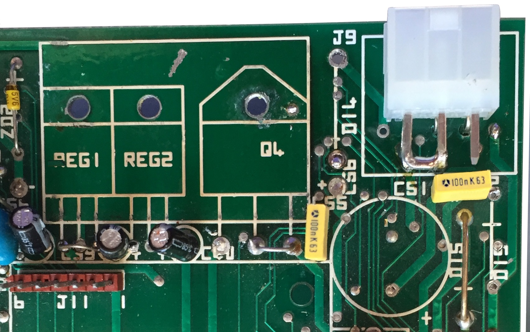
Minor modifications made to the
PCB :
2 x 3mm holes made for
the Cisco socket mounting lugs
Existing through hole barrel expanded for the
+12v pin
Additional hole drilled through the PCB
for the -12v pin
Existing through hole barrel
expanded for the ROF/0v pin |
 |
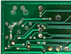
The +12v
and -12v pins penetrate the 0v trace on the solder side
of the PCB.
I cut the trace to isolate the
+/-12V signals, leaving a small amount of copper
adjacent to the new pins to give a good connection
between the pin and new patch wires that were required.
The small track right in the middle of the action is
the RELCPMH signal, which just happens to be routed
under the PSU connector ! |
 |
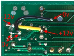
The
combined ROF/0v pin is connected to the 0v traces on
either side of the cut trace (black wire and wire link).
The +12v (yellow wire) and -12v (wire link) lines
are patched as shown |
 |
Replacement socket fitted
It is not clear from
the photo, but the left hand RTN pin and ROF pin are
linked together at the rear of the socket, the ROF pin
is used to connect to the 0V trace on the PCB. The RTN
pins are not connected to the PCB.
The 5V
connection is hidden below the upper row of pins, but
connects to the 5V trace on the PCB
|
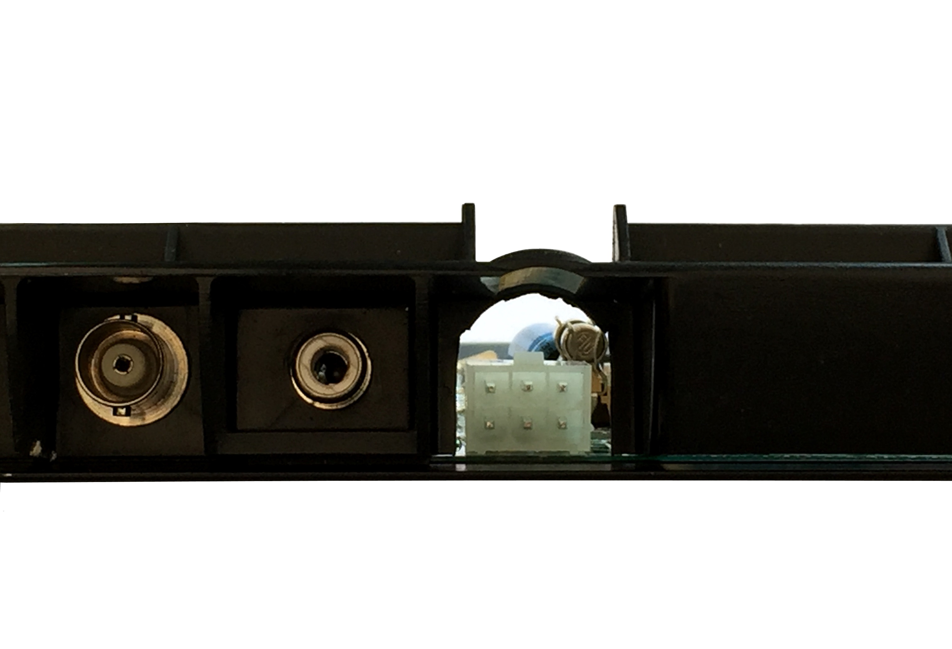
 |
The round hole that the
MTX power connector would normally pass through needs to
be opened out to allow the Cisco plug to pass though it.
This creates a slightly weaker plastic filler panel,
but once it is refitted to the MTX, it is fine. |
 |
|


