|
My Video Wall
Hardware
|
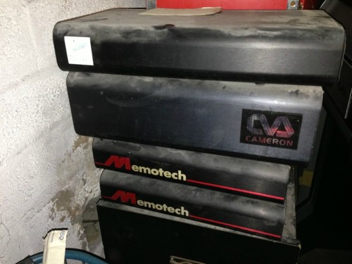
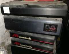
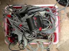
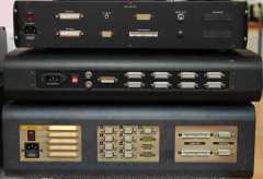
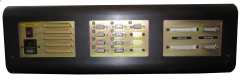
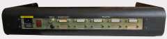
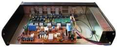
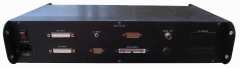
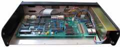
| This photo is of Video Wall hardware, listed on ebay in 2013
as a "Memotech Video Wall Controller 1980s / 1990s".
The advert described the item as having the 4 "control boxes"
shown in the photo and advised that the seller believed that the Video Wall did
not have a computer with it (the system being totally self contained).
After I had bought it, the seller found two additional "control
boxes" and an MTX512S2 which he generously threw in with the other
parts and delivered it all to me for no additional charge - thanks
very much Kenny!
[Although these items were bought as a what the seller believed
to be a complete system, the components appear to be from two Video
Wall systems.] |
 |
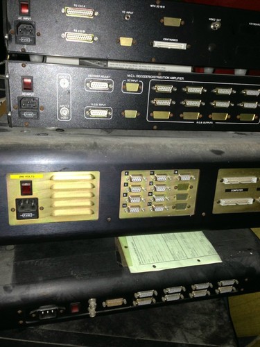
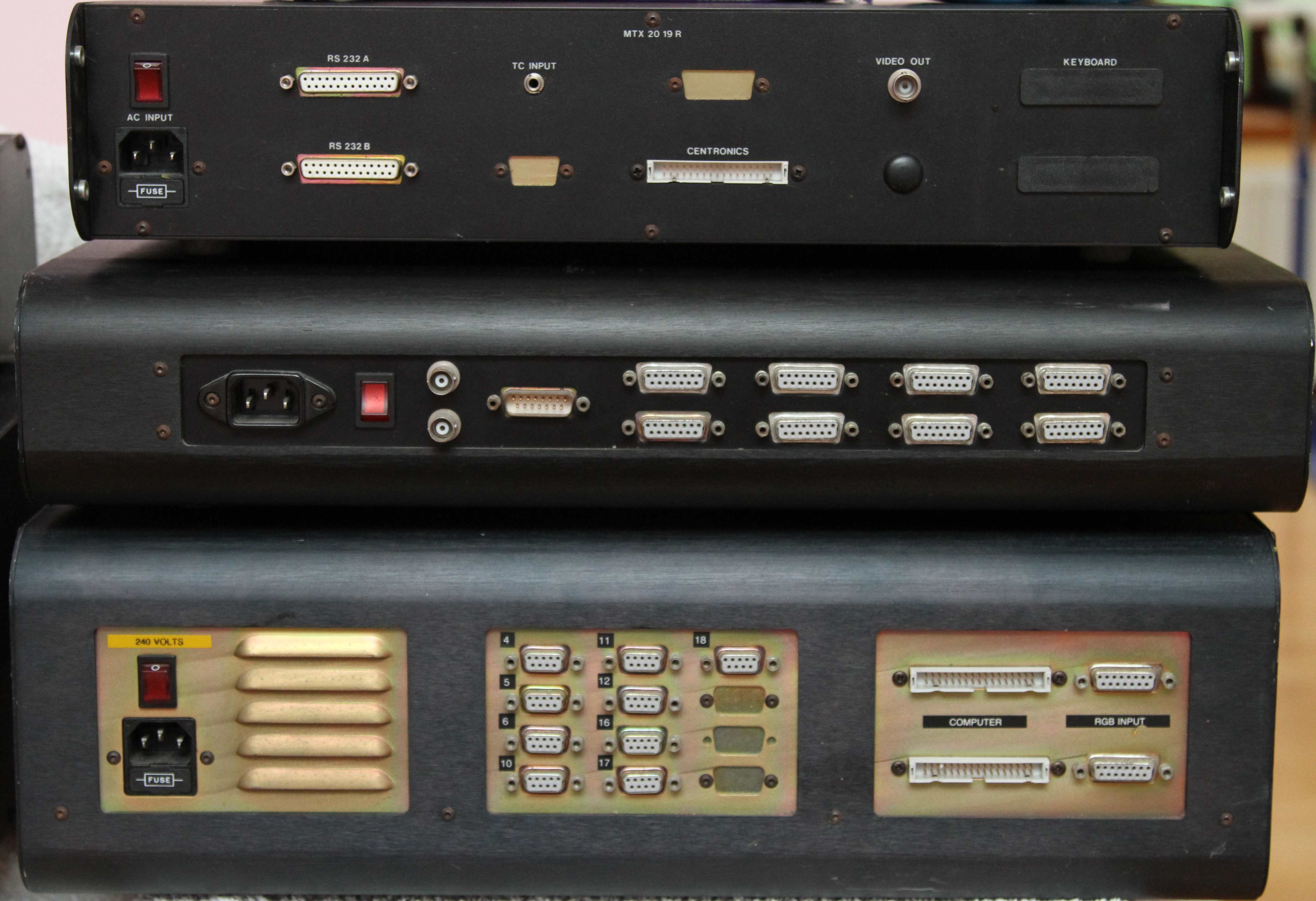
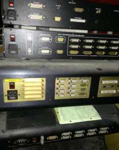
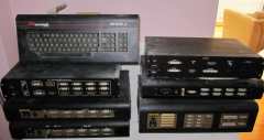
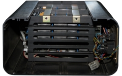
| This is the rear view of the four "control boxes"
initially
included in the auction. The two bottom "boxes" appear to be
similar to the two modules that make up Mike
and Peter's Video Wall systems, these
are described in the Cameron Video
Wall manual and summarised on my
MTX Options page.
The larger of the modules is the Video Wall controller
itself, this houses the majority of the electronics, including the
Frame Memory Buffer boards. In the Cameron manual, the controller is
shown as having 8 monitor output connections, this one, like Mike
and Peter's, appears to have 9.
The bottom module appears to be a Video Decoder
module, this decoded composite video inputs and output RGBS to the
Video Wall controller.
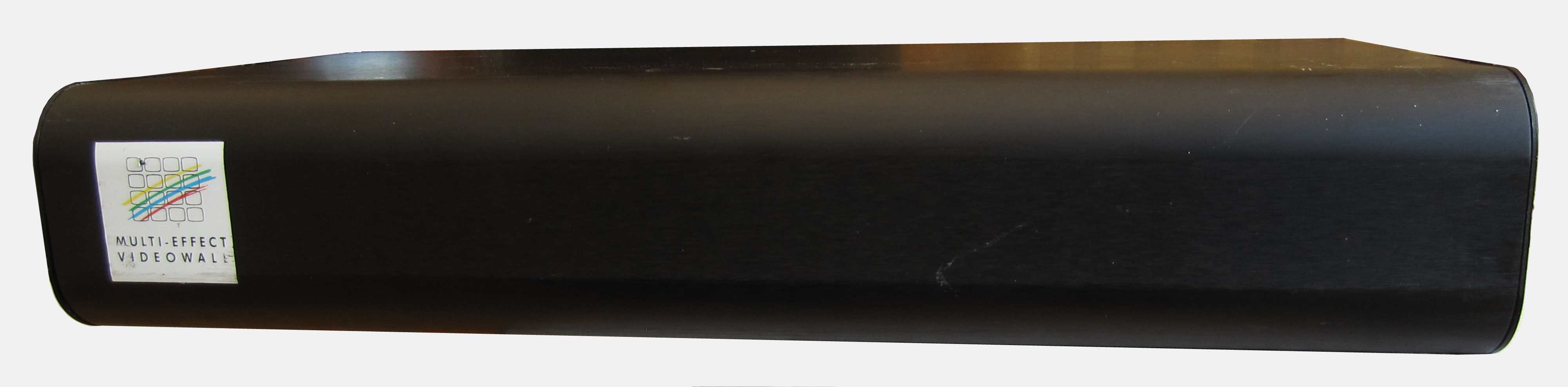
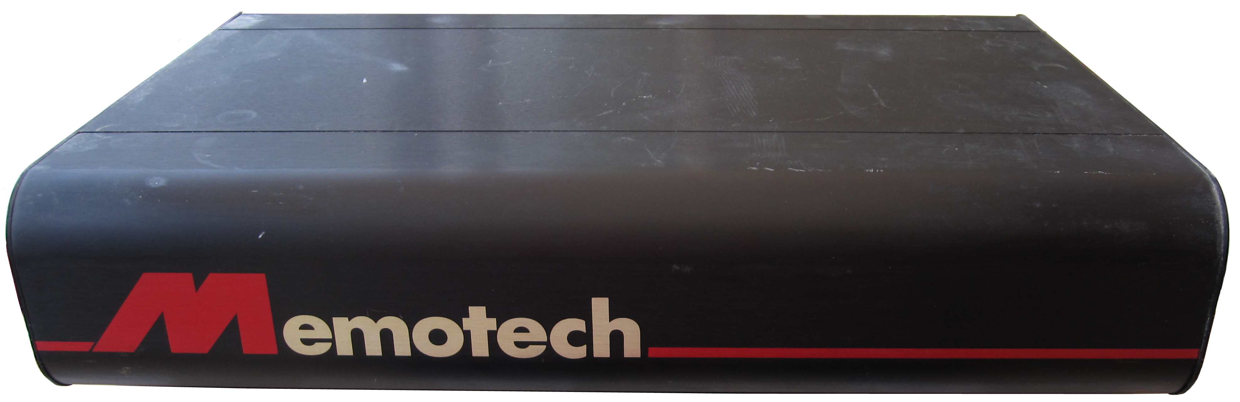
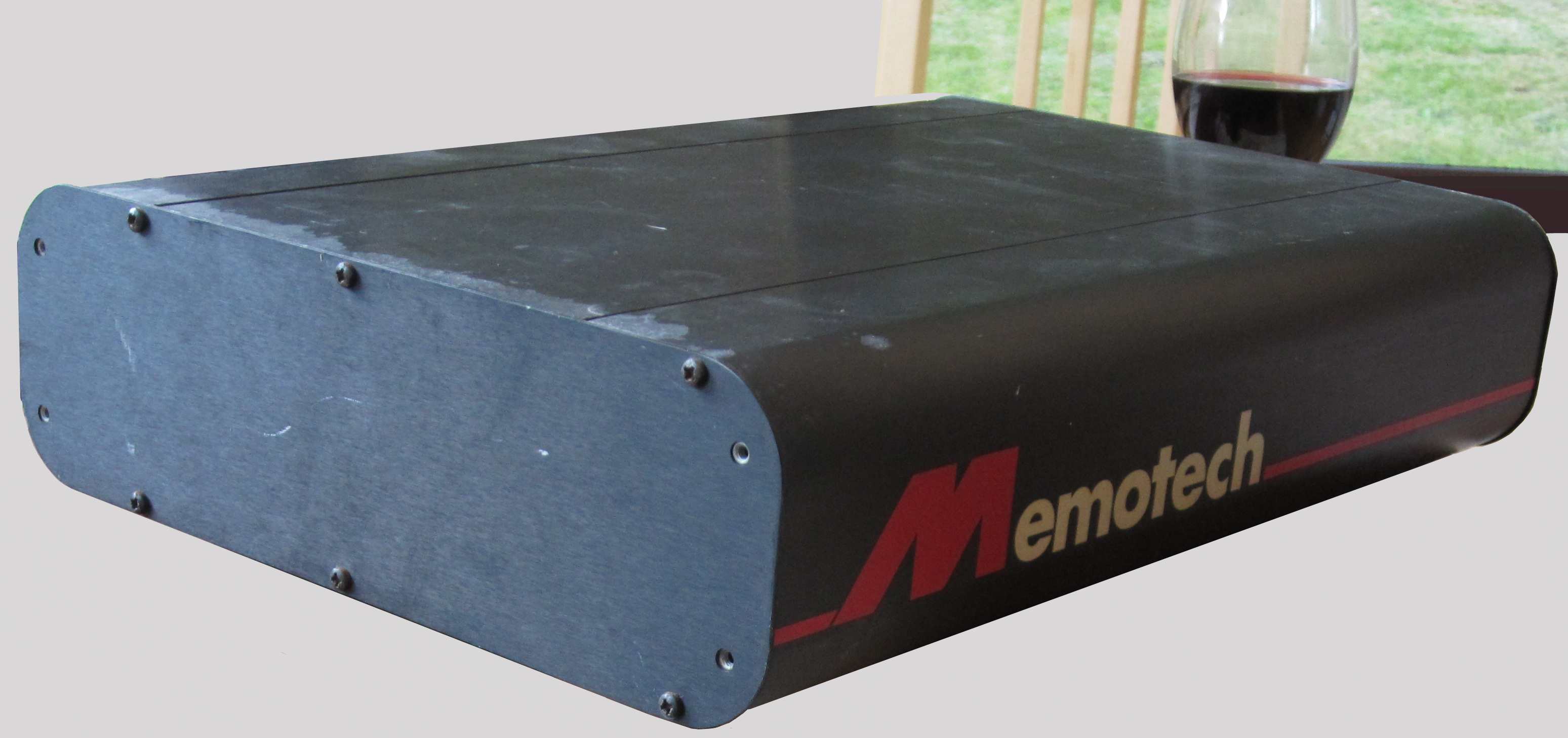
The two modules at the top of the photo have the large
Memotech logos on the front, and at this point, were
unrecognised - by me anyway. |
 |
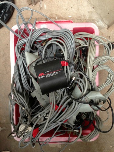
| Although Kenny had bought the Video Wall as complete
and working, he had never actually tried to run it, but thought he
had the interconnecting cables etc.
Part way through the auction, Kenny found this crate with a host
of video and ribbon cables, as well as an MTX computer PSU. |
 |
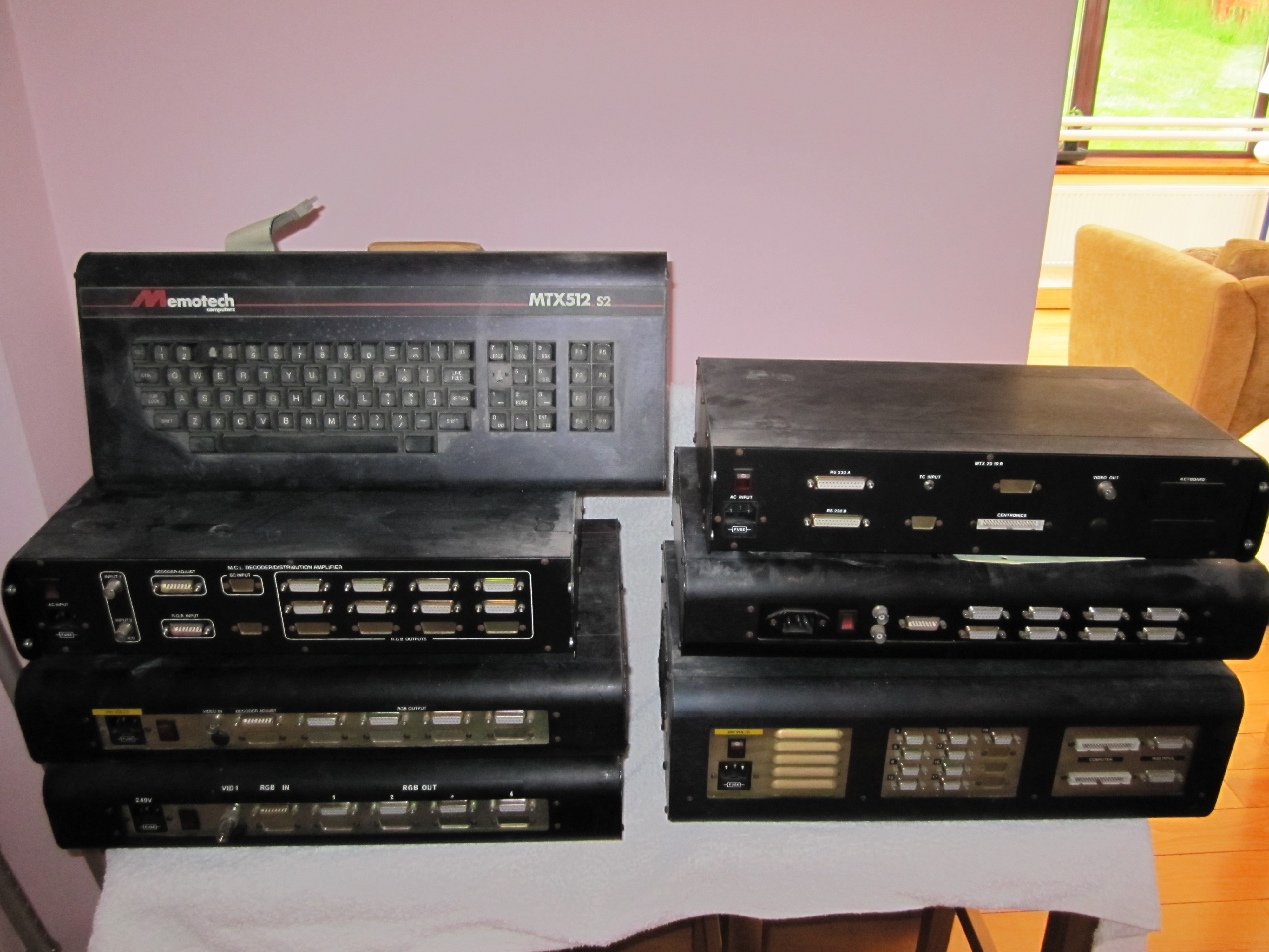
| Wow !! The kit that actually arrived! (not including
the cables) Apologies for the poor quality photo, I will take more
once I get the items cleaned up a bit, they have been stored in a
workshop, undisturbed, for the past ten years or so, and are
somewhat dusty! |
 |
|
Close up / detailed photos - the full size
pictures are quite large! |
|
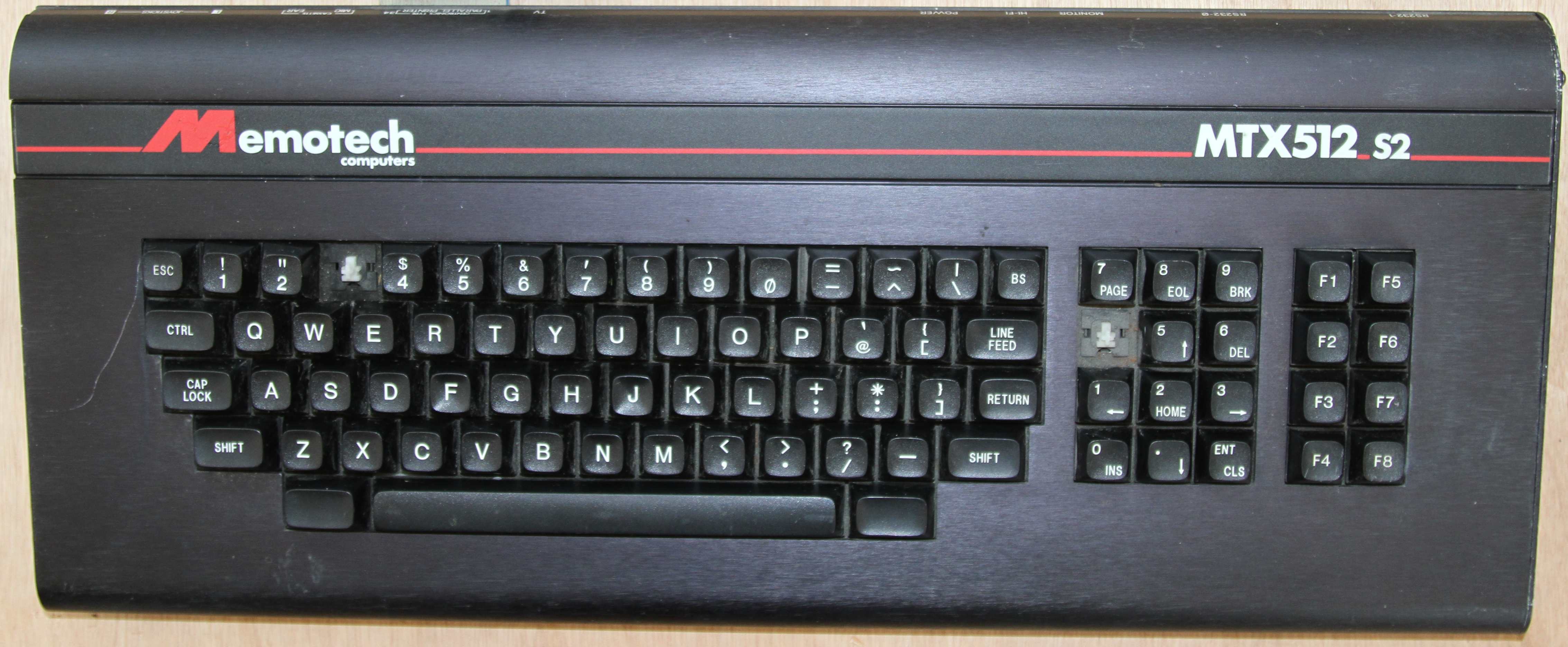
Computer - MTX512S2
(Working : missing two key tops) |
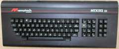
| The MTX512S2 computer used to control the Video Wall
system. It looks to be in reasonable condition, but unfortunately,
it is missing a couple of keys, "3" from the main keyboard and "4" from
the numeric keypad, the keyboard itself feels very good though. |
 |
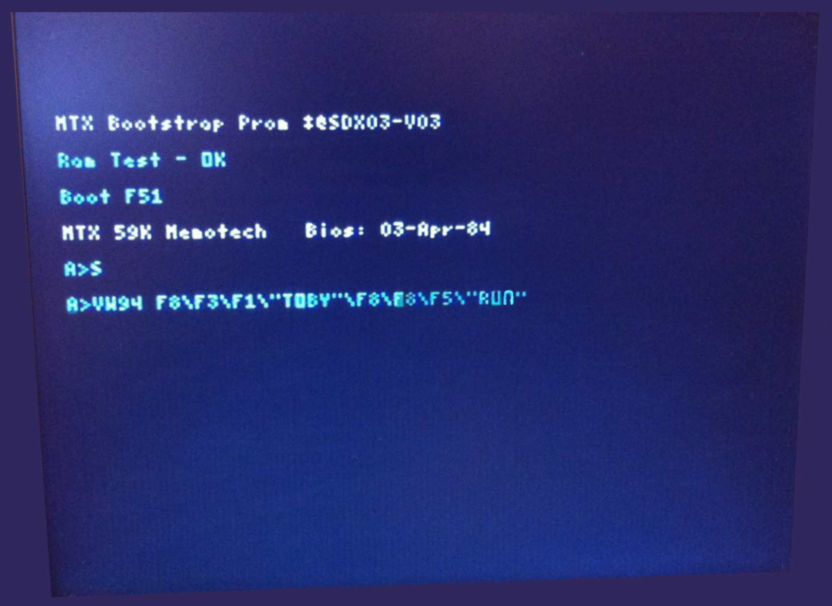
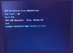
| Pushing the resolution of the graphics processor to
its limit, the MTX512S2 starts up in 56 column text screen mode and
boots into CP/M to run the Video Wall software.
(A description of his modifications to the SDX Boot ROM to allow
it to run the Video Wall software from ROM are described on
Andy's
software page).
This screen is only displayed for the briefest of moment - taking
lots of iPhone snaps to get this poor quality image! |
 |
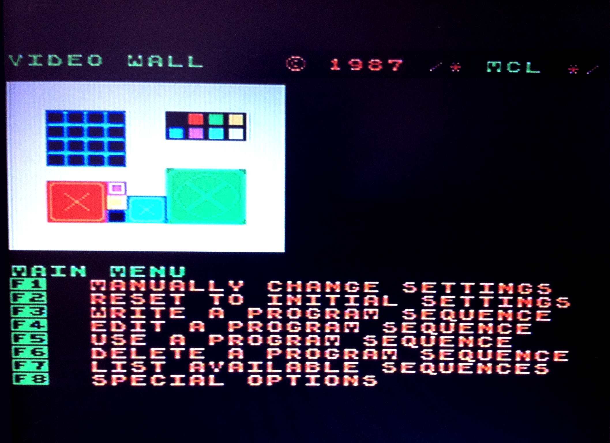
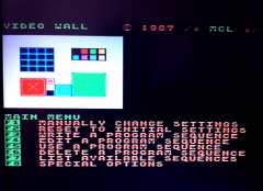
| And just to show that it actually works, this is the
Video Wall software Main Menu - after pressing <ESC> (with no
hardware connected, the software initially displays a "No Sync"
warning and prompts you to hit <ESC> to continue). Although you
would obviously not be able to drive the Video Wall at this point,
display sequences could be created, edited, etc. |
 |
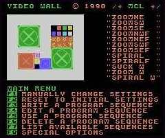
| This is a better quality capture (from
Andy's MEMU page)
showing the Menu more clearly - this is from a later software
version than mine.
This version of the software allows you to drop into MTX BASIC if
you quit the Video Wall application - mine reboots CP/M and reloads
the Video Wall system. |
 |
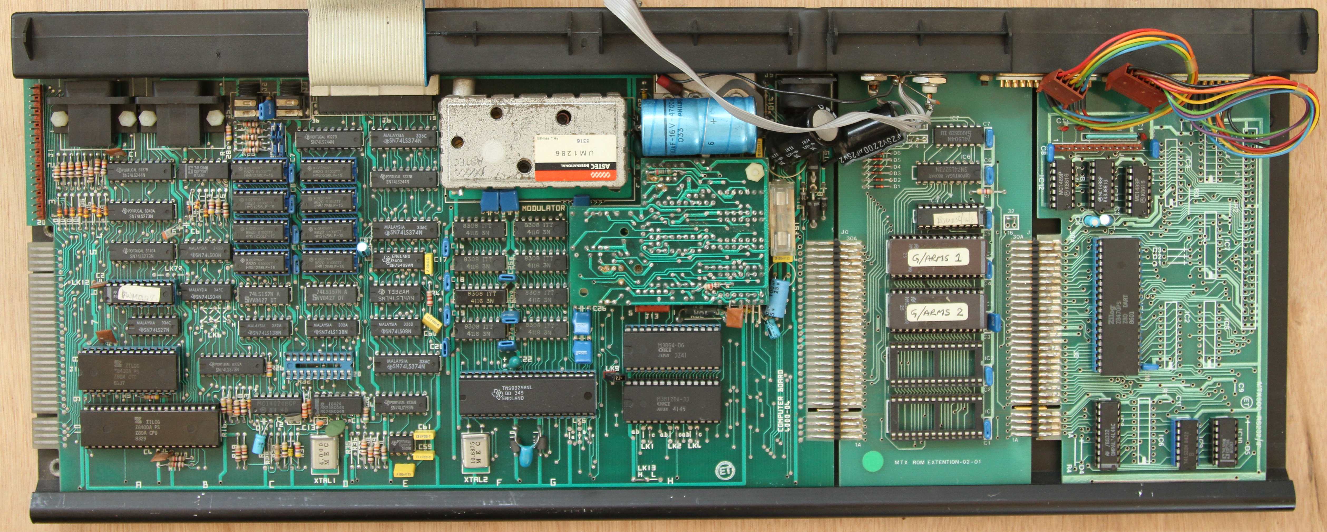
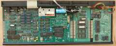
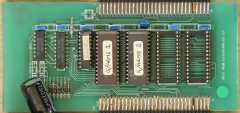
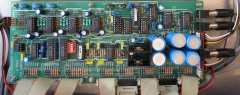
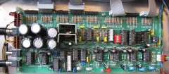
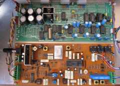
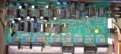
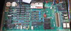
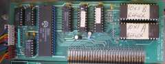
| The internals of the MTX512S2.
From left to right, the 4000-04 computer board, the Video Wall
ROM board and the RS232 interface board. |
 |
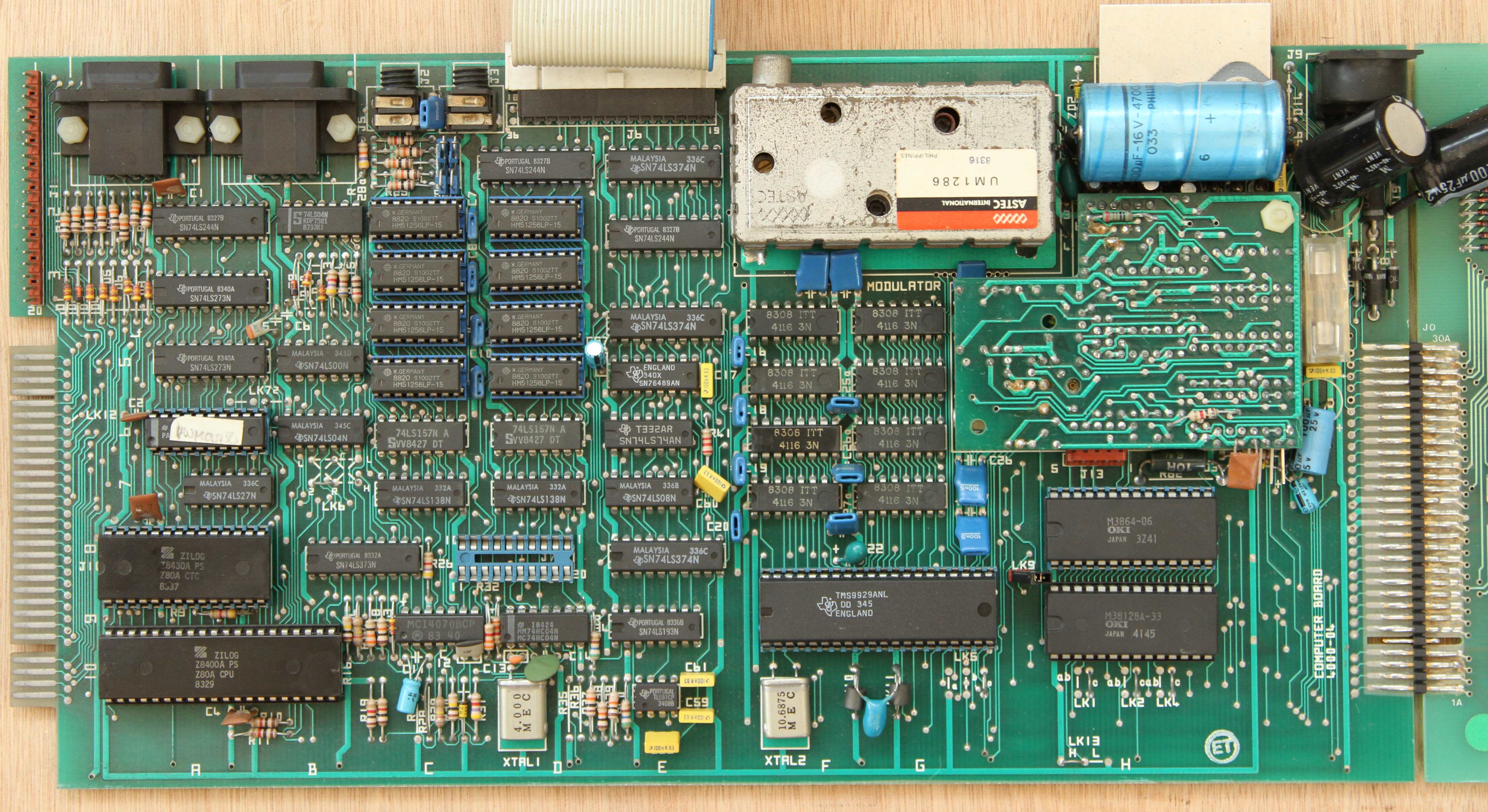
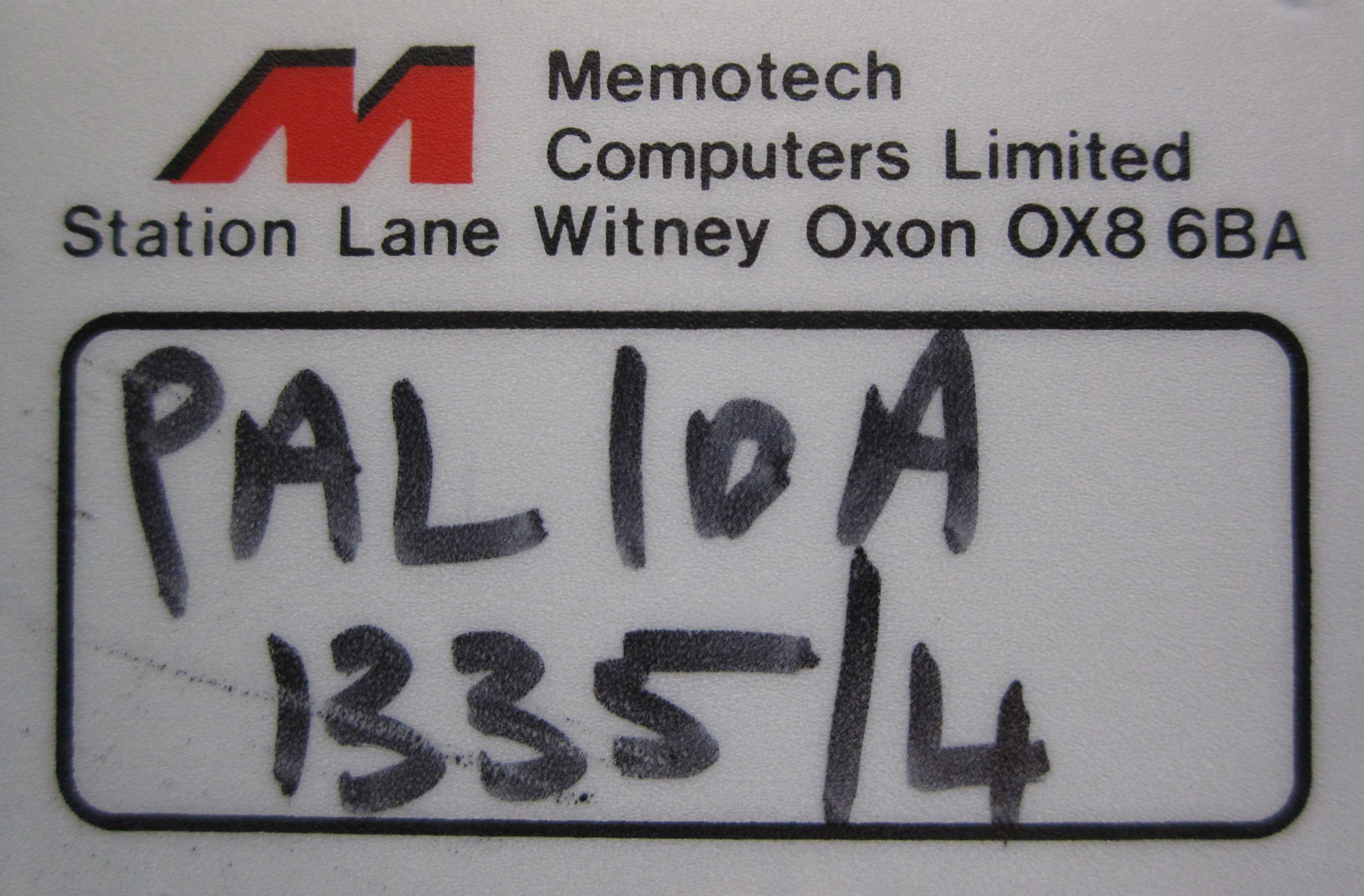
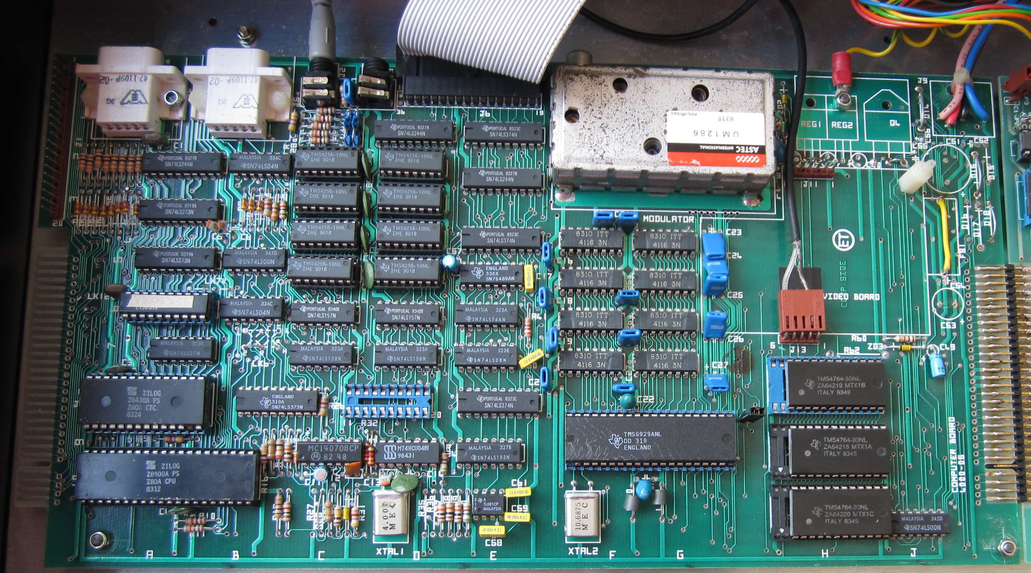
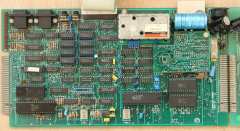
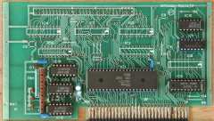
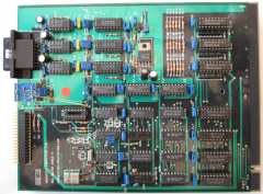
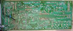
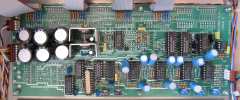
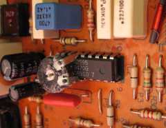
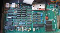
| The computer board.
The obvious differences from an original MTX are the socketed
256k RAM chips, the modified PAL (the chip on the left with the white label used
for memory decoding) and the second black capacitor at the extreme
right hand side of the board, this has been fitted in place of "D19"
fitted to the
earlier MTX models. |
 |
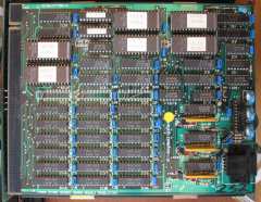
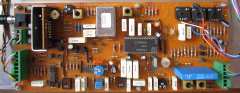
| The ROM board containing two 32k ROMs holding the
Video Wall software. This allowed the Video Wall to operate without
the disk drive that was required for earlier versions of the Video
Wall. The ROM card has also been modified with additional yellow
wiring. |
 |
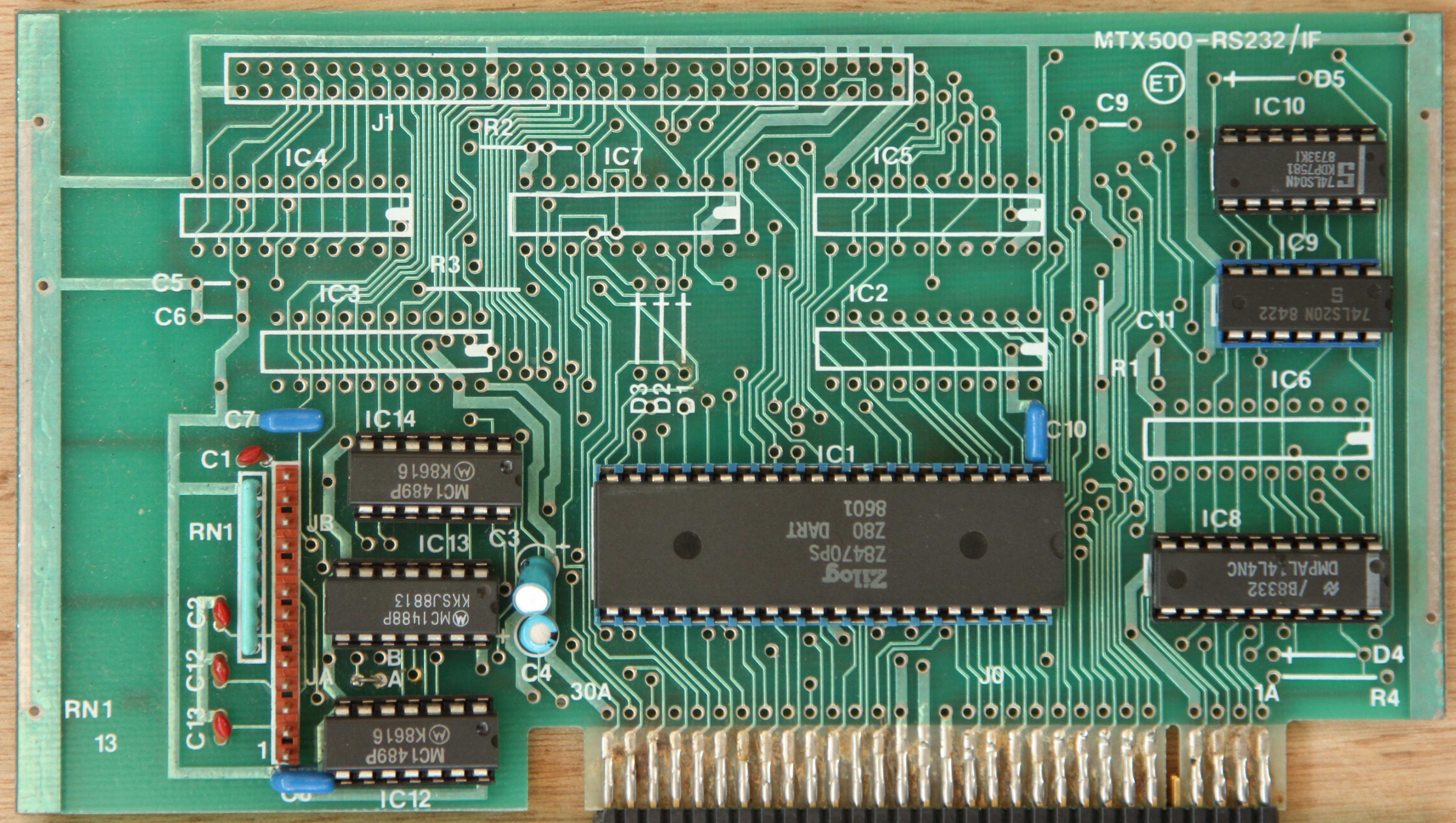
| The RS232 Interface board, this example has been
fitted with the necessary chips to support the two available RS232
channels.
The rest of the board is unpopulated and was designed to hold the
additional components and IDC header for the interface to the, by
now discontinued, FDX. |
 |
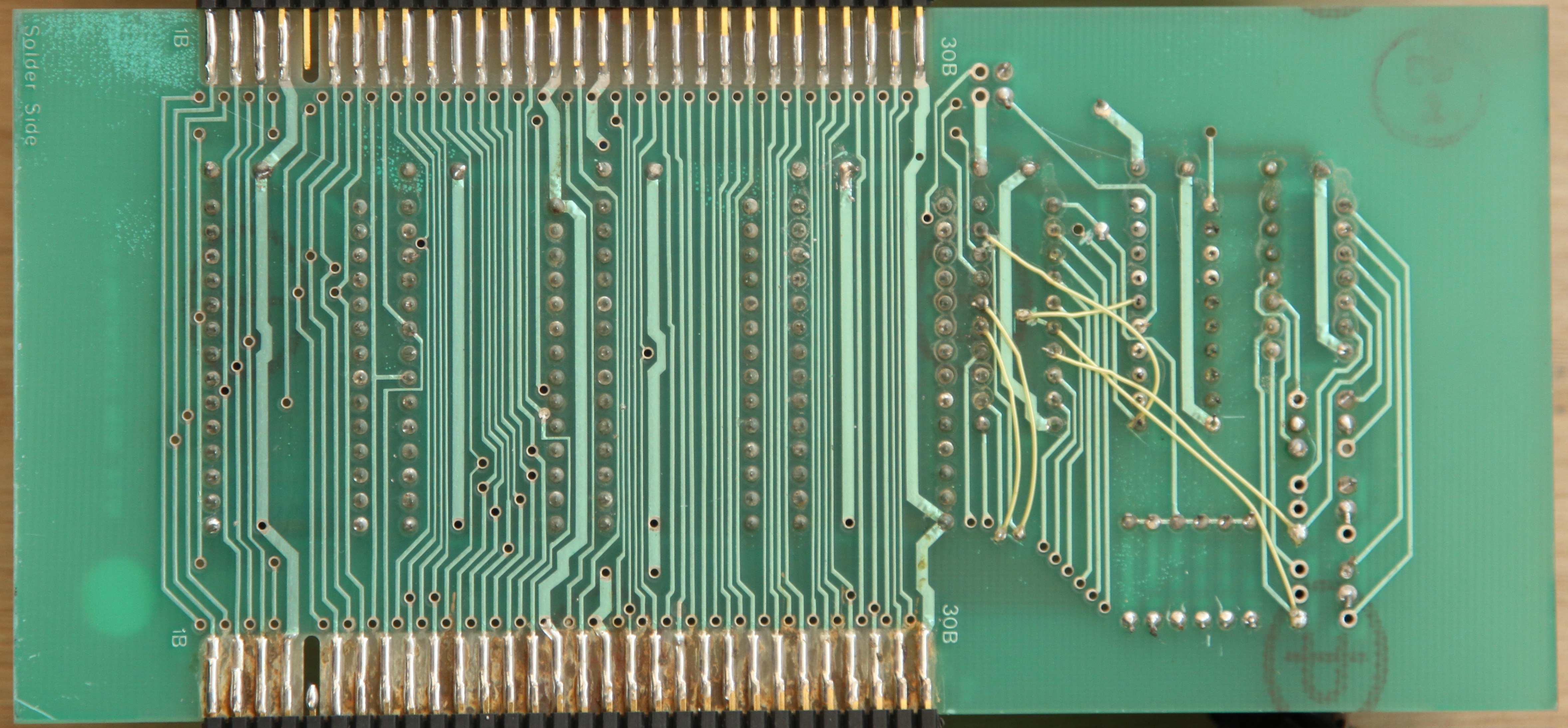
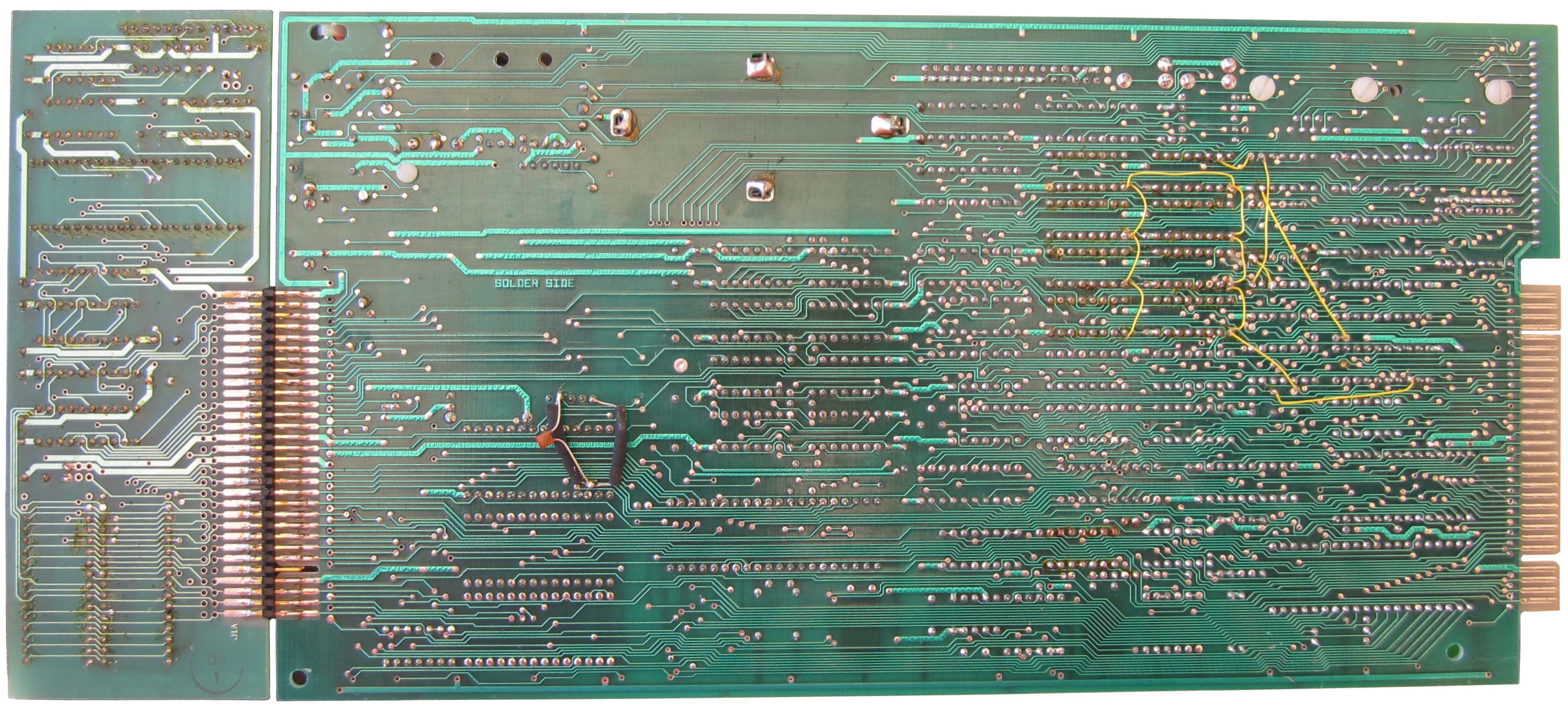
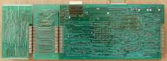
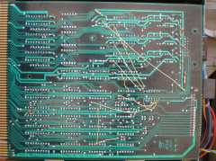
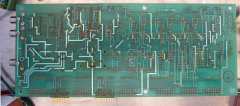
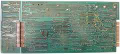
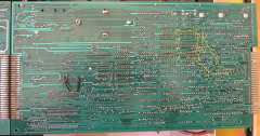
| Solder Side of the MTX512S2 computer, showing the
RS232 Interface board, the Video Wall ROM board and the main
computer board. You can see that both the ROM and main computer
boards were modified with additional yellow wiring. |
 |
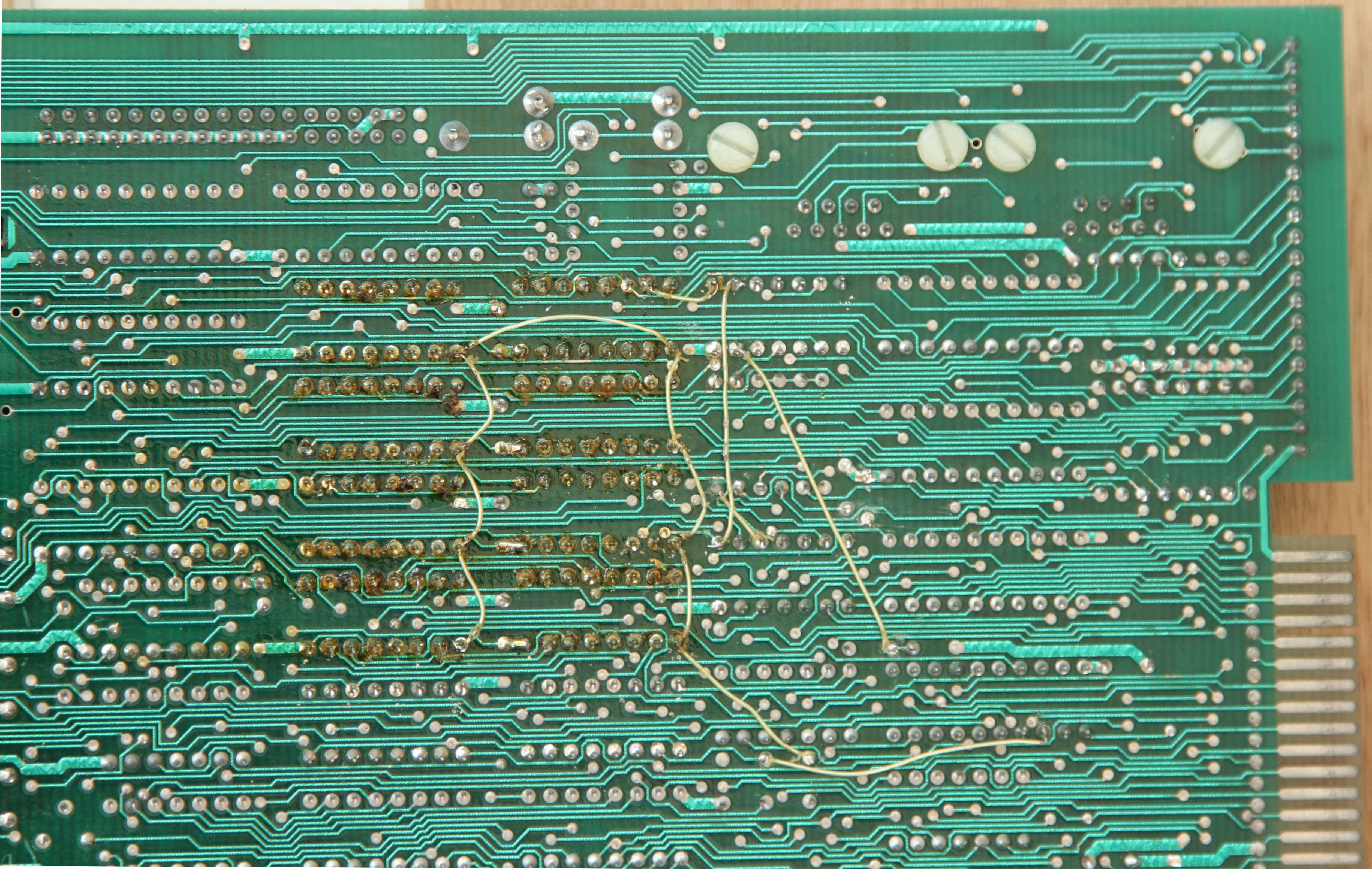
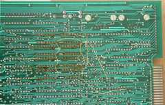
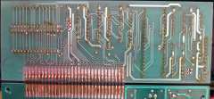
| Close up of the yellow wiring for the RAM, this was
required to allow more than 64kbytes of memory on the computer
board. Andy has a complete description of the MTX series RAM
configurations in the Memory Investigations section of
his hardware
page. Only 64k is visible to MTX BASIC and in CP/M mode, only
208k is useable, with 64k for CP/M and the remaining 144k was normally used as a RAM disk. |
 |
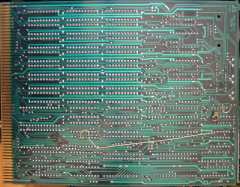
| Close up of the ROM board, also showing additional
yellow wiring modifications. |
 |
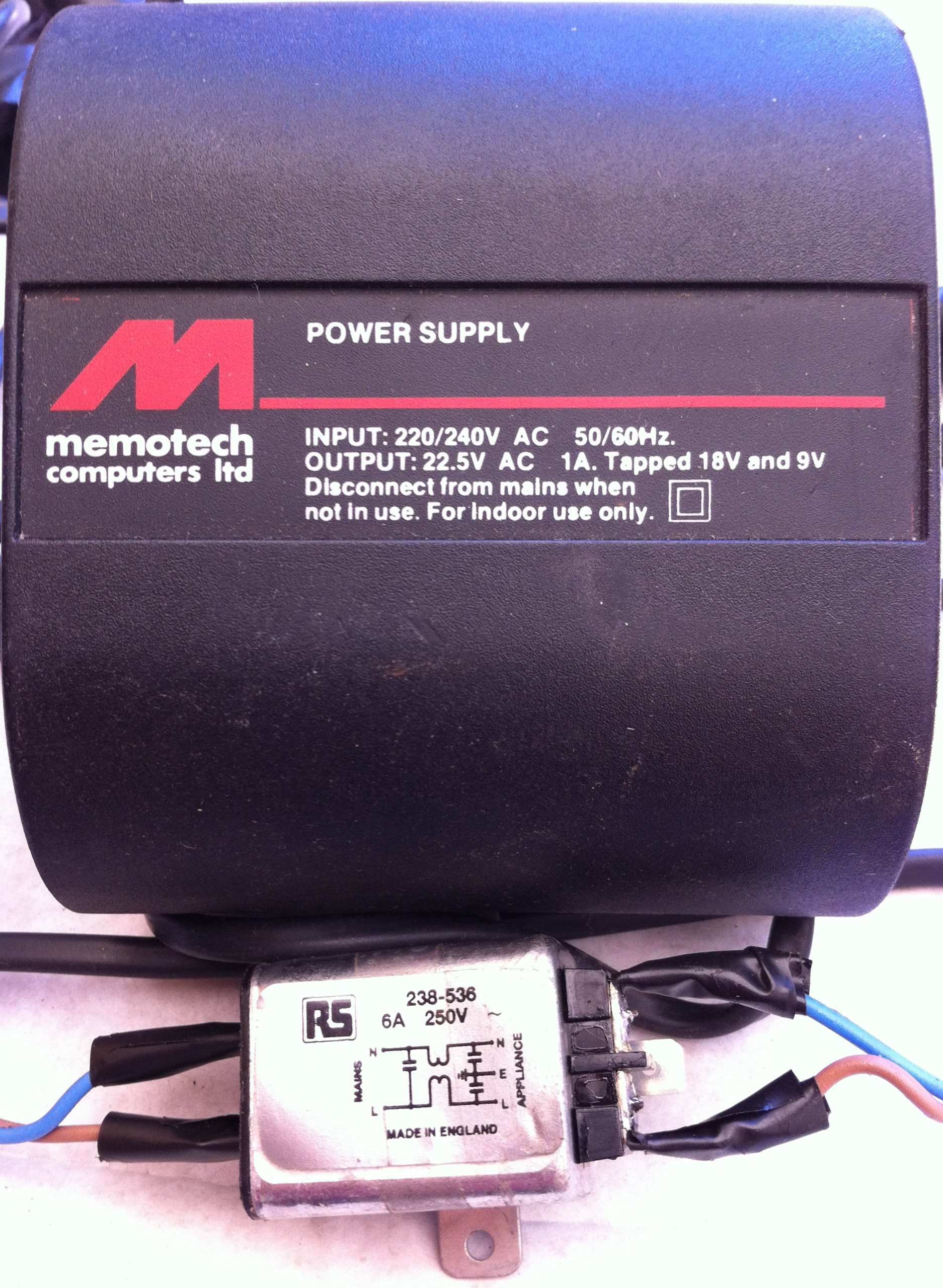
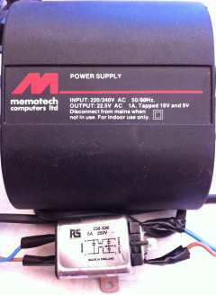
| The PSU for the MTX512S2, it is the standard PSU
supplied with the later model MTXs from Memotech Computers Limited
and has output voltages in the expected range. (See the
PSU page for details - this one
is listed as "ds5"). There has been a clumsy attempt
to fit a noise suppression filter in the cable between the 13A plug
and the PSU. The filter was wrapped with insulating tape, with the
tape removed, you can see that the filter does not have an earth
connection - probably because the PSU itself does not require an
earth connection and finding one was "too hard".
The PSU is "double insulated" - signified by the
symbol on the label :
|
 |
(
Double Insulated - IEC Appliance Class 2 )
i.e., no connection to protective earth is required |
The lack of an earth connection means that the
filter doesn't !
|
 |
|
The Video Wall
Hardware
|
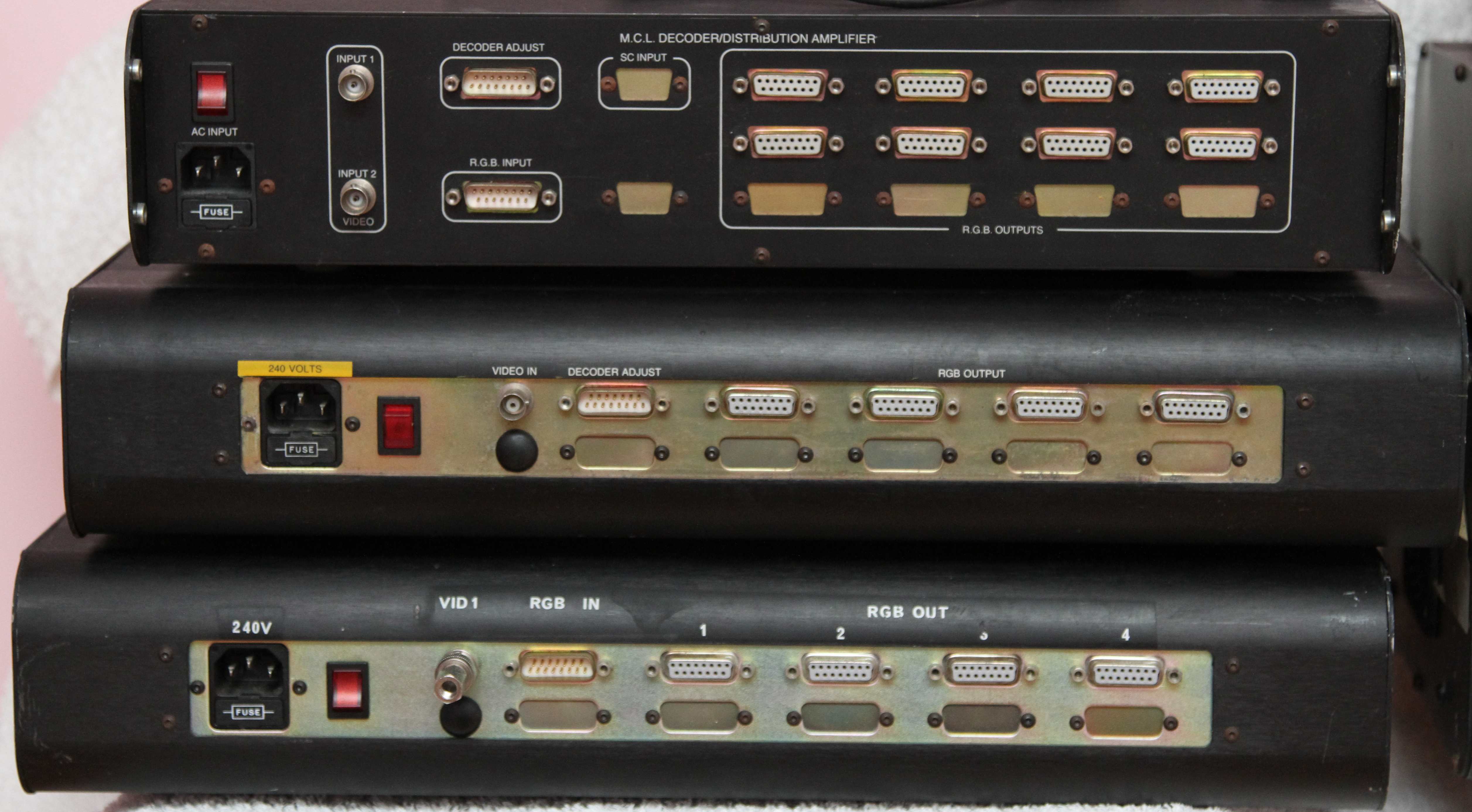
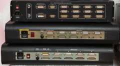
| As noted above, the bottom two modules in this photo
are a Video Wall Controller (DDFS) and a Video
Decoder / Distribution Amplifier. I originally thought that the top module
was a component of a Reflex
Touch Controller which would have connected to the RS232 port of the
Video Wall computer. [A Reflex
Touch Controller had a keypad that enabled the operator/DJ
to use “quick action” buttons
to initiate any of the video sequences stored in the computer
without having to
use the computer keyboard.] |
 |
| The remaining three modules appear to be slightly
different models of Video Decoders, the bottom two look like cut
down versions of the one in the photo above and the top module,
labelled "Decoder/Distribution Amplifier" looks like an expanded
version. |
 |
|
The Video Wall Controller - DDFS
(Distributed Digital Frame Store)
(Had a faulty PSU, now
replaced with a Micro ATX PSU) |
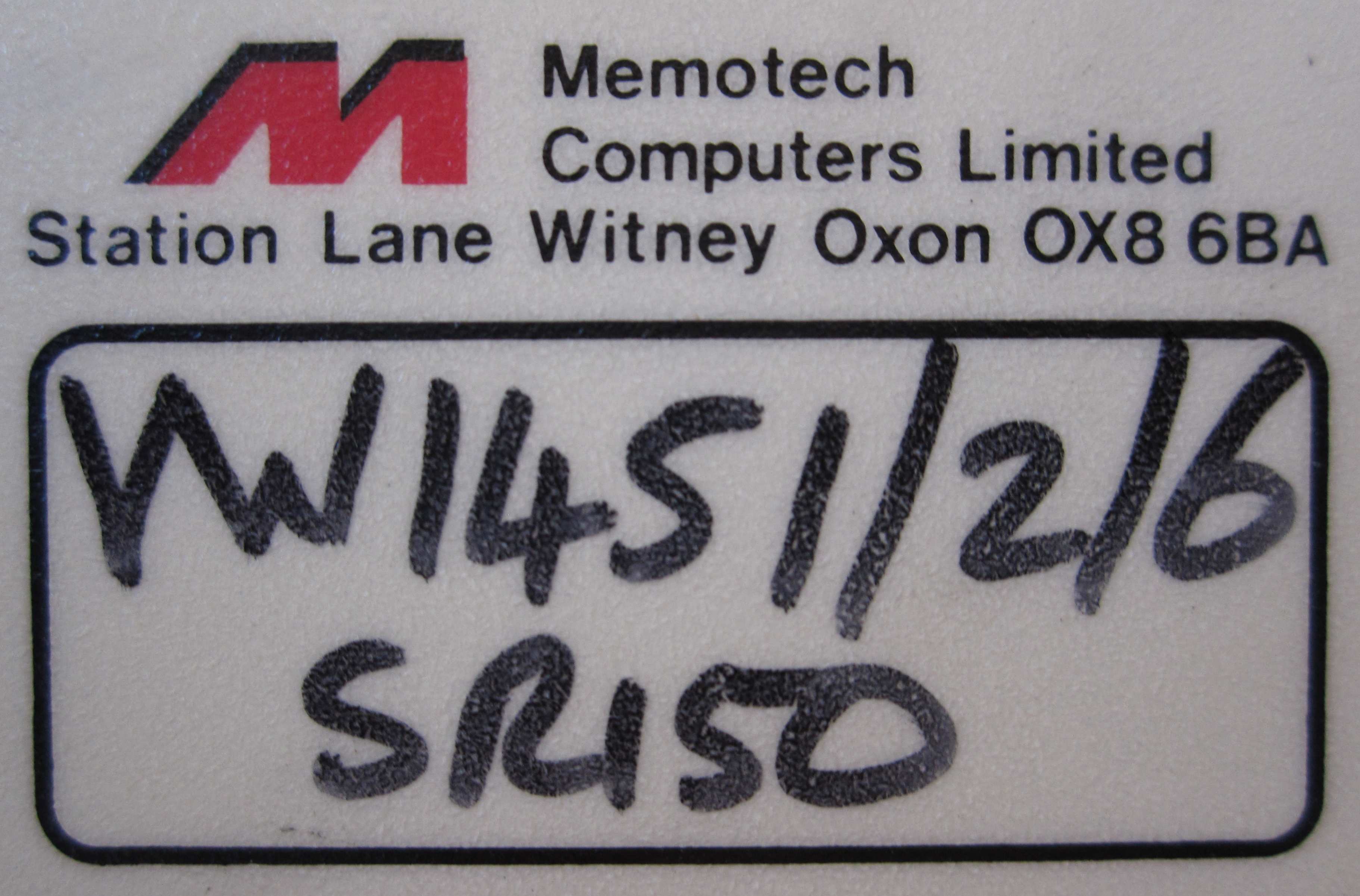
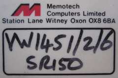
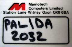
| The Serial Number label from the main Video Wall
Controller (DDFS). Obviously, not a very interesting photo
in itself, but it would be nice to know what information the serial
number held. Probably Video Wall serial number 1451, but what the
"/2", "/6" and "SR150" meant, I don't know. Based on the
information in
Andy's
Video Wall brochure of the
MemoPix Video Wall,
perhaps the SR150 was a reference to the amount of memory on the
Frame Buffer cards. |
 |
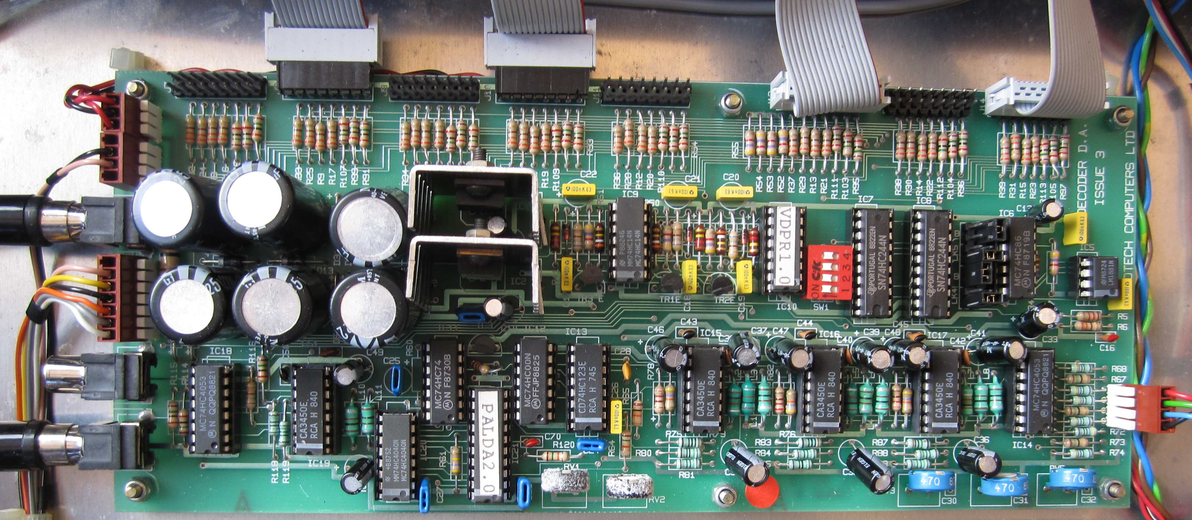
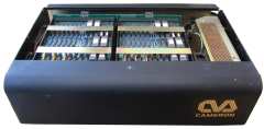
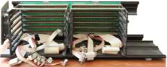
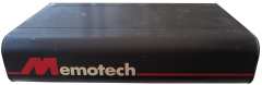
| The Video Wall Controller (DDFS), with
the top cover removed, showing the 2 x 6" card frames for the
controller and frame memory boards. You may be able to make out
the small "Dymo" label on the front upper edge, it is marked "B",
suggesting that this was only a part of a larger system. |
 |
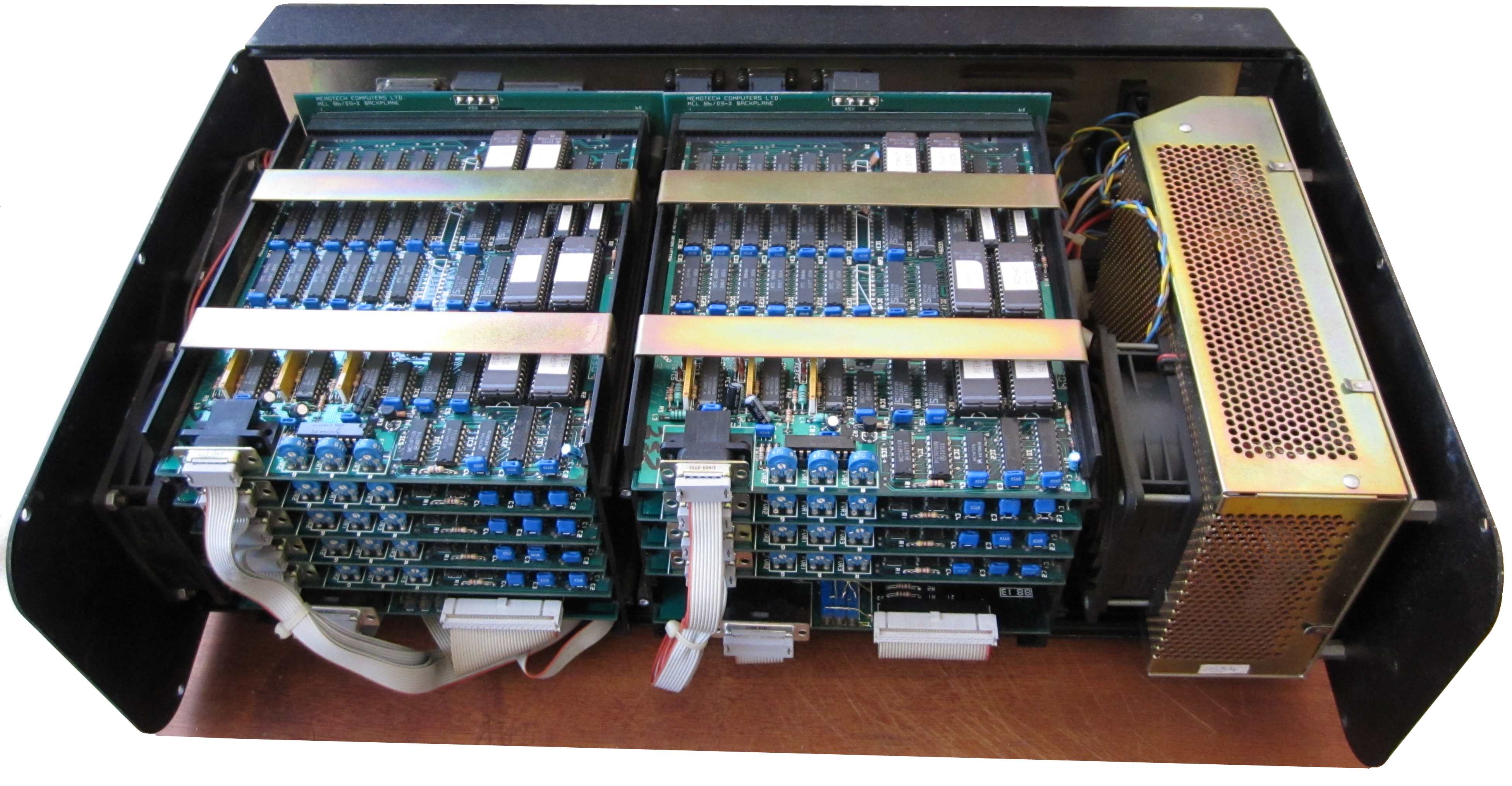
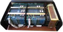
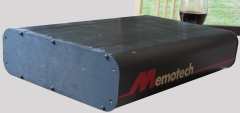
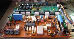
| The front cover removed, exposing the DDFS internals,
the large module at the right hand side is the Astec PSU, mounted on
the right hand side end-plate.
The end-plate has a single 4" air inlet grill and the PSU has a
single fan as shown. The left hand side end plate has a pair of
fans, ensuring good air-flow through the chassis. |
 |
|
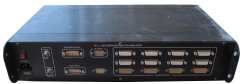
Inside rear view, showing
the connections on the rear panel, from left to right :
-
2x15 way ""D"
connectors for the RGBS inputs from the Video Decoder
-
2 x 34 way IDC
connectors from the MTX Centronics interface
-
12 x 9 way "D"
connector panel (9 used) for the RGBS video outputs
-
The AC power
connection and power switch.
|
 |
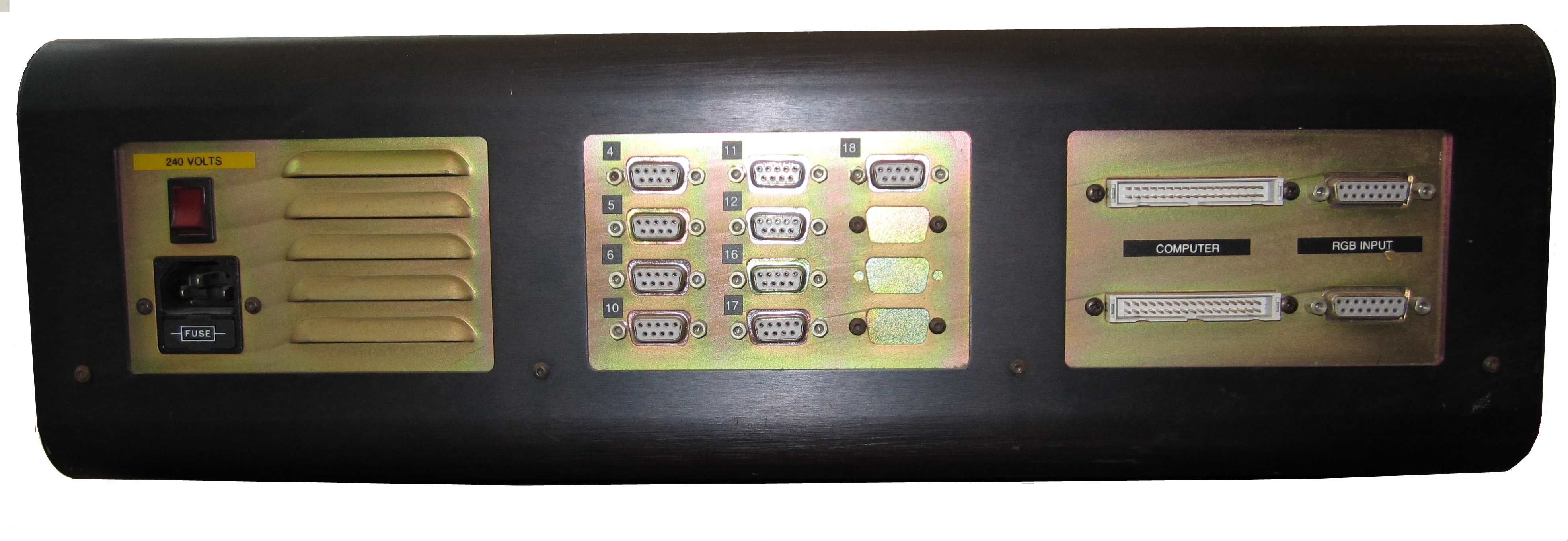
| Outside rear view, showing the connectors described
above. The monitor connections are marked "4", "5", "6", "10,
"11", "12, "16, "17" and "18", again, suggesting that the original
system included another DDFS. |
 |
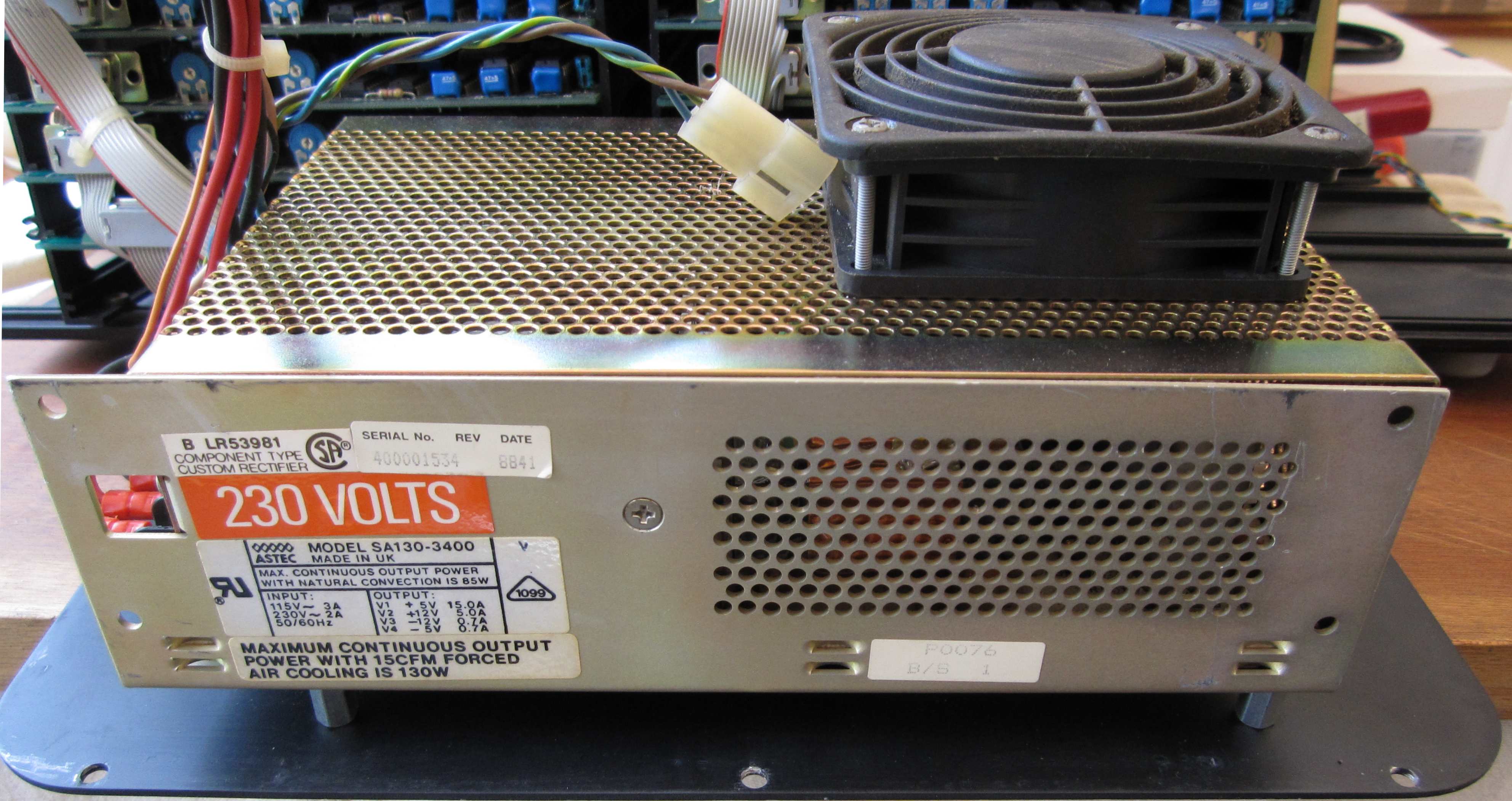
| The DDFS Power Supply - an Astec "SA130-3400", as
the data-plate shows, compared to an FDX, this is a quite "beefy" supply, 15A@5V, 5A@+12V,
0.7A@-5V and 0.7A@-12V and will probably generate quite a bit of heat. The
PSU is shown still mounted on the right hand end-plate, here, you
can see the single fan on the internal side of the PSU. More PSU
photos on this page. |
 |
| Looking into the DDFS with the right
hand end plate and PSU removed |
 |
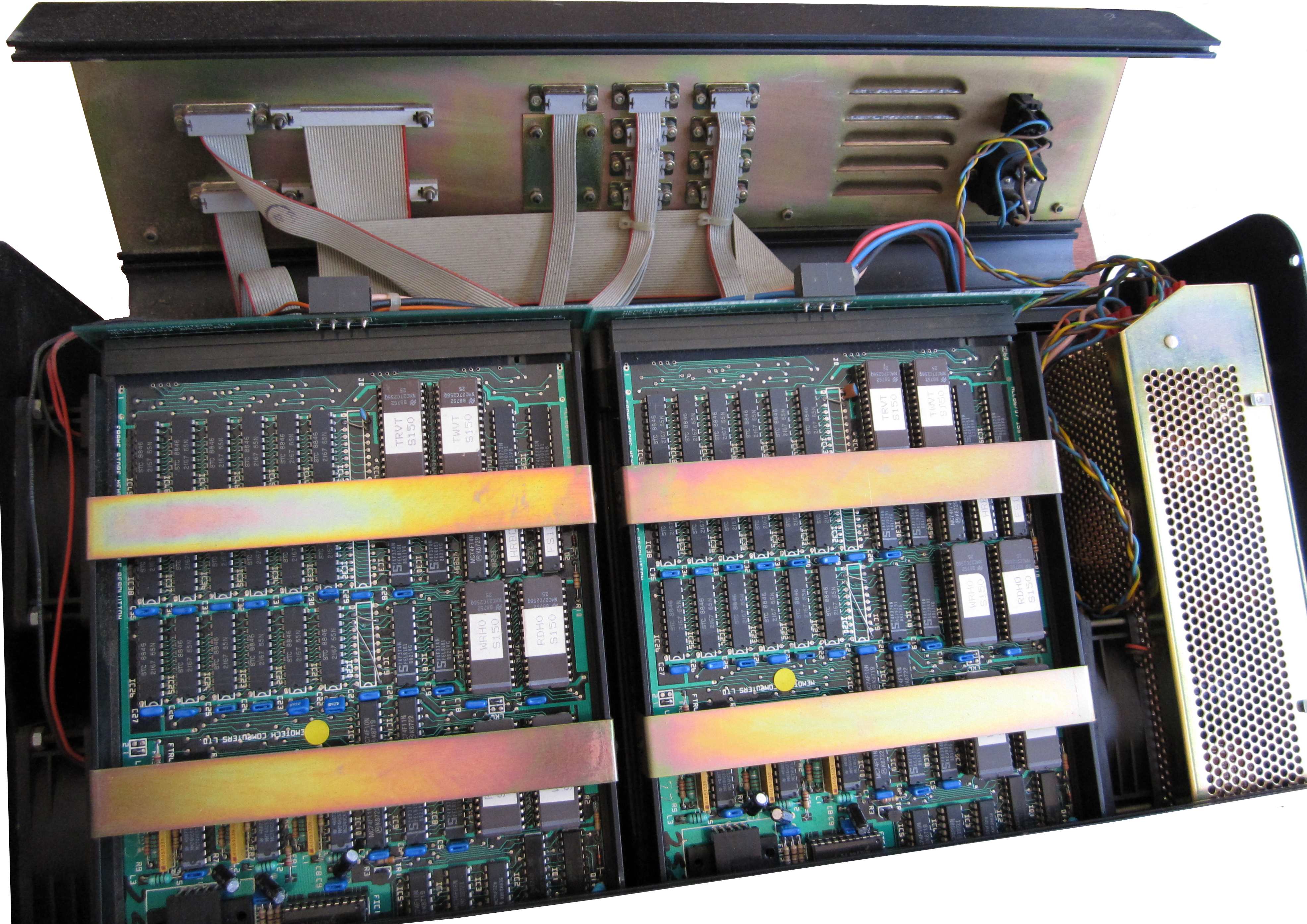
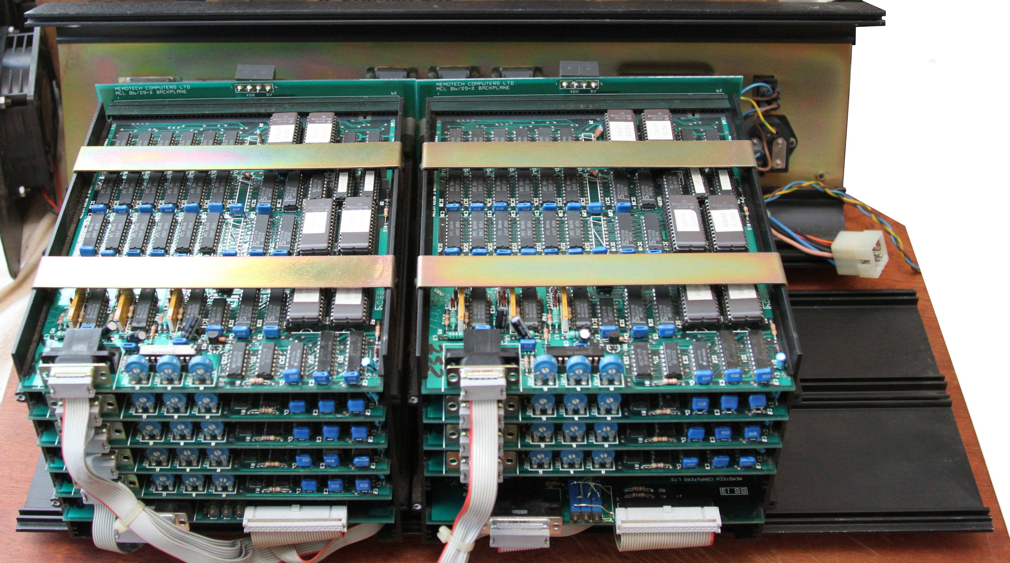
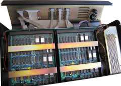
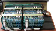
| The end covers and PSU removed, showing the card frames holding
the controller and
frame store memory boards. The two lower boards are the DDFS controller
boards, above them you can see 9 (5+4) frame store boards, each
driving a single monitor, so this DDFS was capable of
driving 9 monitors. The ribbon cables are all connected to the
sockets on the rear of the chassis as shown above. |
 |
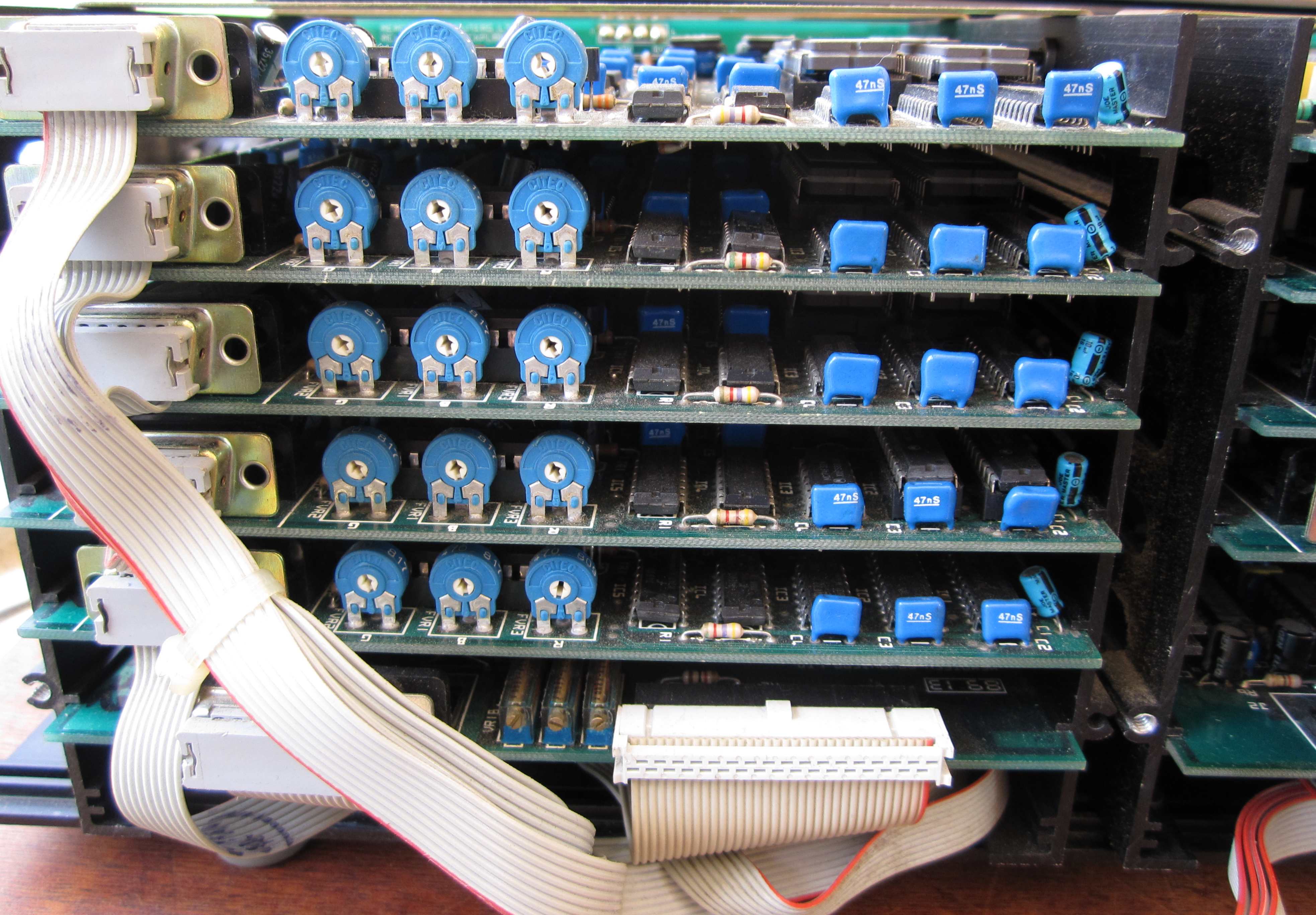
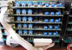
| Close up of the left hand half of the card frame |
 |
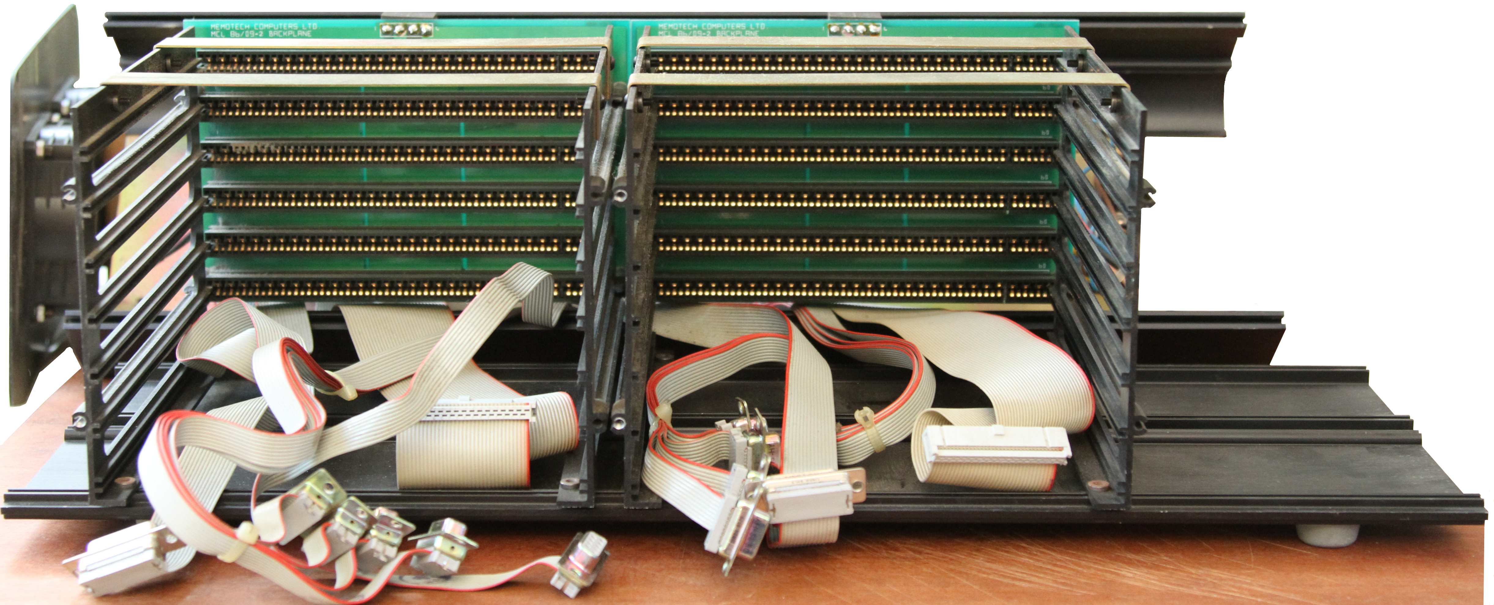
| With the boards removed, the 2 x 6" card frames can
be
seen in more detail - they appear to be the same as the single card
frames used in the FDX. Each card file has a 34-way ribbon cable
for the connection to the MTX computer and a 9-way ribbon cable for
each monitor output. |
 |
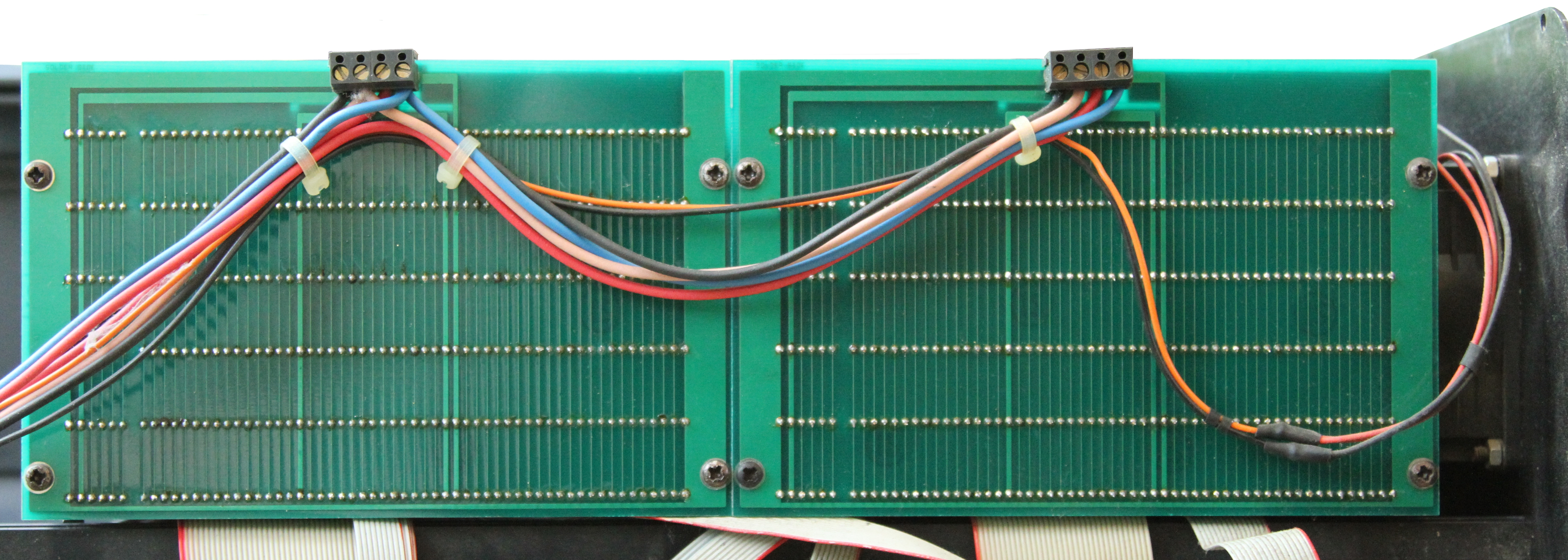
| With the rear cover removed, the back side of the
card cage is exposed, here you can see the power distribution,
including the 12VDC supply for the ventilation fans. |
 |
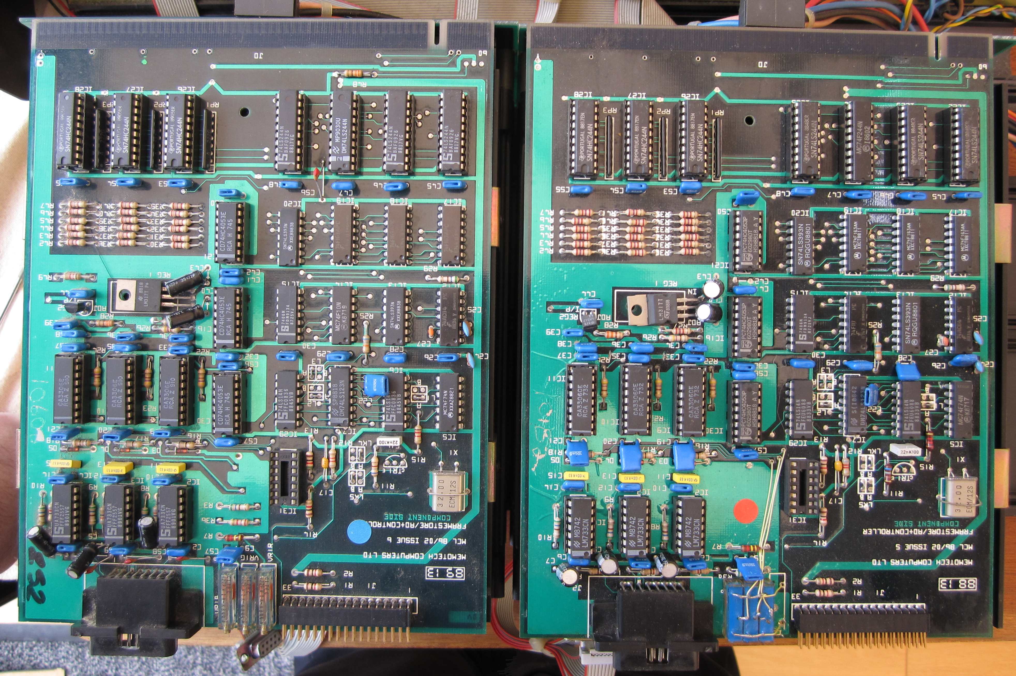
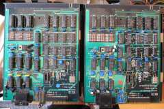
| And just to illustrate that the DDFS controllers were
not immune from the "yellow wire" treatment, here are the two
controllers from my DDFS. You can see that the variable resistors
on the right hand board are of a different type to the ones on the
left and have been modified to suite the board with links and yellow
wires. |
 |
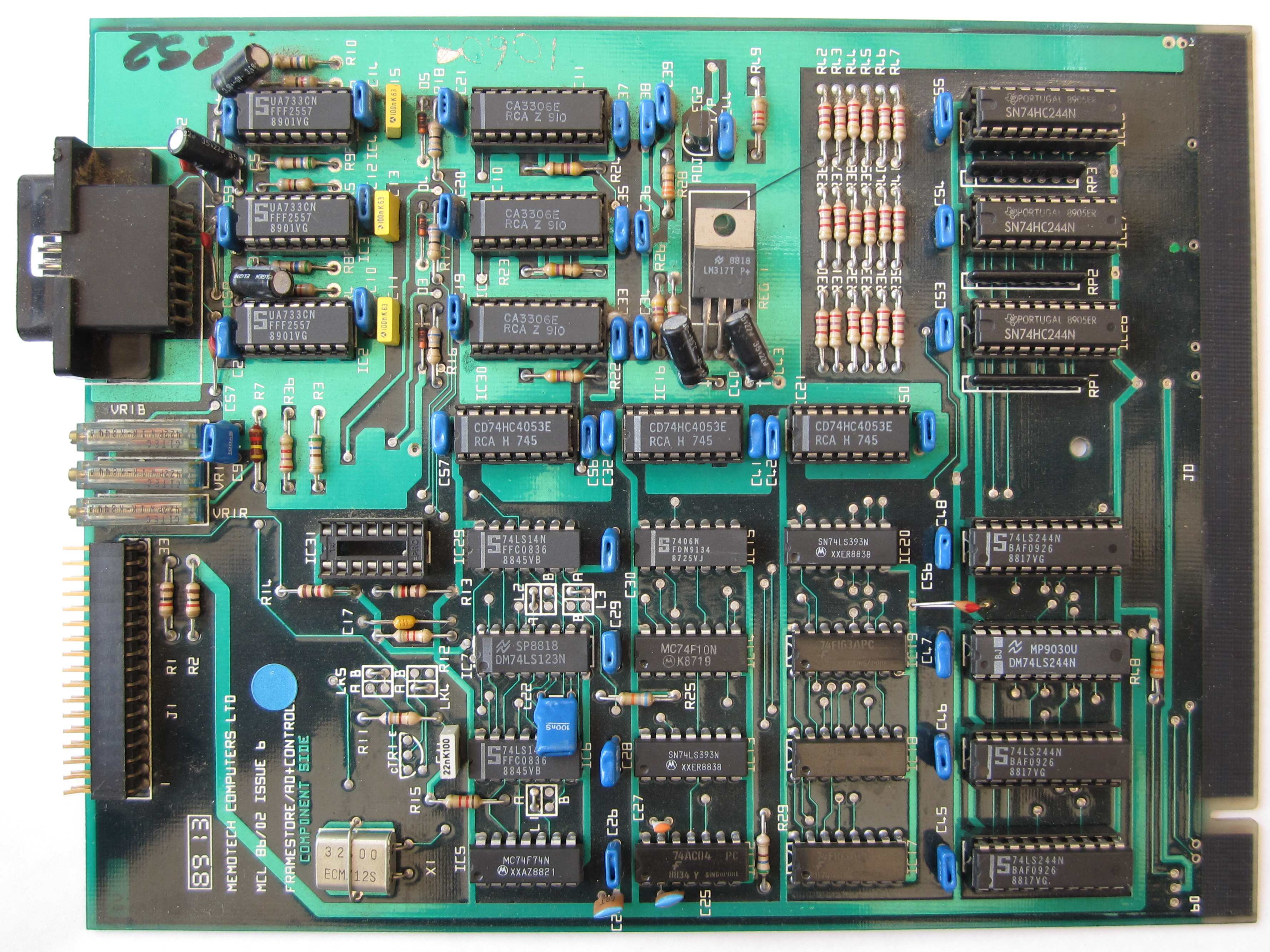
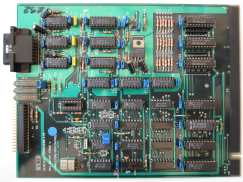
| Close up of the "FramseStore / AD+Controller"
(FSAD) in the
left hand card frame. This is an "86/02 Issue 6 board", with what
appears to be a Date Code of "89 13" |
 |
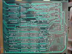
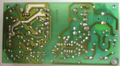
| Solder Side - sans yellow wires! |
 |
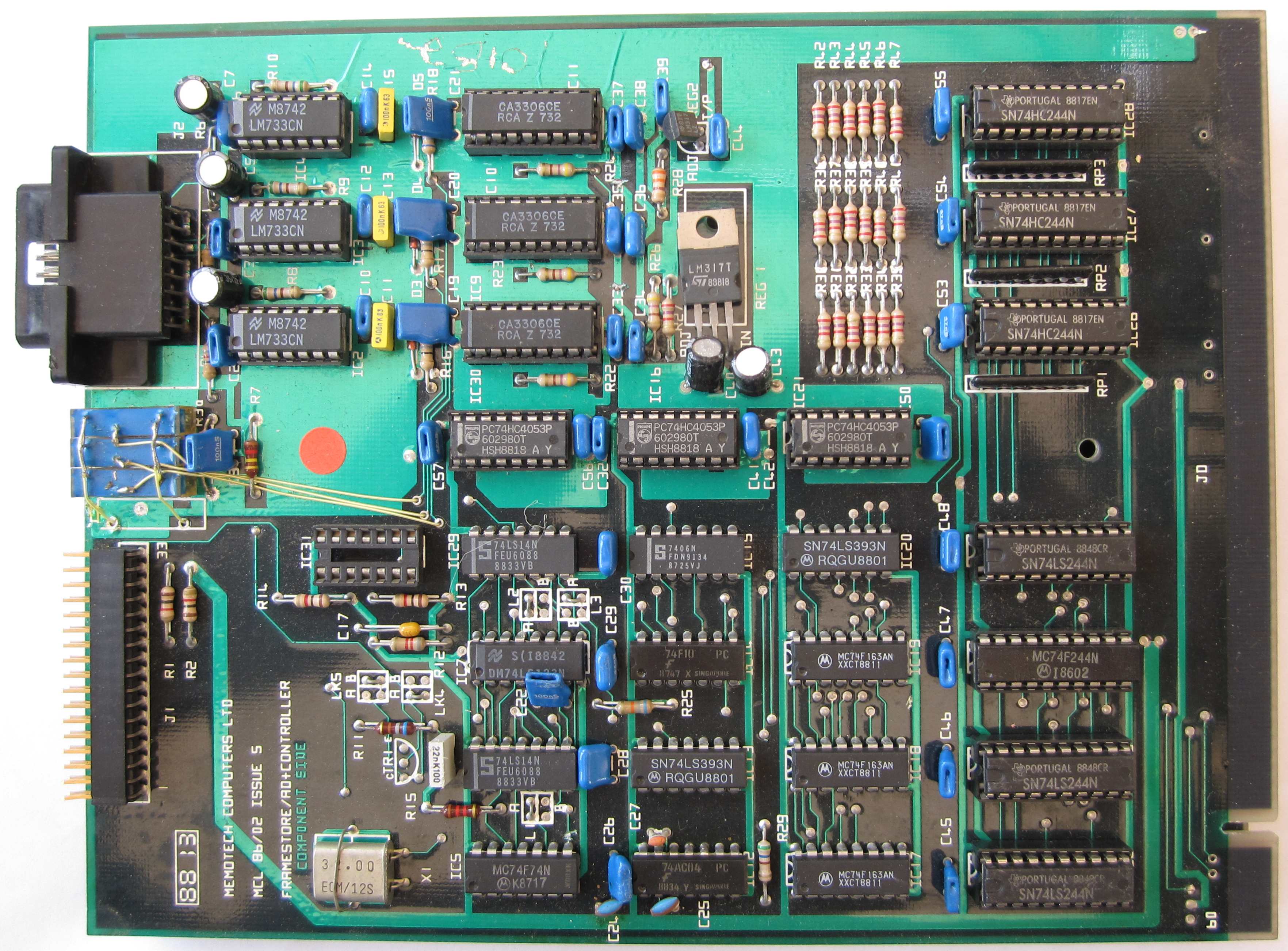
| Close up of the "FramseStore / AD+Controller" in the
right hand card frame. This is an "86/02 Issue 5 board", with what
appears to be a Date Code of "88 13"
|
 |
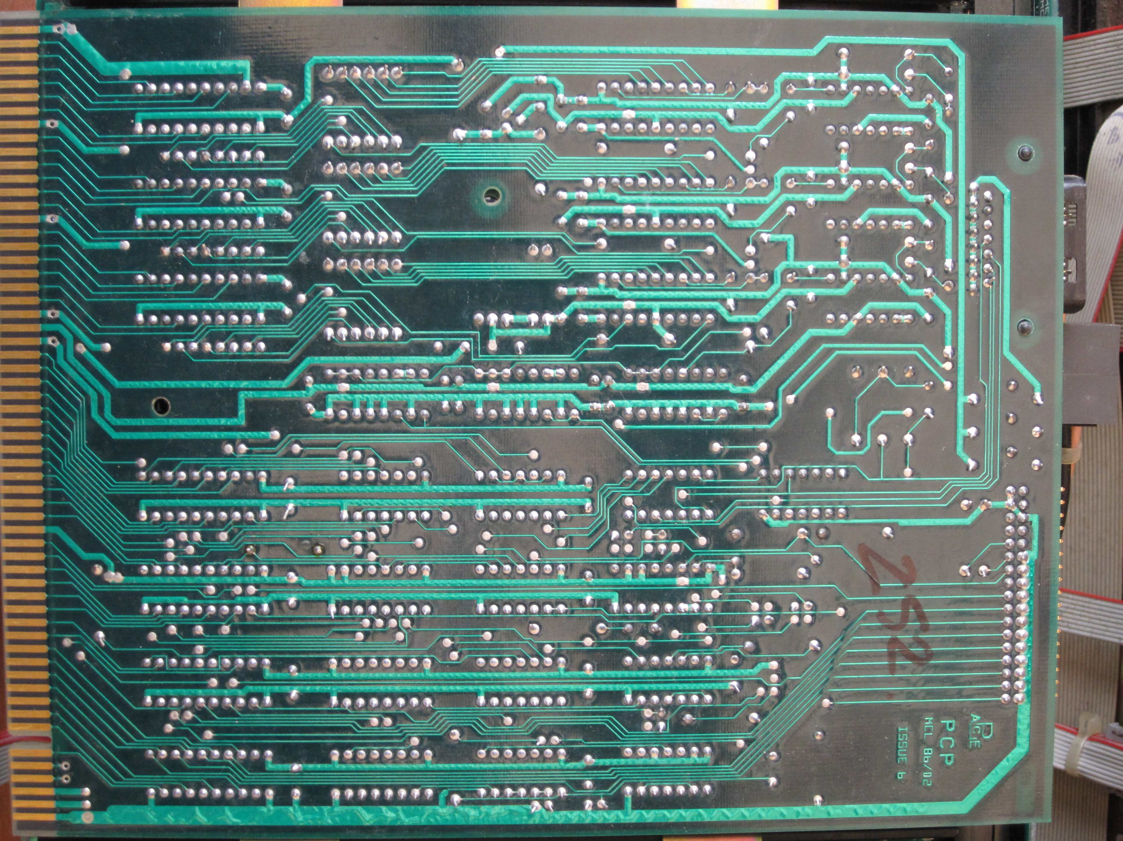
| Solder Side - with a multitude of yellow wires |
 |
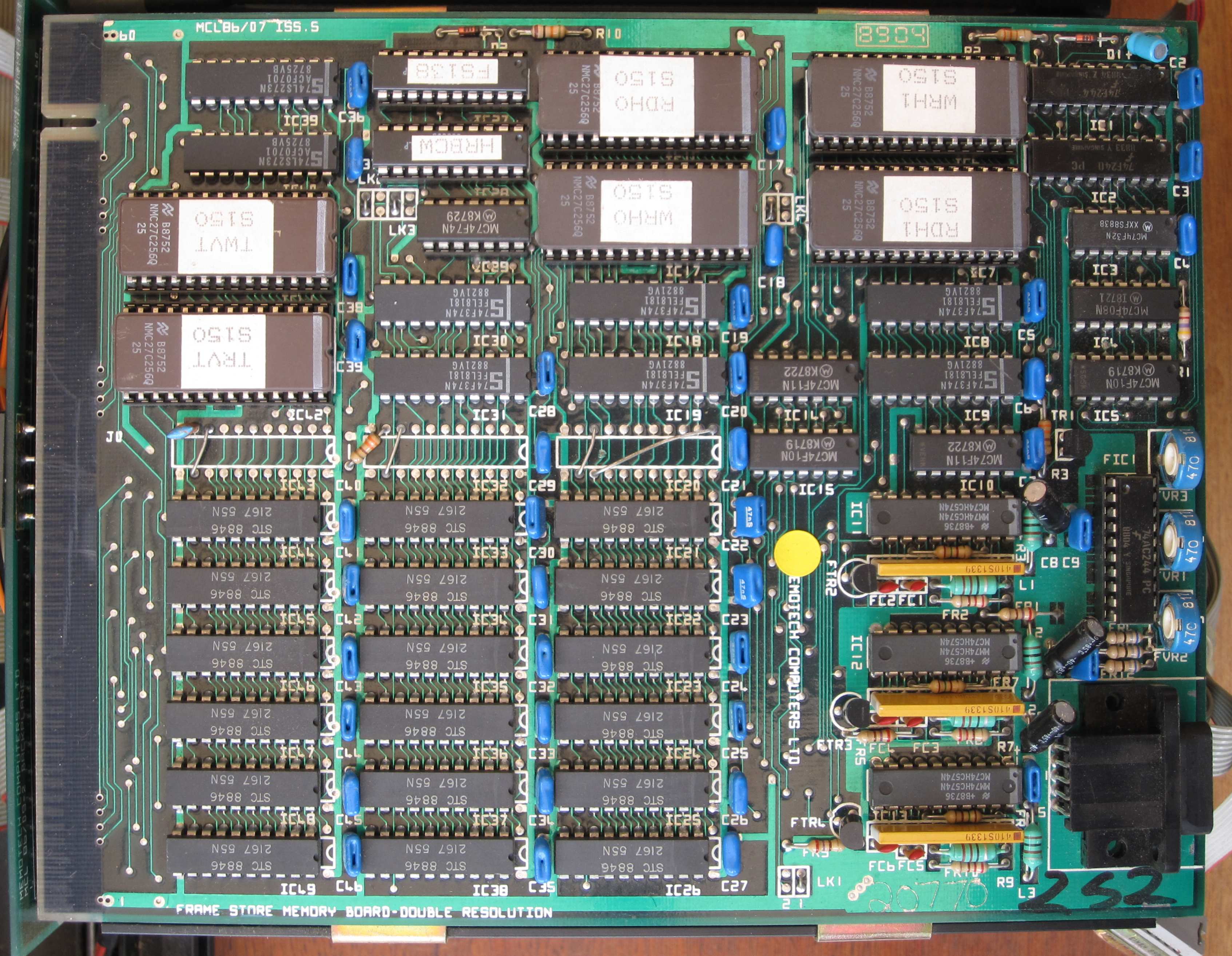
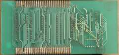
| One of the Frame Store Memory Boards (FSMB) The PCB has the title
"Frame Store Memory Board - Double Resolution" and the ROMs are
marked "S150", similar to the "SR150" part of the serial number.
This is an "86/07 Issue 5 board", with what appears to be a
Date Code of "89 14". Tony Brewer has spotted that this
board uses 20-pin 2167 SRAM chips which are only 16kx1 (128 x 128).
The PCB allows for 22-pin 7187 64kx1 SRAMs (256x256) which are
fitted to the boards in Peter's DDFS.
|
 |
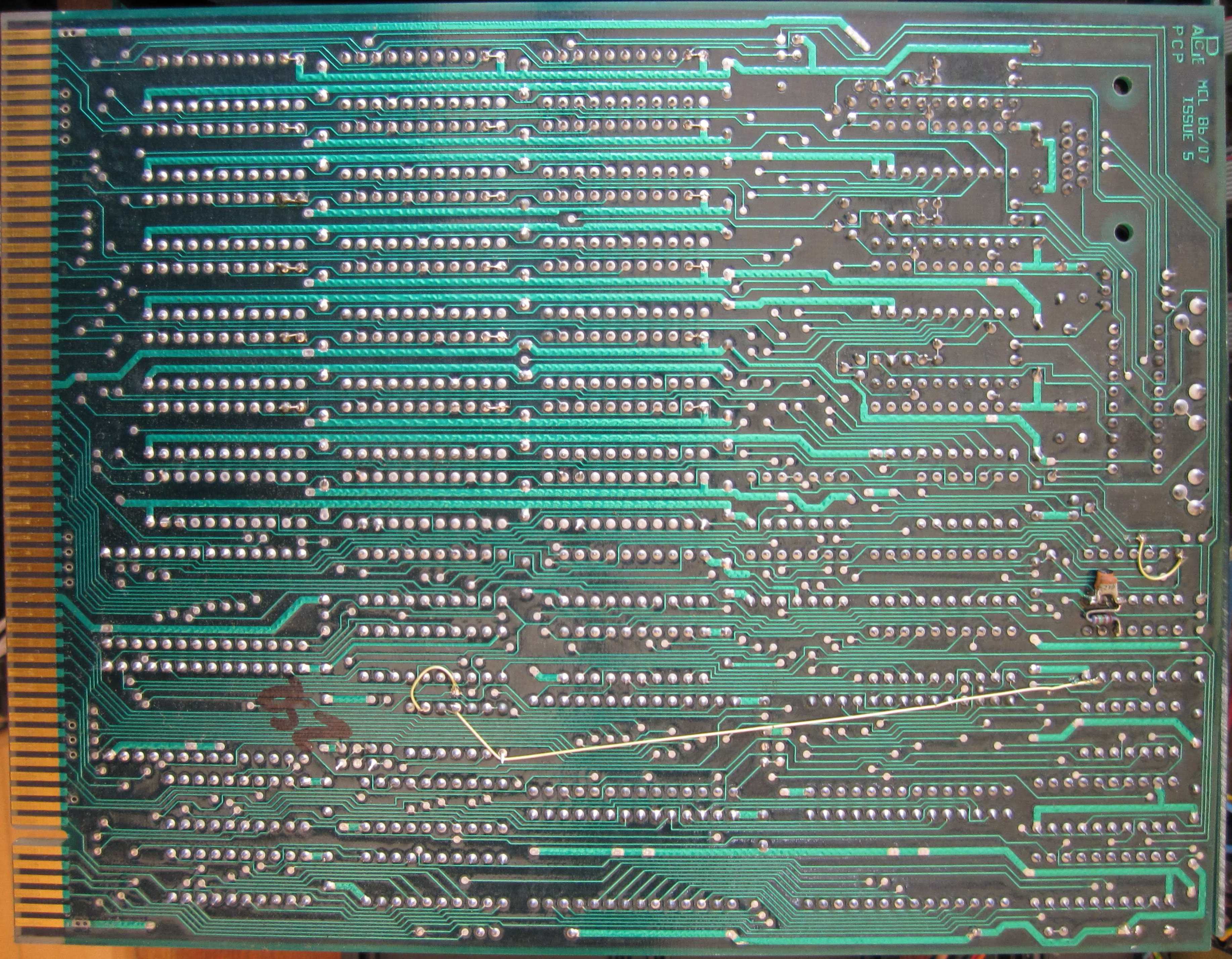
| Tony also notes that the board also allows for 7-bit
video, but only 6 bits are in use. The three sets of 74HC574 + SIL
resistor network + transistor form the major part of cheap but
effective video DACs for red, green and blue. Solder side of the Frame Store Memory Board - with
another yellow wire.
|
 |
The FSMBs are uniquely addressed by configuration
programmed into the PAL in IC27, in my DDFS, the addresses are as
shown :
|
FSMB Address |
| Slot |
Left Side |
Right Side |
| 5 |
FS138 |
FS132 |
| 4 |
FS137 |
FS130 |
| 3 |
FS136 |
FS129 |
| 2 |
FS134 |
FS128 |
| 1 |
FS133 |
(empty) |
| 0 |
(FSAD board) |
(FSAD board) |
|
|
|
Video Decoder & Distribution
Amplifier - 1
(untested) |
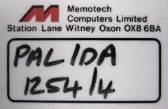
| The Serial Number label from one of the Video Decoders.
Again, not a very interesting photo, other than to suggest that this
is a PAL format Video Decoder and Distribution Amplifier. |
 |
| This module also has a Cameron logo on it,
although it is a completely different design to the one on the DDFS.
It does not actually have the Cameron name on it, but
it is the same logo as is used in the Cameron
Video Wall manual. The
collection of equipment here is a bit of a "mixed bag", some items
are badged Cameron, some Memotech and
some, not at all.
If indeed this was a single system, I wonder if it was bought
piecemeal, perhaps starting with a basic system and then adding to
it later? |
 |
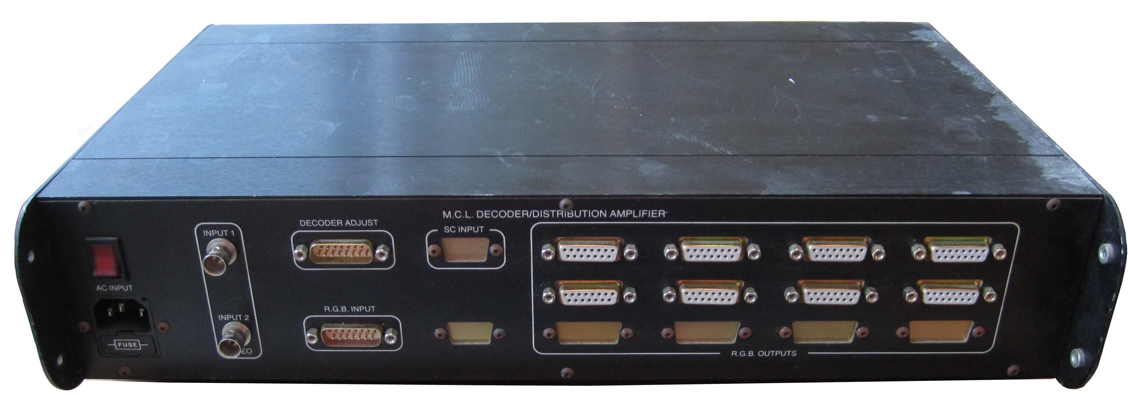
| The front panel of the Video Decoder /
Distribution Amplifier. |
 |
| The rear panel of the Video Decoder /
Distribution Amplifier. This module is slightly different to
Peter's, in that it has more inputs and
outputs, it has two (one) composite video inputs as well as a single
(none) RGB input , it also has eight (four) RGB outputs. |
 |
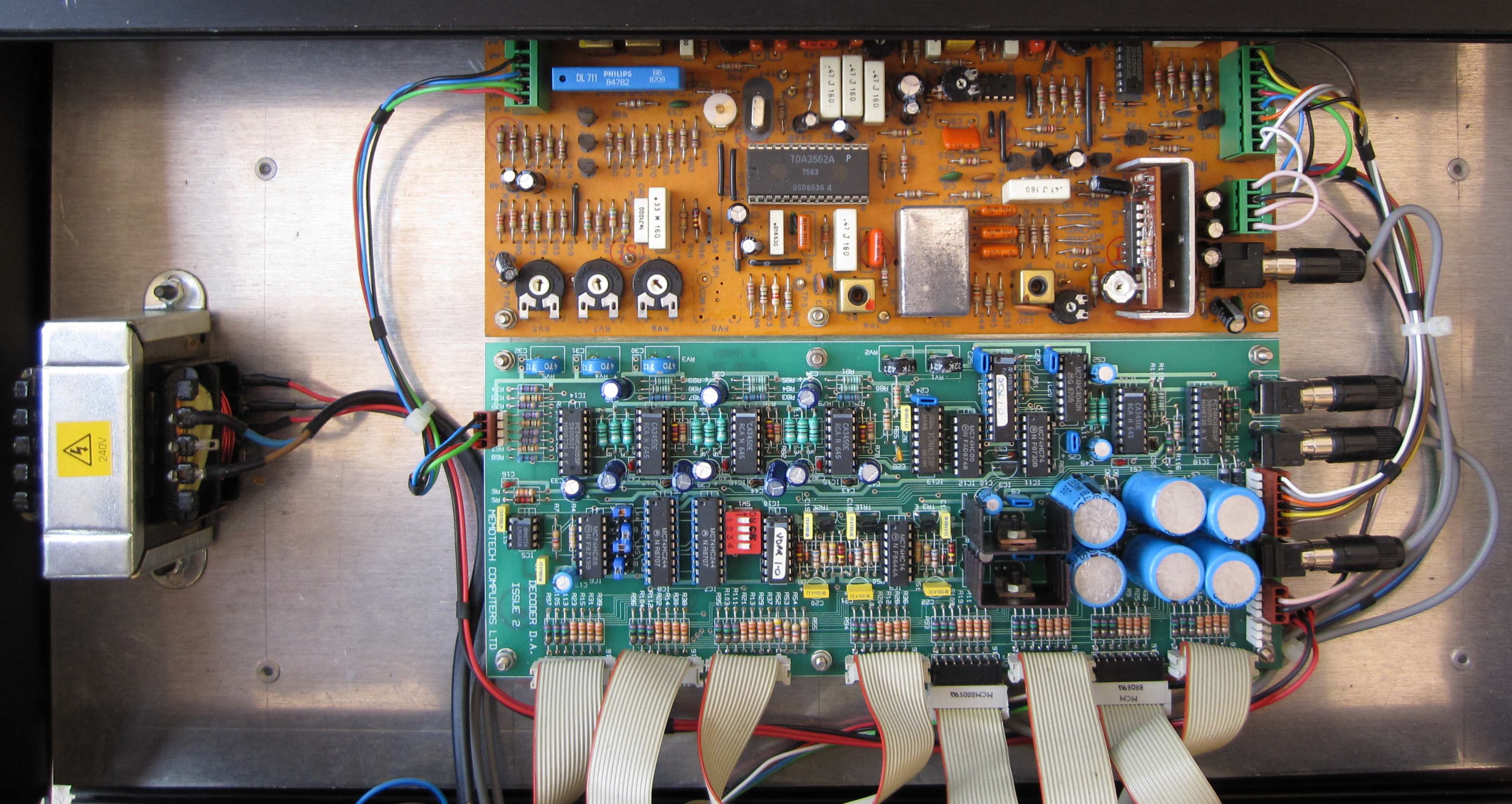
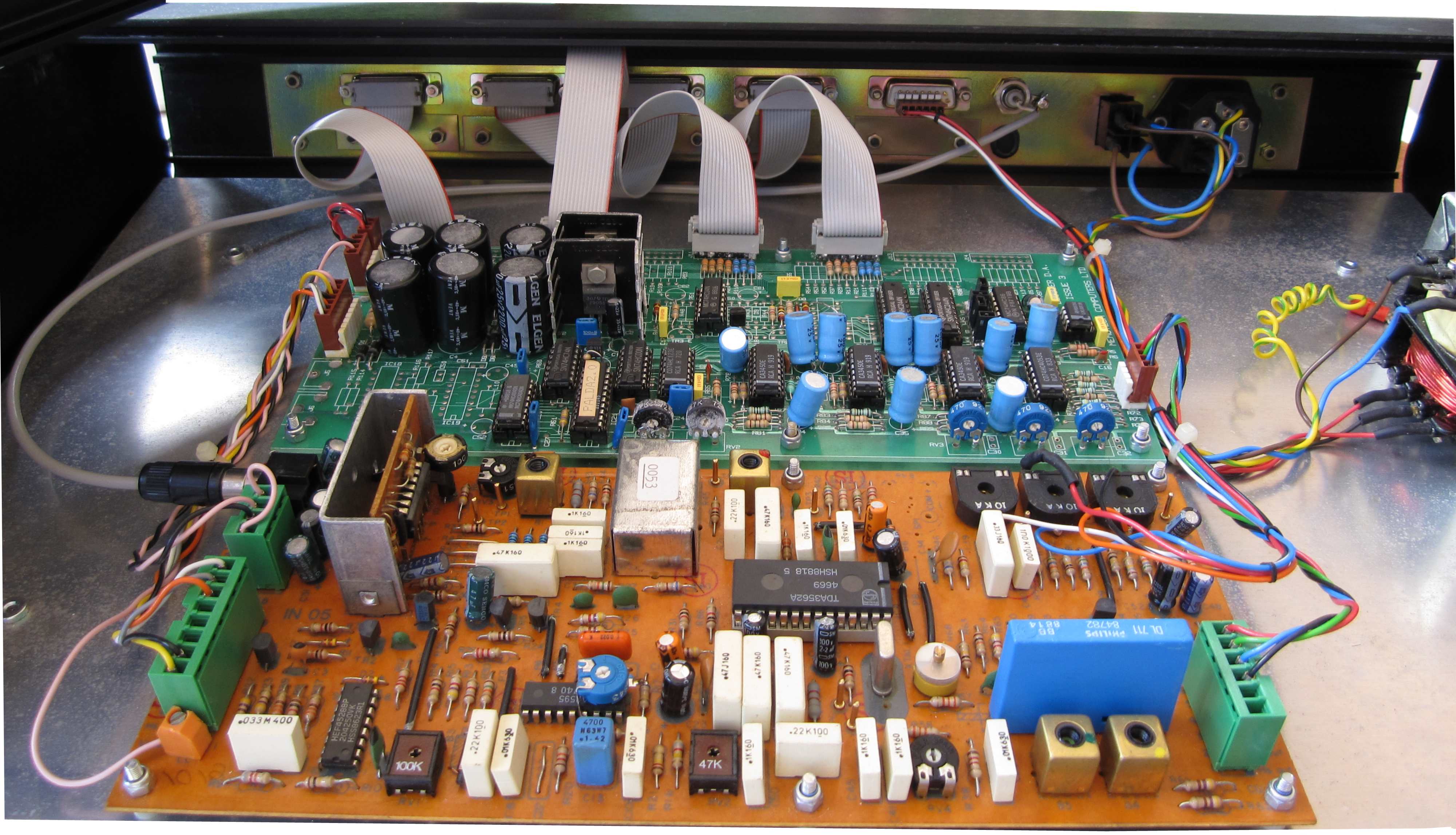
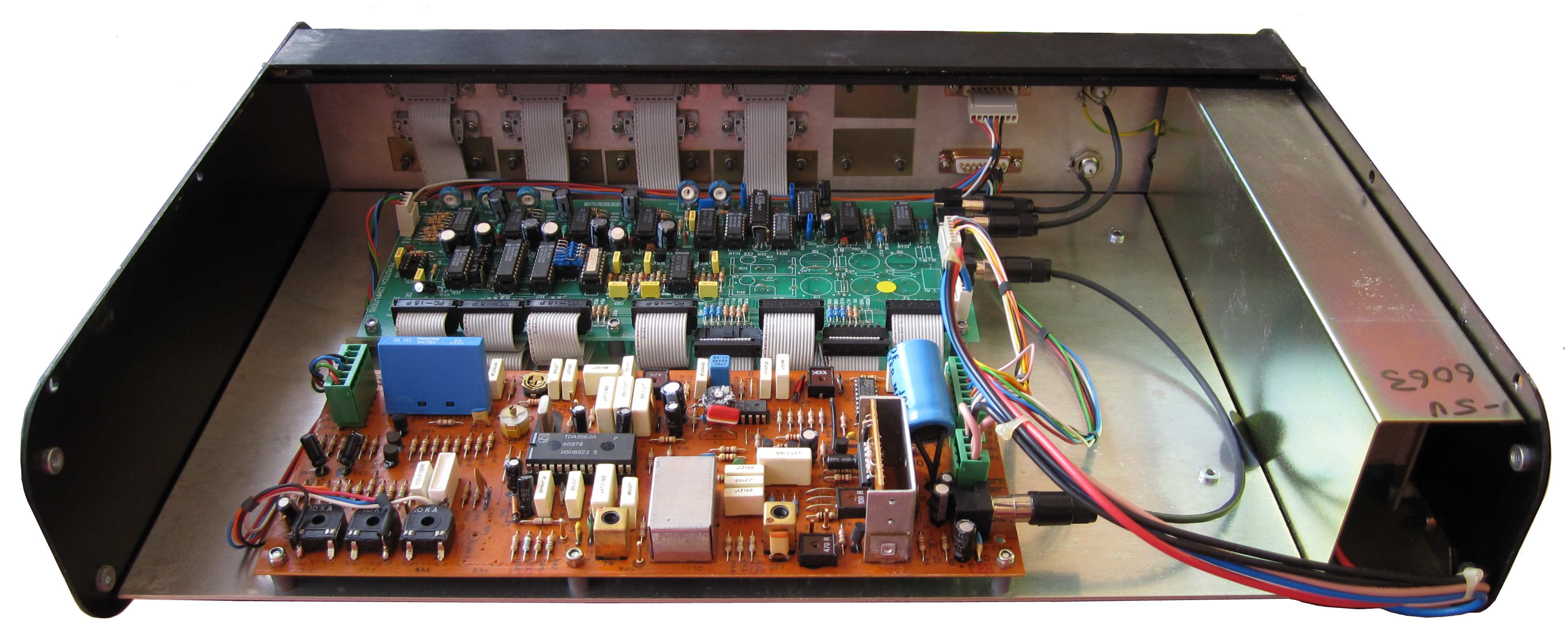
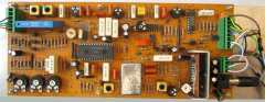
| Internal view of the Video Decoder /
Distribution Amplifier, the Decoder board is
the same as the one in Mike and
Peter's Video Wall (below), but is using
an RGB input from the rear panel the Peter's doesn't.
It has a more complex Distribution Amplifier board
than the more basic version in Peter's, and as noted above, has 2 x
composite video inputs, rather than the single in Peter's. |
 |
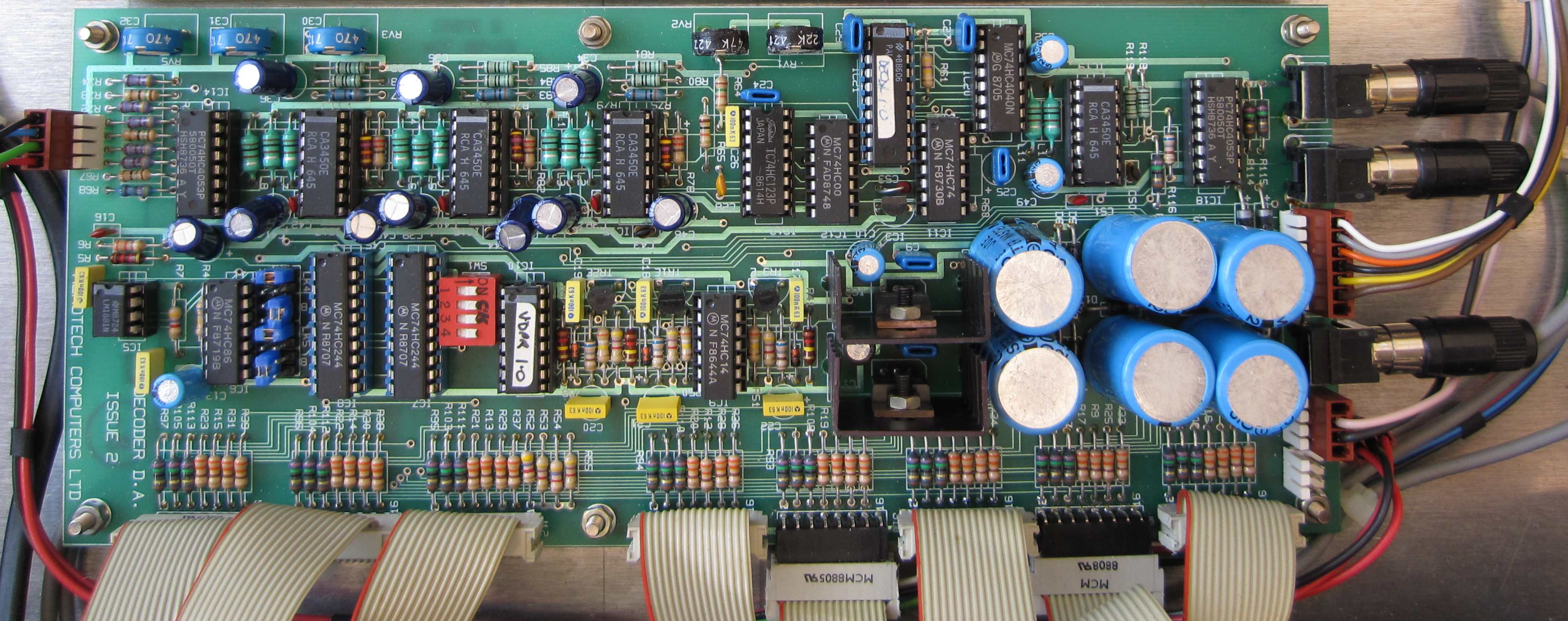
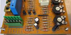
| The lower board is the Distribution Amplifier
(Issue 2).
In my system, the two composite video inputs from the rear panel are
connected to the DA, with one output connection going
to the Video Decoder board, rather than the input
feeding the Decoder directly, as is done in Peter's
system. |
 |
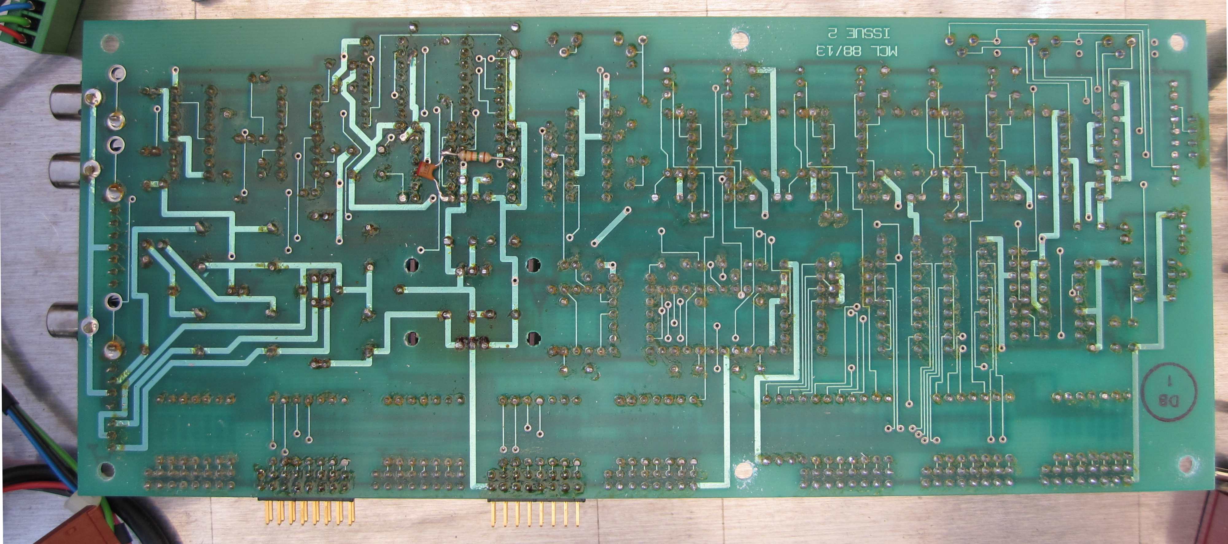
| Solder side of the Distribution Amplifier
board. |
 |
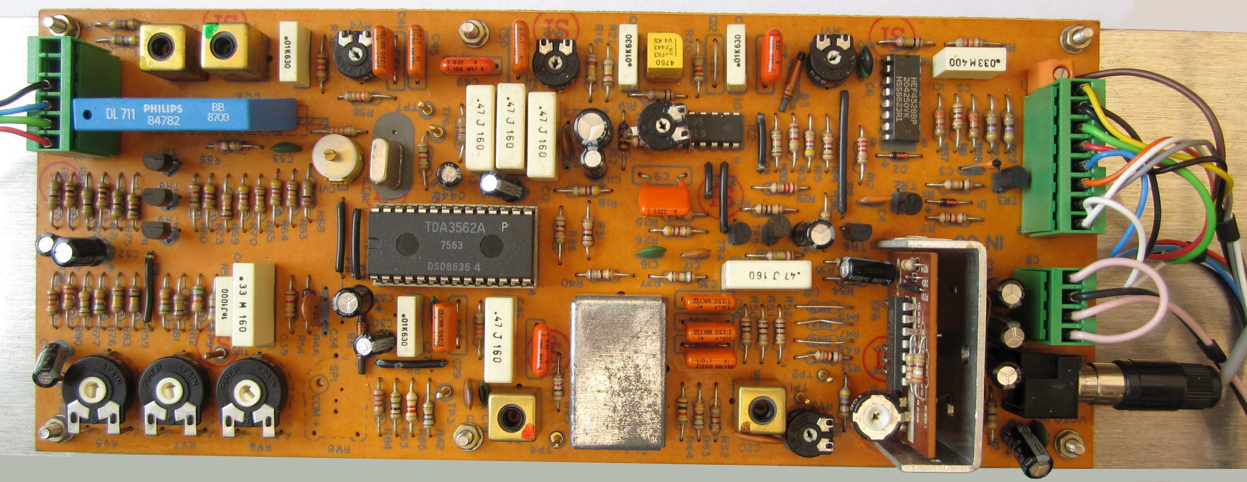
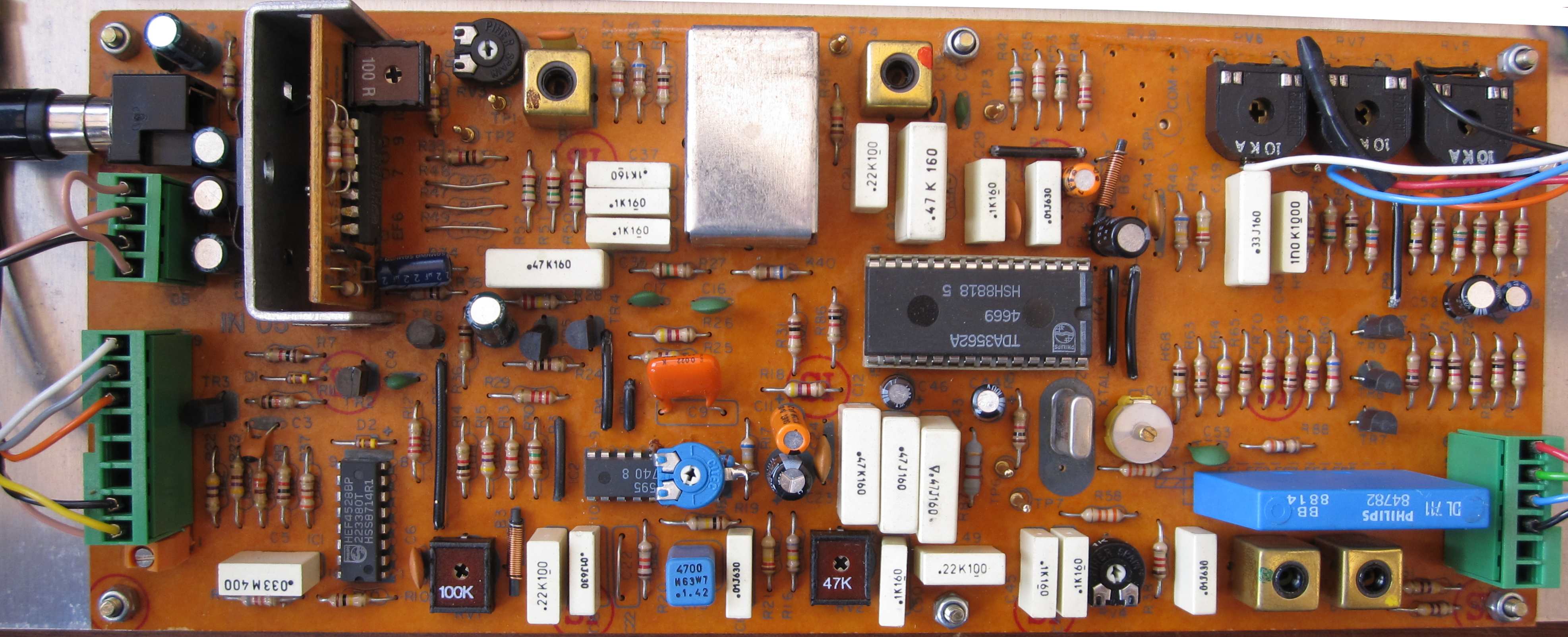
| The upper board is the Decoder, the
main component is a
TDA3562A, "PAL/NTSC One-Chip Decoder." This separates the RGB
signals from the composite video input. This board is also common
to Mike and Peter's Video Walls, although they appear to have been
used in systems with different designs. |
 |
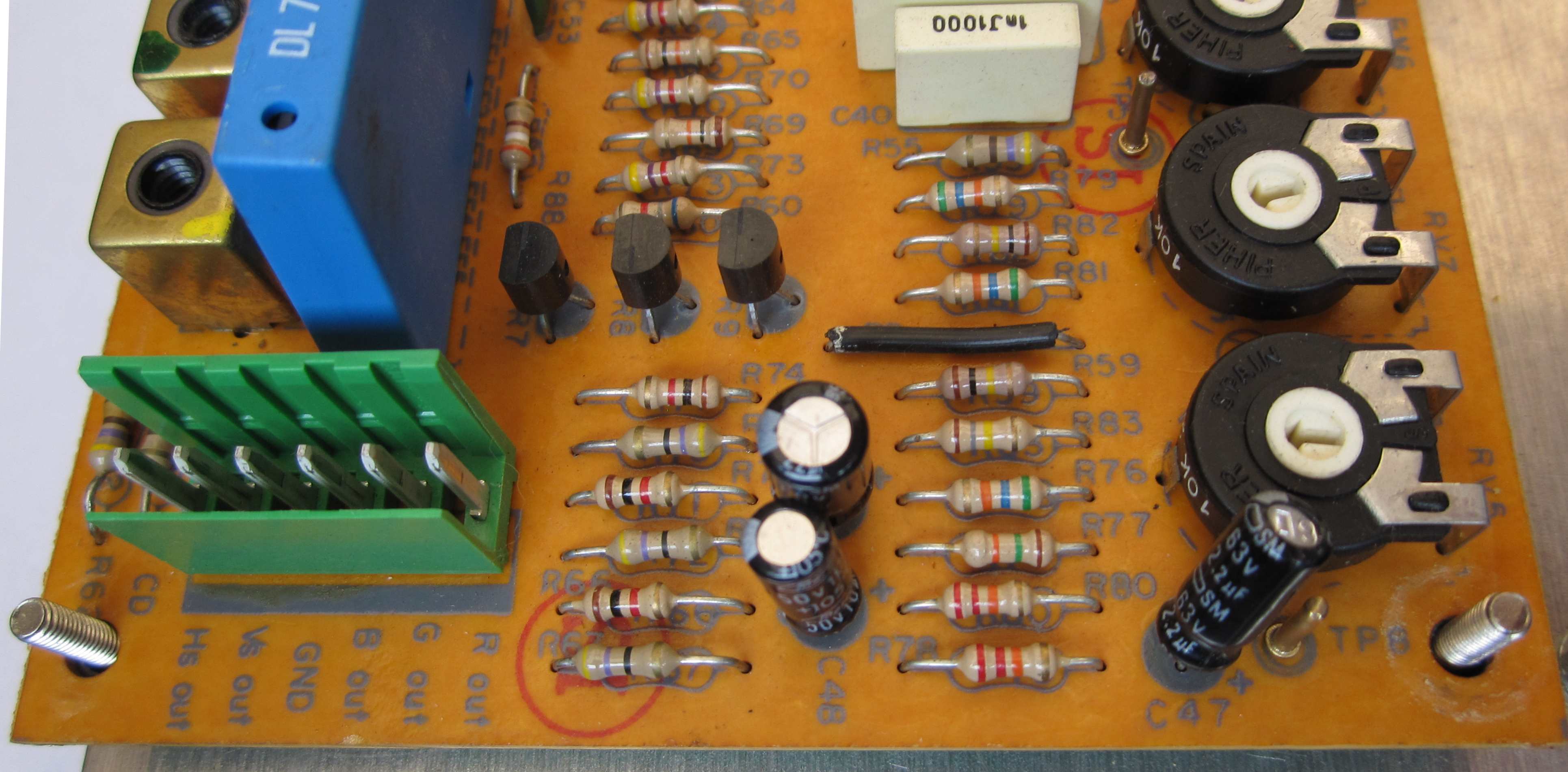
| The Decoder board input connections
from the Distribution Amplifier board, the phono
socket on the right is for the composite video input. The
terminals at the left appear to be taking an RGBS input and
separating the combined sync signal to produce Horizontal (Hs) and
Vertical (Vs) sync signals - only the Hs signal made it onto the
connector - Vs has its own screw terminal. |
 |
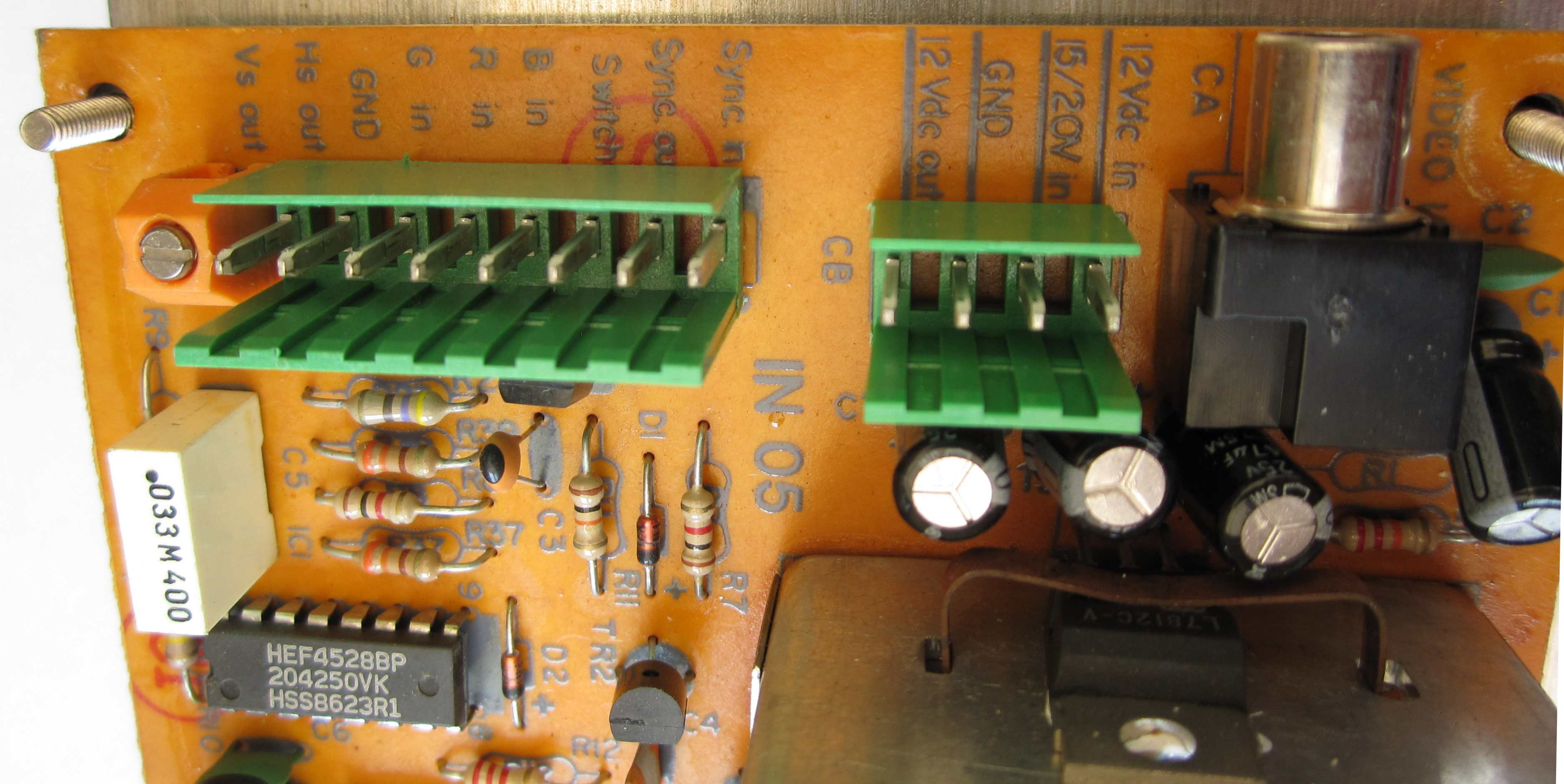
| The Decoder board output connections..
The terminal block feeds RGB and separate sync signals back to
the Distribution Amplifier board in my module. In
Peter's Video Wall, the RGBS Decoder board input is
not used and the RGBS outputs are fed to a much more basic
Distribution Amplifier board. |
 |
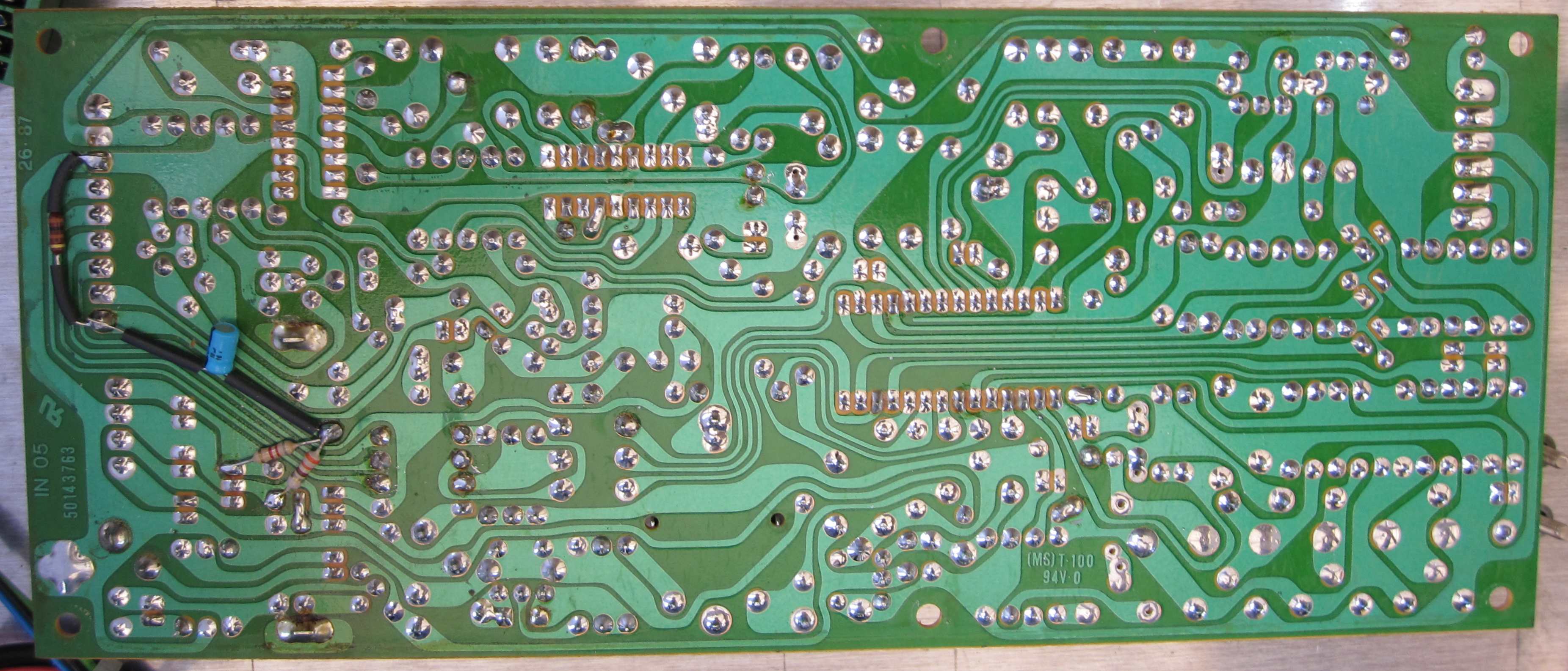
| Solder side of the Decoder board. |
 |
|
Video Decoder & Distribution
Amplifier - 2
(Working) |
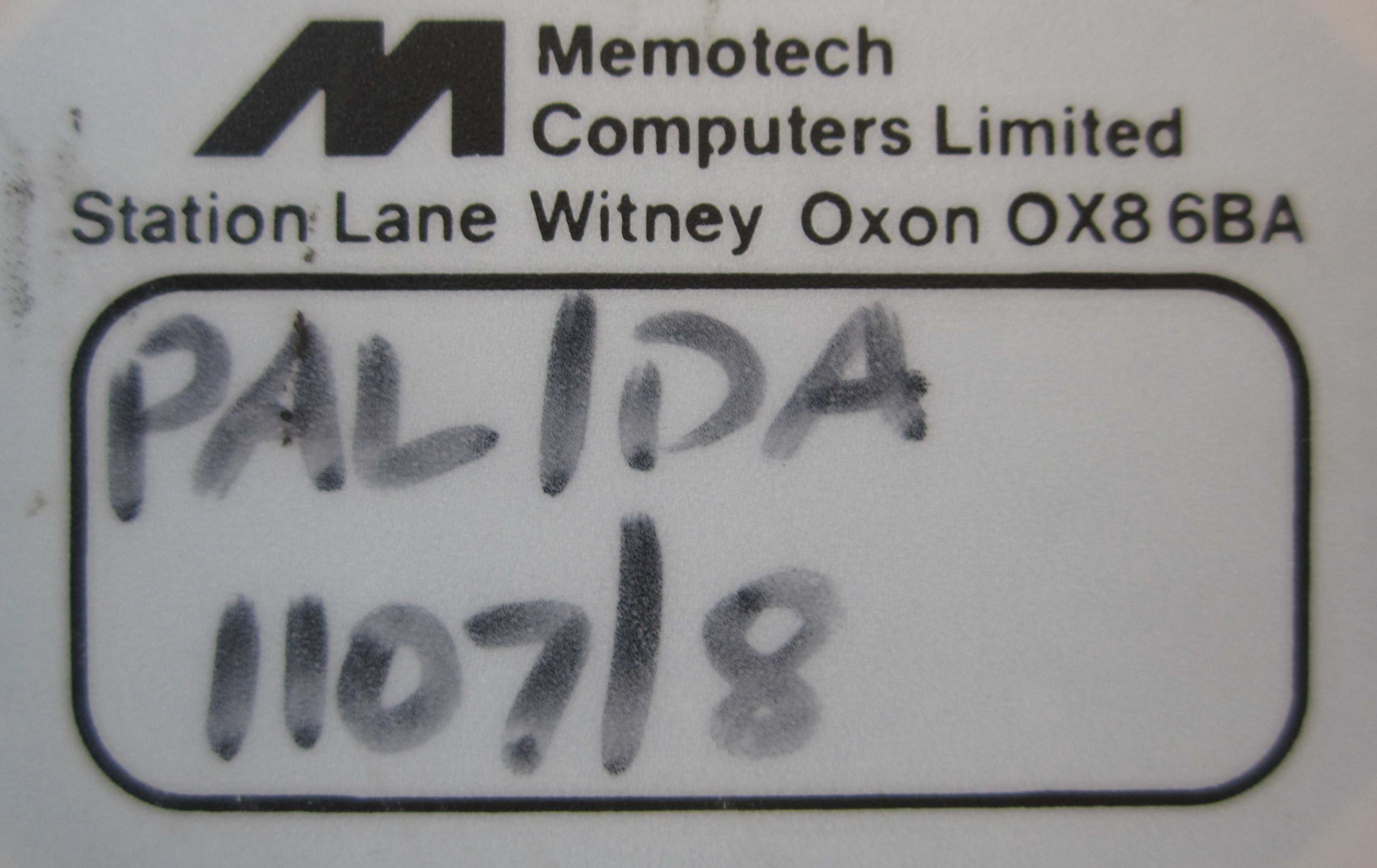
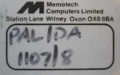
| The Serial Number label from the second Video Decoder
Again, not a very interesting photo, other than to suggest that this
is also a PAL format Video Decoder and Distribution Amplifier.
Given the previous Decoder's configuration (8 outputs)
and serial number (1107/8) though, we can deduce that
the number (/4) after the serial number (1254)
signified that it was a 4-channel output version, like
Peter's. |
 |
| The Cameron logo from this Decoder
module. This logo matches the one on the DDFS,
suggesting that they were supplied by Cameron at the
same time. |
 |
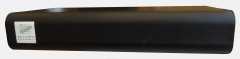
| The front panel of the second Video Decoder /
Distribution Amplifier. |
 |
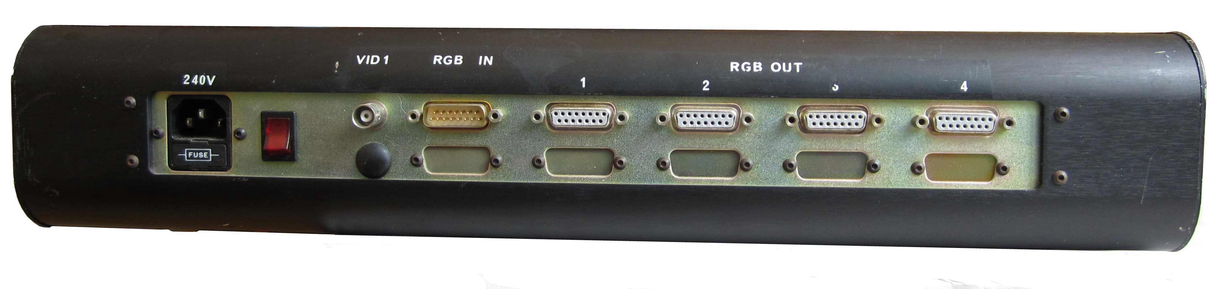
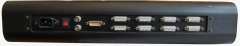
| The rear panel of the second Video Decoder /
Distribution Amplifier. This one is different again, it has
4 RGB outputs like Peter's, and also
what appears to be an RGB input like the the first Decoder,
but with the plug fitted upside down. |
 |
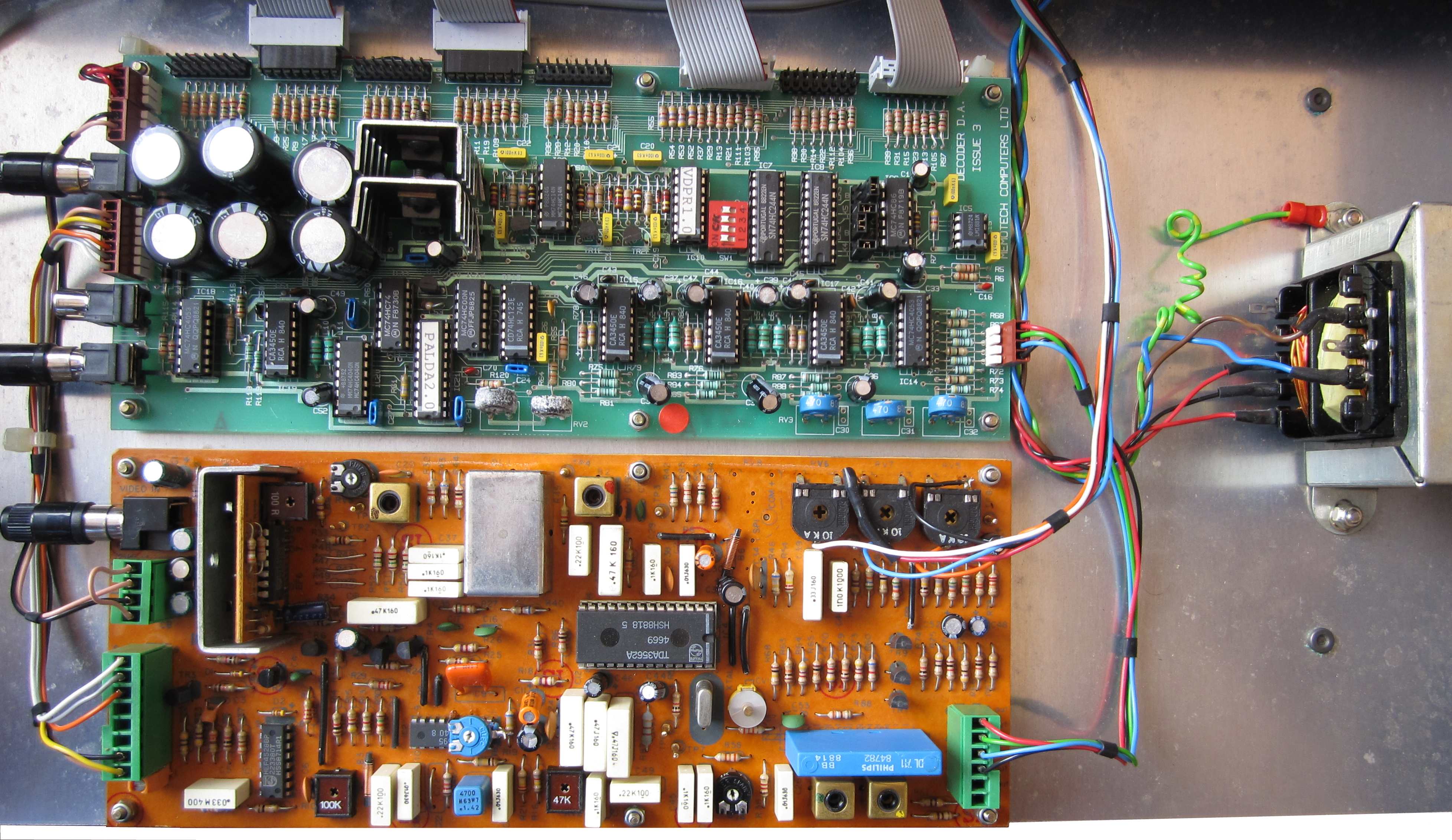
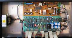
| Internal view of the Video Decoder /
Distribution Amplifier, the Decoder board is
the same as the one in Mike and
Peter's Video Wall (below), and again,
has an RGB input from the rear panel, though it is connected very
strangely!
It has the more complex Distribution Amplifier board,
but only a single composite video input as well as an RGB input. In
another "variation", typical of Memotech hardware, the RGB input has
some "unusual" wiring connecting it to the Decoder
board. |
 |
| In the view above, the upper board is the Distribution Amplifier
(Issue 3).
This time, a single composite video input from the rear panel is
connected to the DA, with the output connection going
to the Video Decoder board. This DA has only 4 RGB
output connections fitted to the rear panel. |
 |
| In this view, the lower board is the Decoder,
again, the
main component is a
TDA3562A. As mentioned above, the RGB input connection from
the rear panel is very odd - it is connected to 10K variable
resistors visible in the upper right hand corner. |
 |
|
Video Decoder & Distribution
Amplifier - 3
(untested) |
|
The Serial Number label
from the third Video Decoder
We know to expect a PAL format Video Decoder and Distribution Amplifier.
Knowing what we do about the Decoder serial numbers,
we could deduce that it will be a 4-channel output version - so,
just like one of the ones above?
-
Almost, but this is Memotech hardware! - so it has got to be
different . . . . |
 |
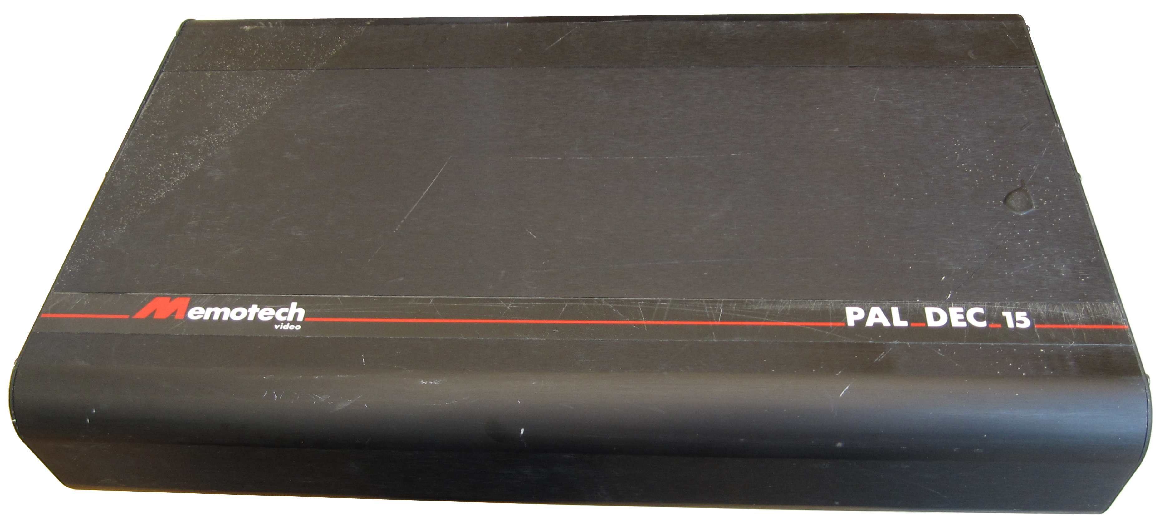
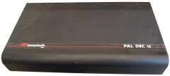
| The front panel of the third Video Decoder /
Distribution Amplifier. This one has the highest serial
number so far, has a "Memotech Video" label and what looks to
be a product name of "PAL DEC 15". Any suggestions for
what DEC might have been an acronym for? |
 |
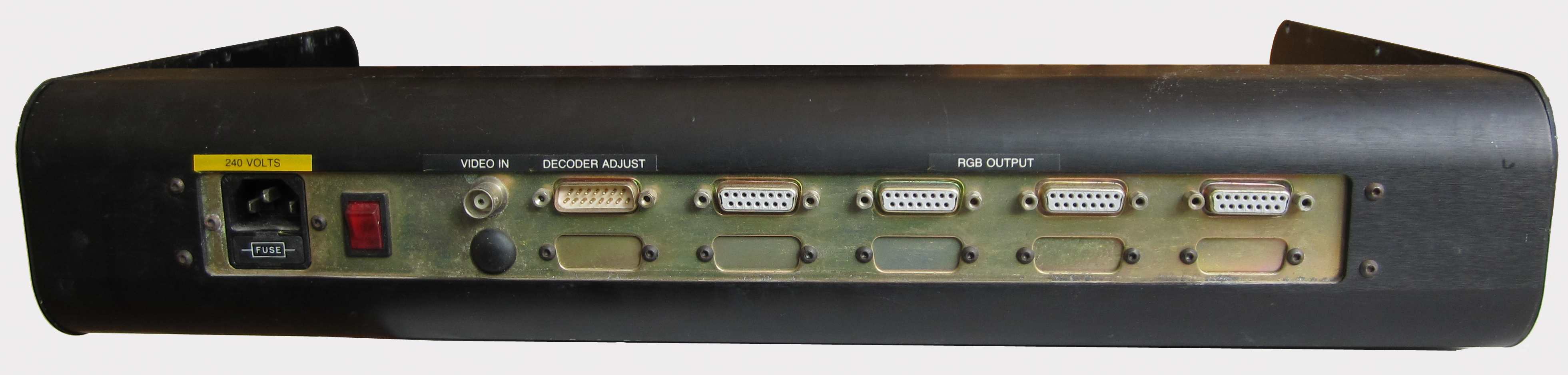
| The rear panel of the third Video Decoder /
Distribution Amplifier (with the cover removed). This time,
the apparently upside down RGB input connection is labelled "Decoder
Adjust", that makes more sense than it being an RGB input. |
 |
| View of the rear panel of the third Decoder
from the inside |
 |
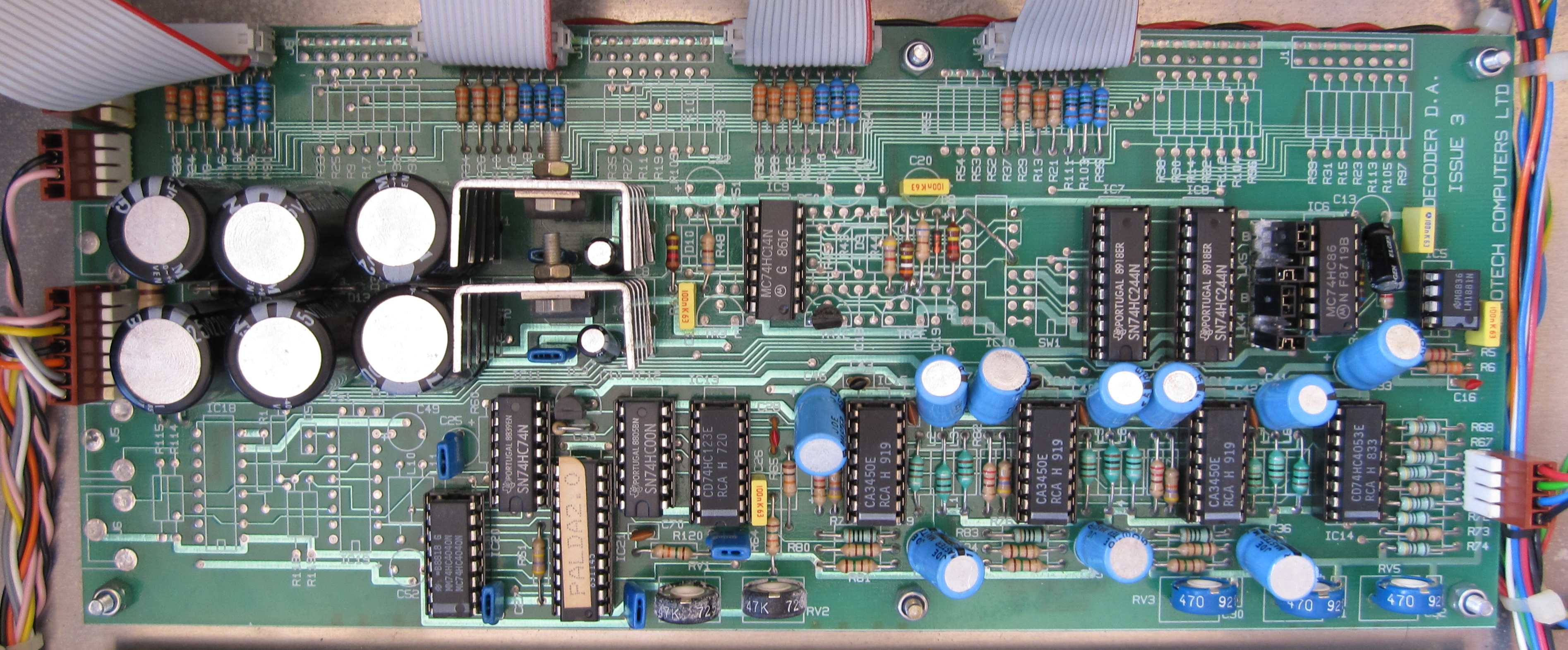
| Internal view of the Video Decoder /
Distribution Amplifier. The Decoder board is
the same as the others, this time, the single Video In connection
from the rear panel is connected directly to it. It has the more complex Distribution Amplifier board
, but this board does not have any external inputs and just takes in
the RGB output from the Decoder board. |
 |
| In the view above, the upper board is the Distribution Amplifier
(Issue 3).
This time, the DA board does not receive any external
video inputs and the Phono input, as well as the unused RGB outputs,
do not even have connectors fitted to the board. |
 |
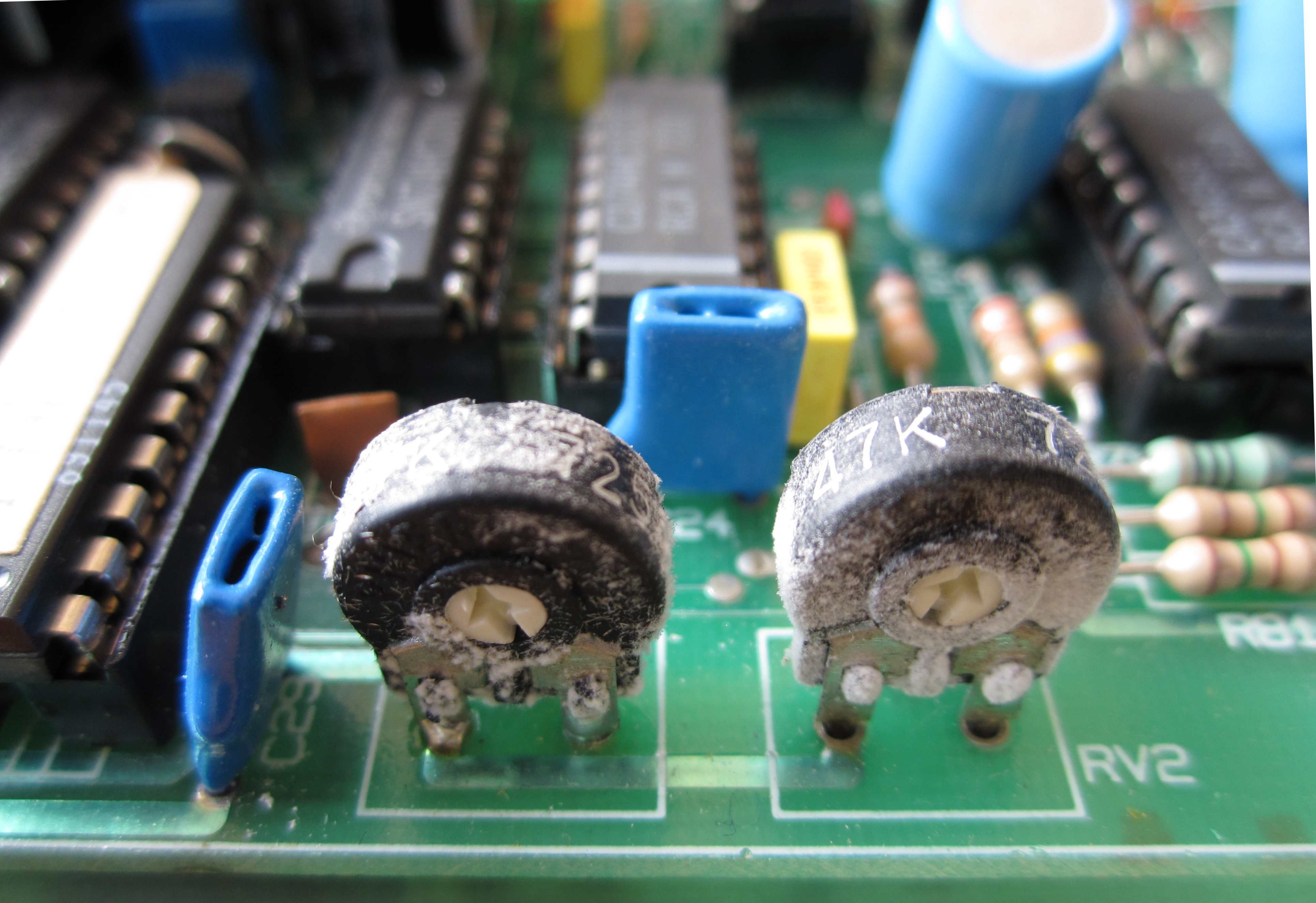
| Like the second , this board has some very odd
corrosion type deposits on RV1 and RV2, whereas RV3, RV4 and RV5 are
unaffected.
I have no idea what may have caused this, overheating perhaps? -
if you know what causes this type of deposit, please let me know. |
 |
| In this view, the lower board is the Decoder,
again, the
main component is a
TDA3562A. With the "Decoder Adjust" label on the
rear panel, the wires from the 15-way "D" connector to the variable
resistors on the board now makes more sense. |
 |
|
Video Decoder & Distribution
Amplifier - 4
(Seen enough yet? - I don't know why there are so
many of the Decoder Modules - any ideas?)
(Working) |
|
The Serial Number label
from the fourth Video Decoder
We know to expect a PAL format Video Decoder and Distribution Amplifier.
This one has a much later
serial number and no "/x" after the number, it is an
8-channel output module though - perhaps this had now become a
Memotech "standard" product - if ever they had such a thing ! |
 |
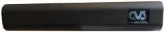
| The front panel of the fourth Video Decoder /
Distribution Amplifier. This one has the highest serial
number and has a "Memotech" label in a very
prominent position on the front of the unit. Perhaps this is the
livery that Memotech used when they started marketing the Video Wall
under their own name - rather than an agent - such as Cameron? |
 |
| Close up of the "Memotech" logo |
 |
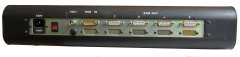
| The rear panel of the fourth Video Decoder /
Distribution Amplifier. This time,
there is a 15-way "D" connector for "Decoder
Adjust", as well as an additional connection marked as
"RGB Input". The unit has 8 populated RGB output
connectors, panel space for 4 more and 2 BNC Video inputs. |
 |
| Unlike the rest of my Video Wall equipment, this
Decoder, and the module below, are both about 2" narrower
than the free standing units, and have tapped holes in the sides to
facilitate mounting in a rack of some description. |
 |
| View of the rear panel of the fourth Decoder
from the inside You can see that the basic transformer used on the
previous versions has been removed, a "proper" power supply is
installed in the square steel tube on the right hand side. |
 |
| Internal view of the Video Decoder /
Distribution Amplifier. The is orientated differently from
the previous examples, making for neater installation of the RGB
output ribbon cables - they now pass under the board for connection
to the rear panel. |
 |
|
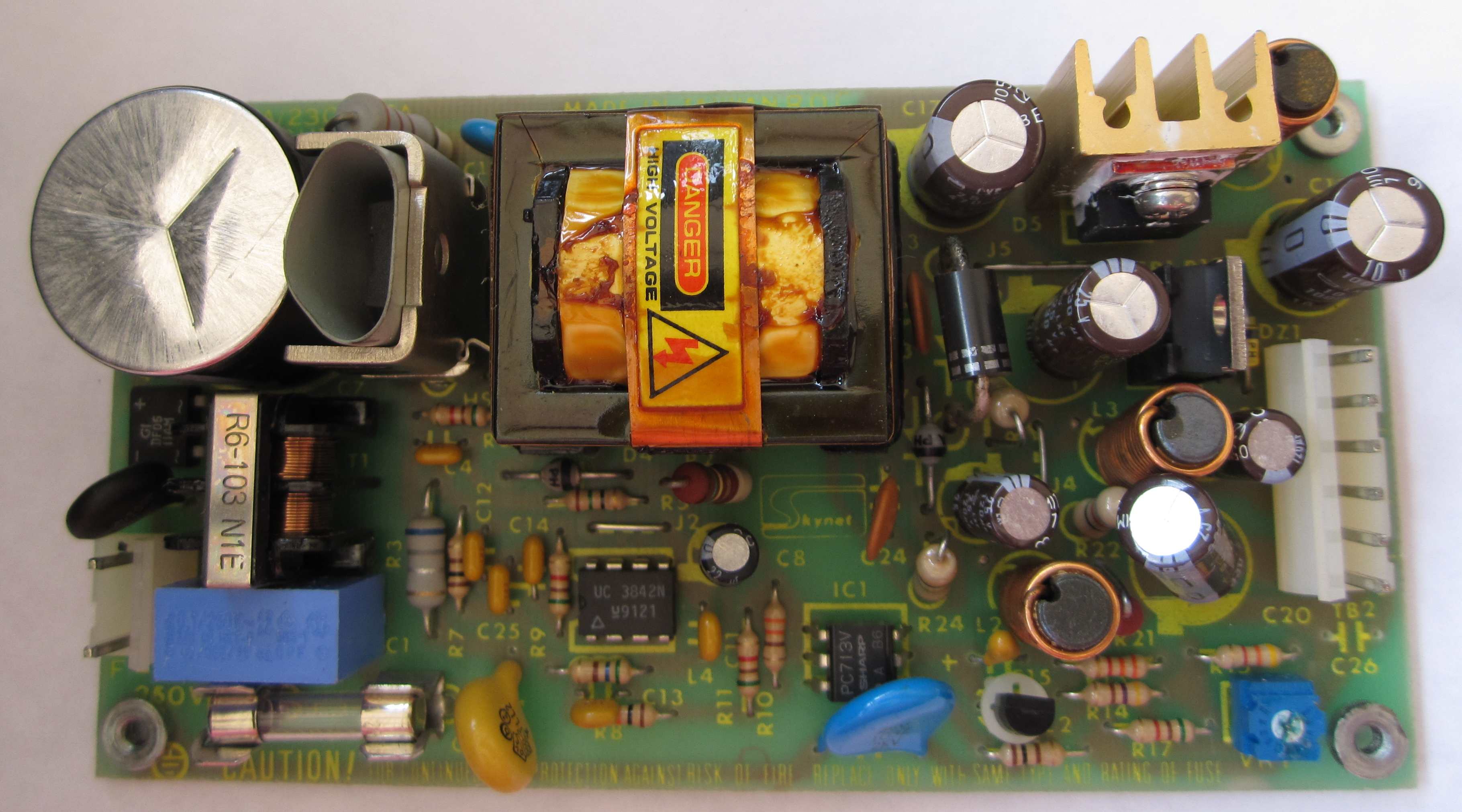
The PSU removed from the steel mounting tube
The
PSU was manufactured by "Skynet",
Model Number SNP-3032
Input specifications: 120V-1A, 240V-0.5A, 50/60Hz.
Output specifications;
V1: +5V/2A, V2: +12V/1.5A, V3: -5V/.3A. |
 |
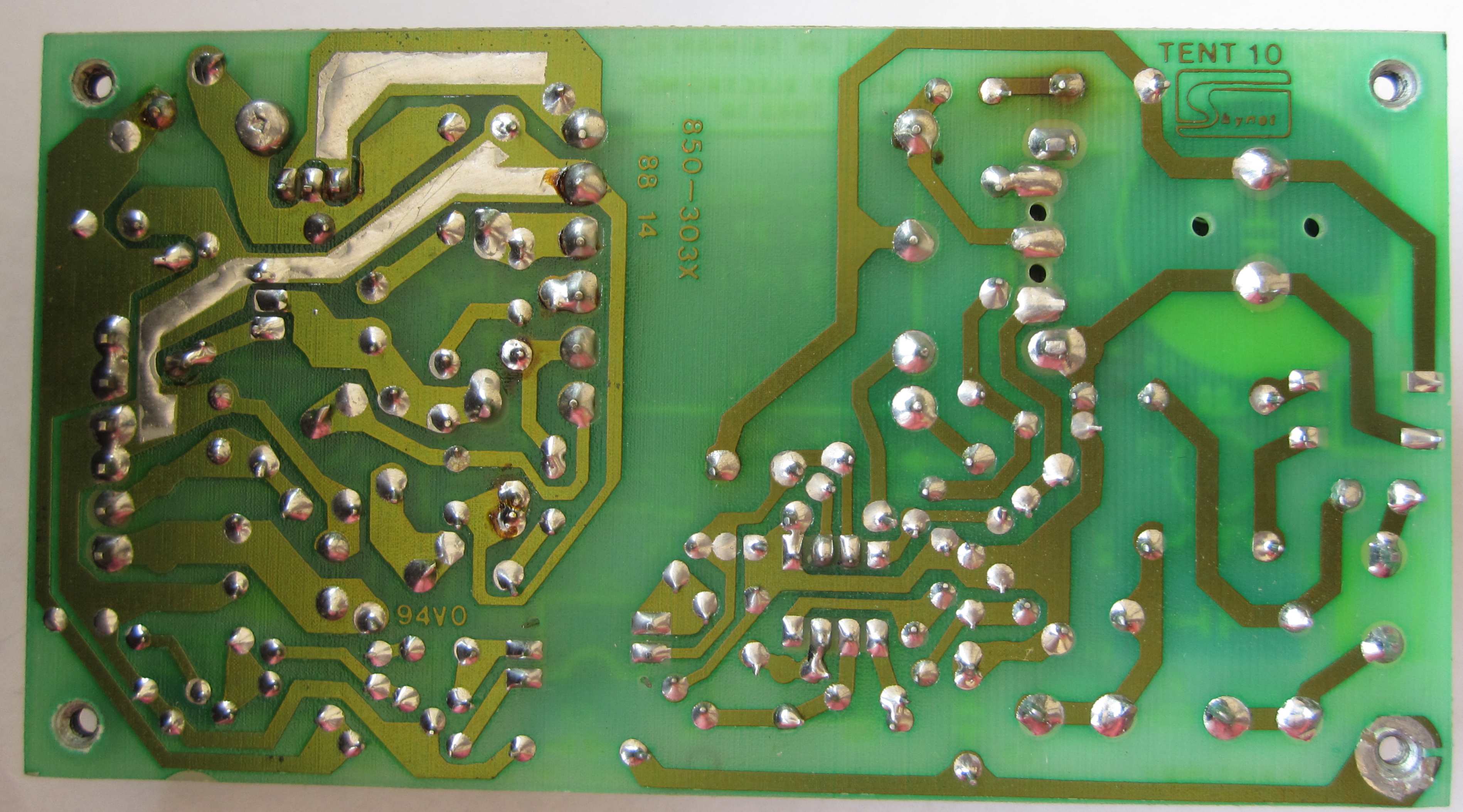
| Solder side of the PSU |
 |
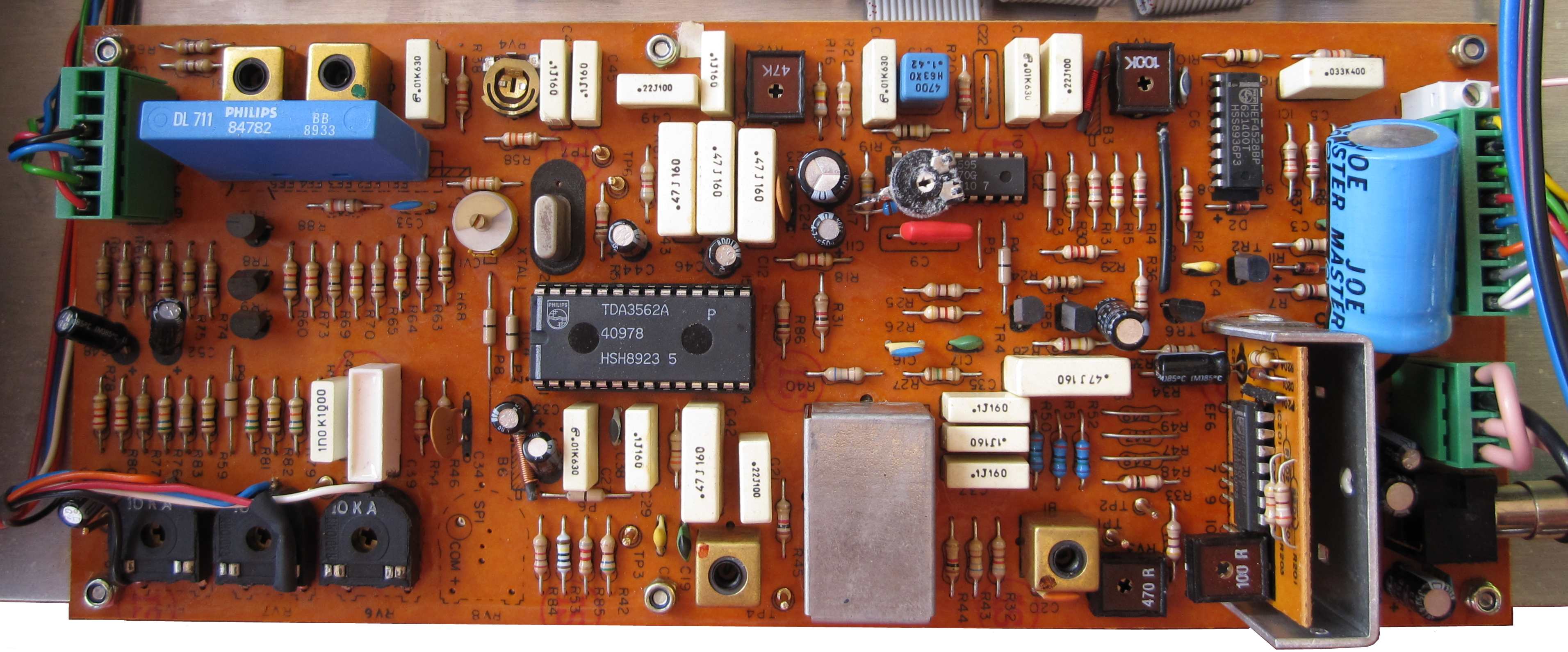
| The Decoder board from fourth Video Decoder /
Distribution Amplifier. You can see a large capacitor on
this board that must have been added as part of the PSU
modification. |
 |
| A close up of another strange modification to this Decoder
board, all of the Decoder boards have fixed and
variable resistors soldered to some of the legs of IC2. This one
has the odd "furring" on the surface of the variable resistor. It
may be something to do with the particular resistor type, as it
always seems to be the black ones that display these surface
"deposits". |
 |
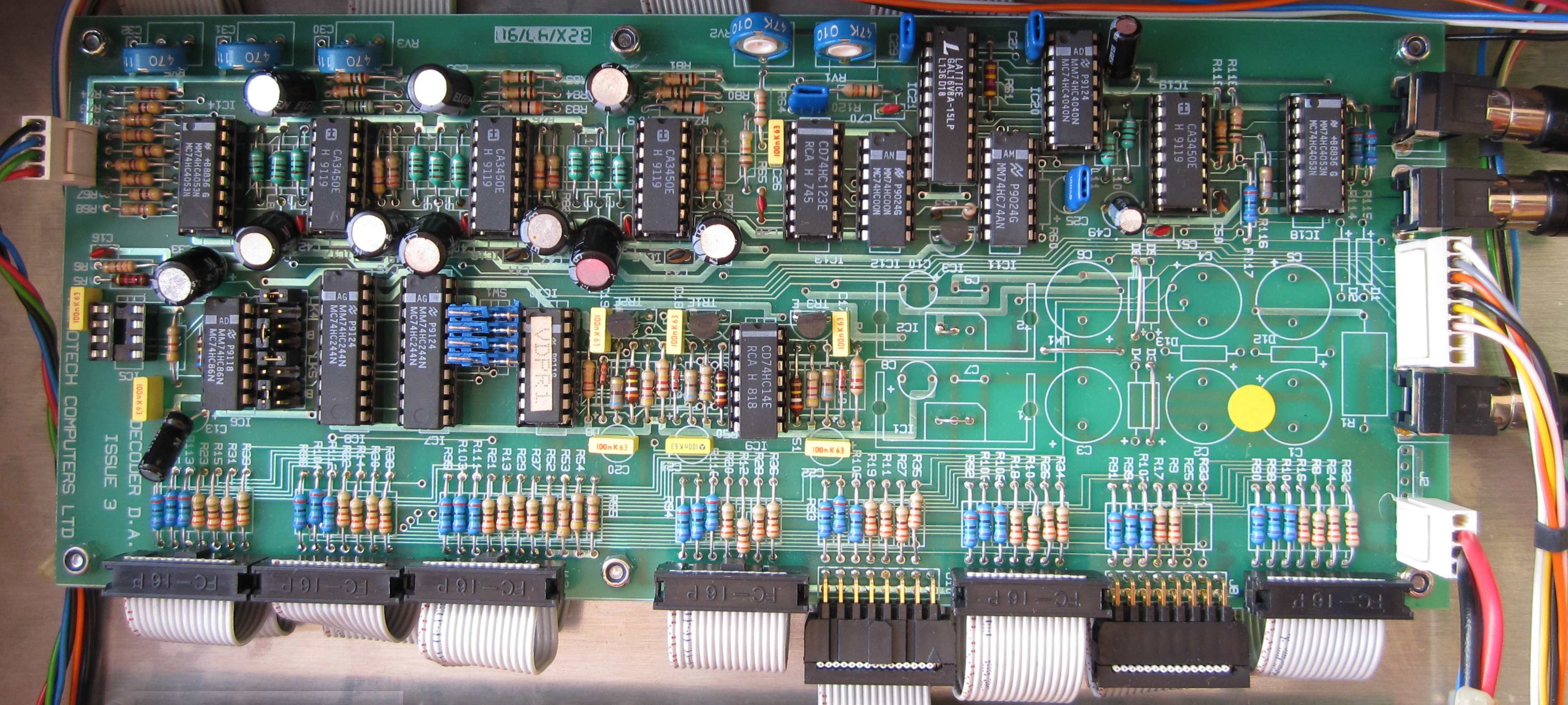
| The Distribution Amplifier from the fourth Video Decoder /
Distribution Amplifier. Although still labelled as an
"Issue 3" board, all of the power supply components have been
omitted since their function has been replaced by the new PSU. |
 |
|
The
Reflex Controller
(Working : after the failed PSU and RAM were
replaced) |
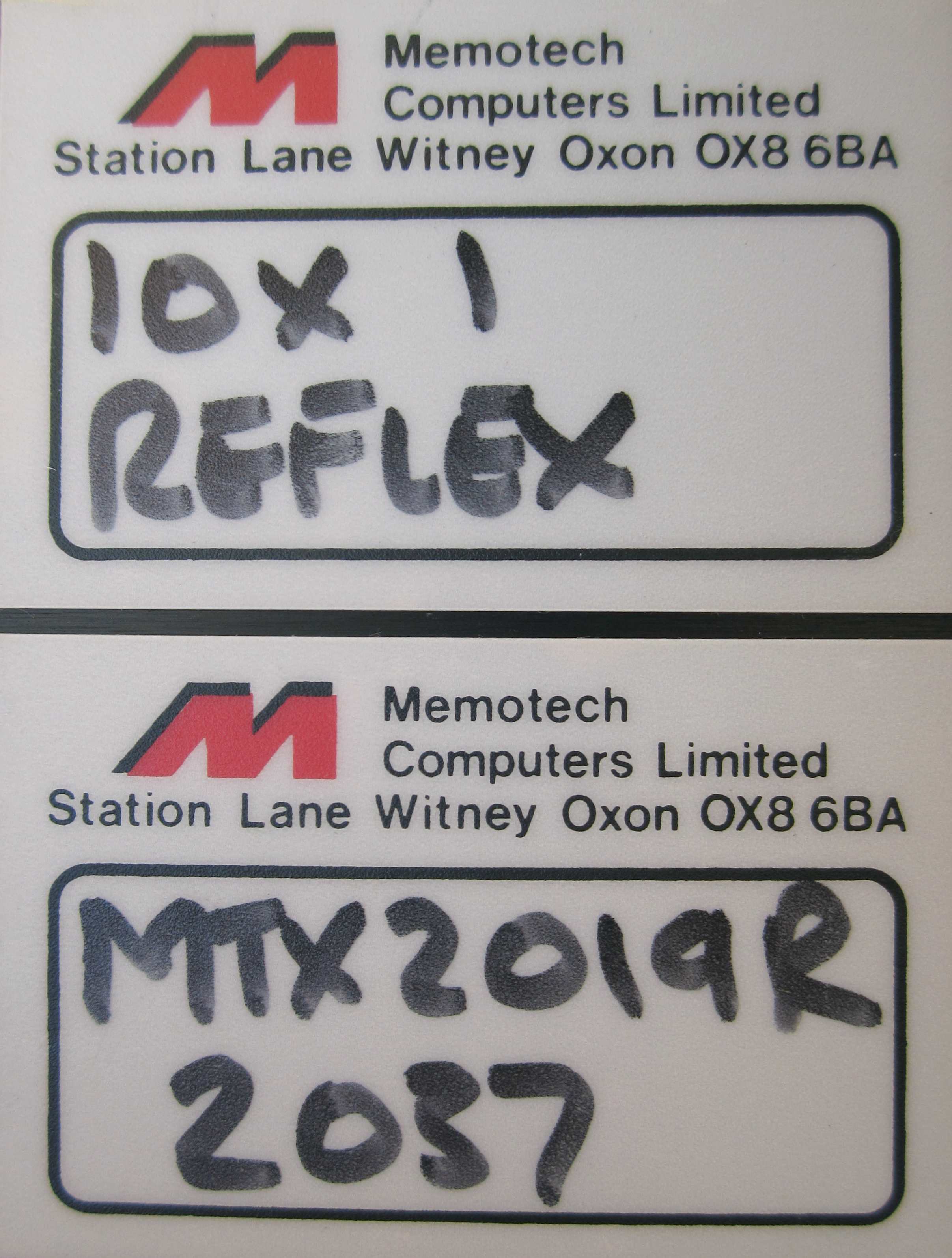
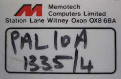
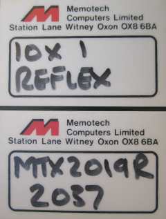
| The last "black box" in my Video Wall bundle. Yes,
another label photo - but at least this time, I think it, or rather,
they are definitely worth showing. The top label describes it as a "10
x 1 Reflex", the bottom label ("MTX2019R") is
the model number and is the same as the model number printed on the
rear of the case.
This is the only item in my Video Wall collection that I have not
previously at least seen a photograph of. In the April 1990 issue of
Lighting & Sound International", available on the
Articles page, the
installation of a Memotech Video Wall as part of the sound &
lighting upgrades to the
Hammersmith Palais in 1990 is described. The article
briefly mentions the "Reflex Touch Controller", it
allowed the operator/DJ to instantly access pre-programmed Video
Wall sequences using a 32 button keypad. Unfortunately, my system is
missing this separate keypad.
(Originally installed by Cameron as two 5x5 Video
Walls, the Palais system was upgraded by Memotech to a
single 10x5 Wall, at that time, it was the largest club Video Wall
in the UK.) |
 |
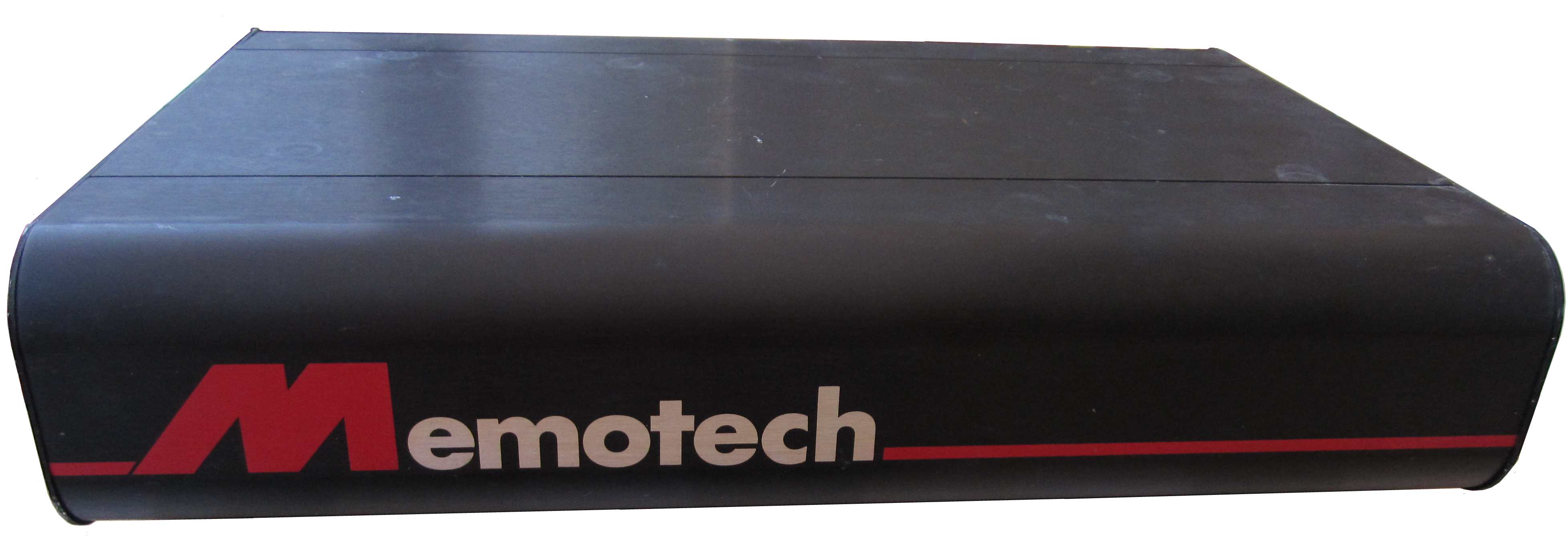
| The front panel of the Reflex Controller.
In the same livery as the Video Decoder /
Distribution Amplifier above. |
 |
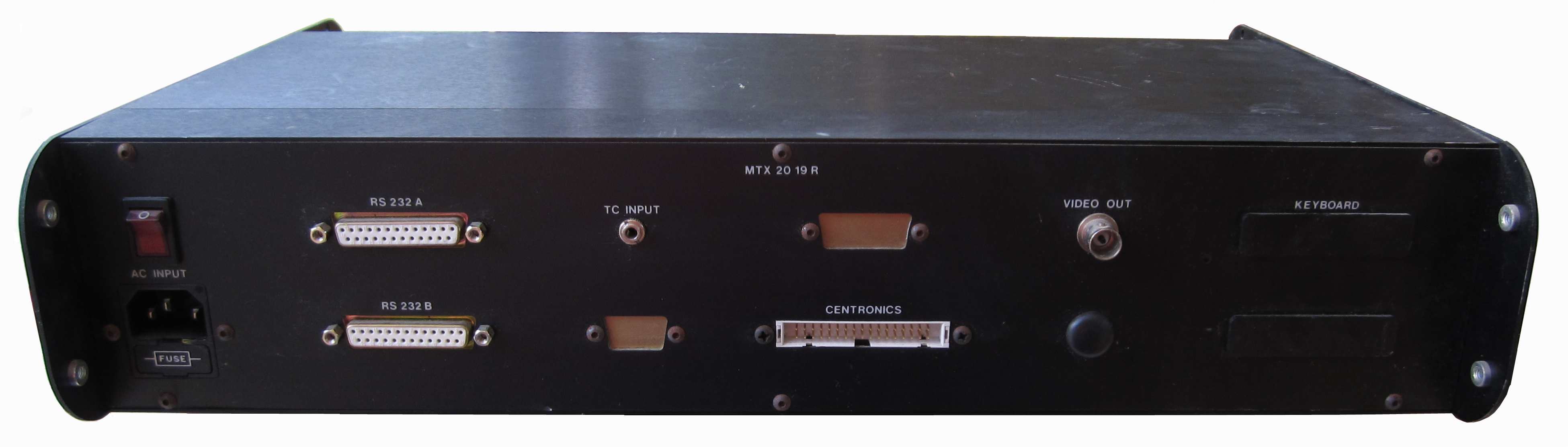
|
The rear panel of the Reflex Controller.
With connectors for 2 x RS232 ports, Centronics interface, Video
Out, as well as one marked "TC". This was for an
EBU/SMPTE
Time Code input. |
 |
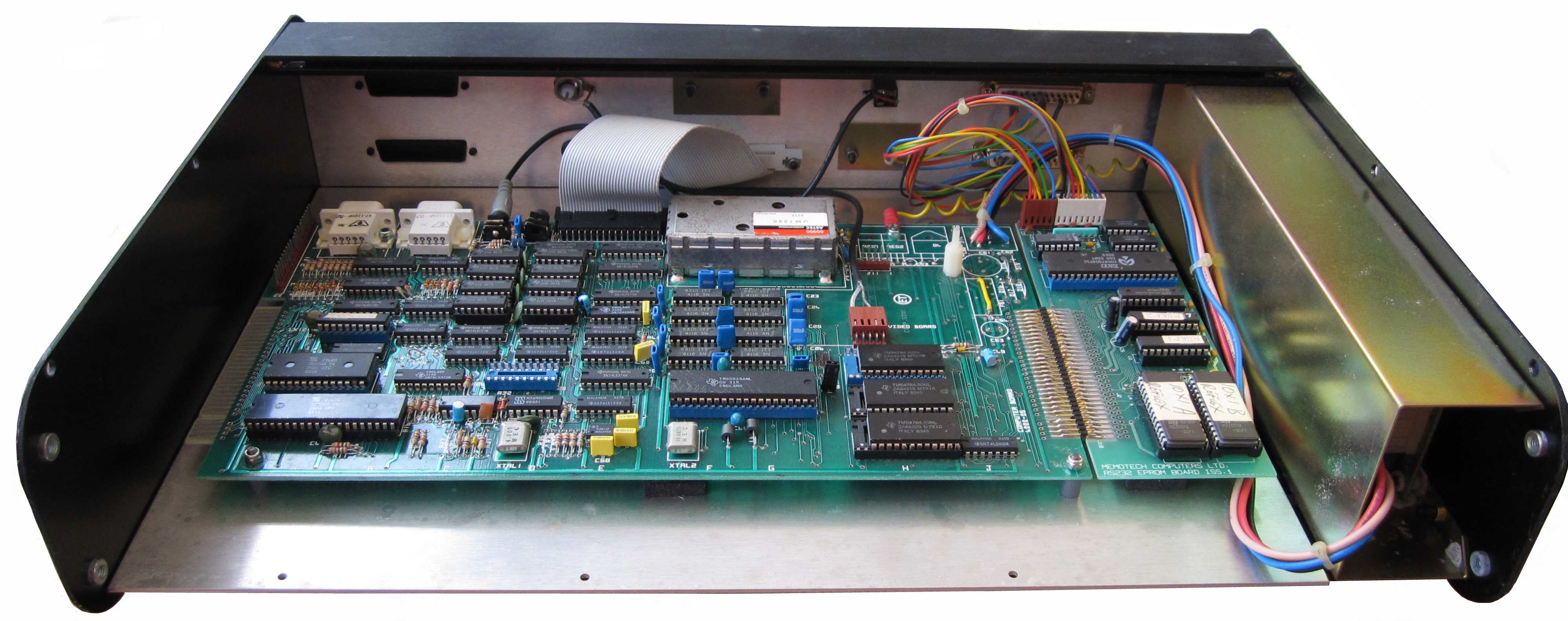
|
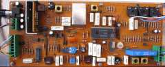
Inside view of the Reflex Controller,
showing a similar PSU as the Decoder above, it is a "Skynet",
Model Number SNP-3031.
Input specifications:
120V-1A, 240V- 0.5A, 50/60Hz.
Output specifications;
V1: +5V/2A, V2: +12V/1.5A, V3: -12V/0.3A.
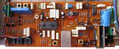
Does the
main PCB look vaguely familiar? It should do, it is a MTX 4000-05
Computer board, with 256k of memory, but with no Video board and a
previously unseen combined RS232 and ROM board. |
 |
|
Component side of the MTX Computer and RS232/ROM boards.
The external Time Code input is connected to the MTX Tape Input
jack and with no Video board fitted, the monitor output is connected
to J3, where the MTX video board would normally have been connected. |
 |
| Solder side of the Reflex Controller
circuit boards |
 |
| The 4000-05 Computer board with 256k of RAM A mono
video signal is being "fudged" by taking the Component video "Y"
signal from J3 Pin 5 directly to the Video Out connector (see my
MTX Video page).
With
the DC PSU fitted, the regulation and smoothing components are not
fitted to this board - a model for the proposed MTX PSU replacement
I wonder? |
 |
| Solder side of the MTX 4000-05 Computer Board, as it
has 256K of RAM installed, the expected yellow wires are present
too. |
 |
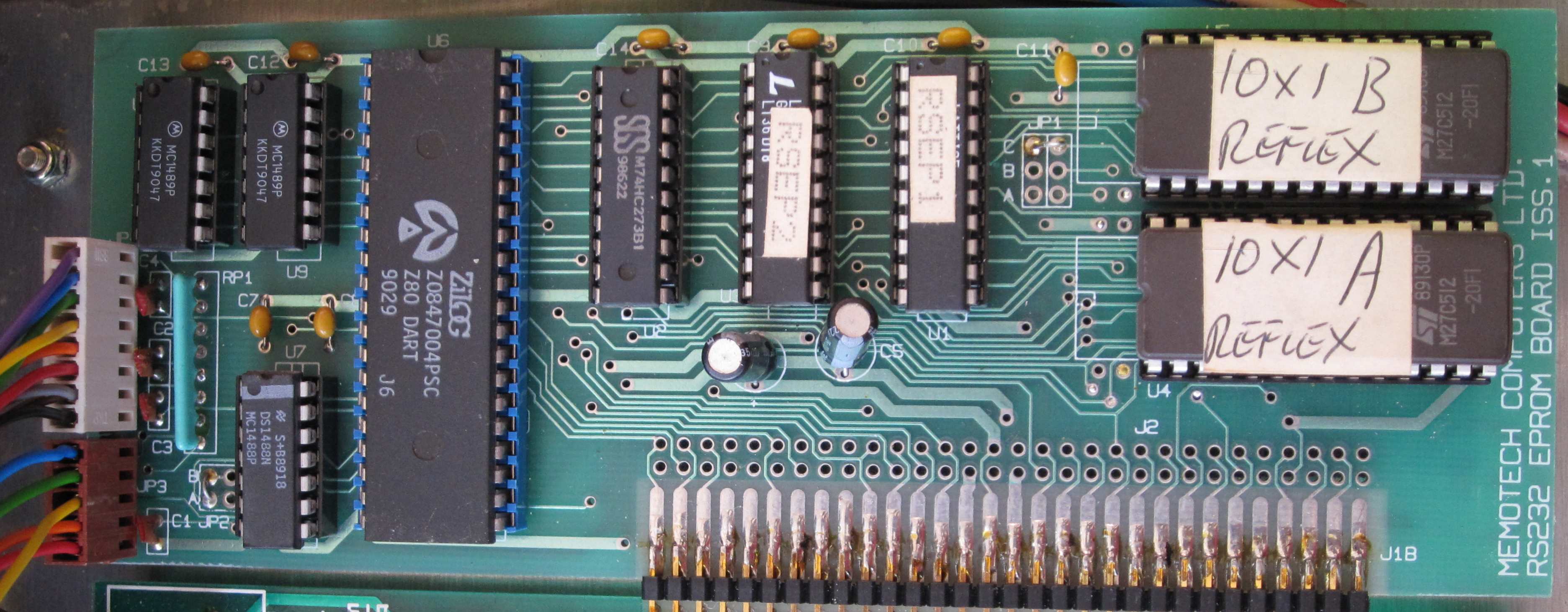
| The combined RS232 / ROM board |
 |
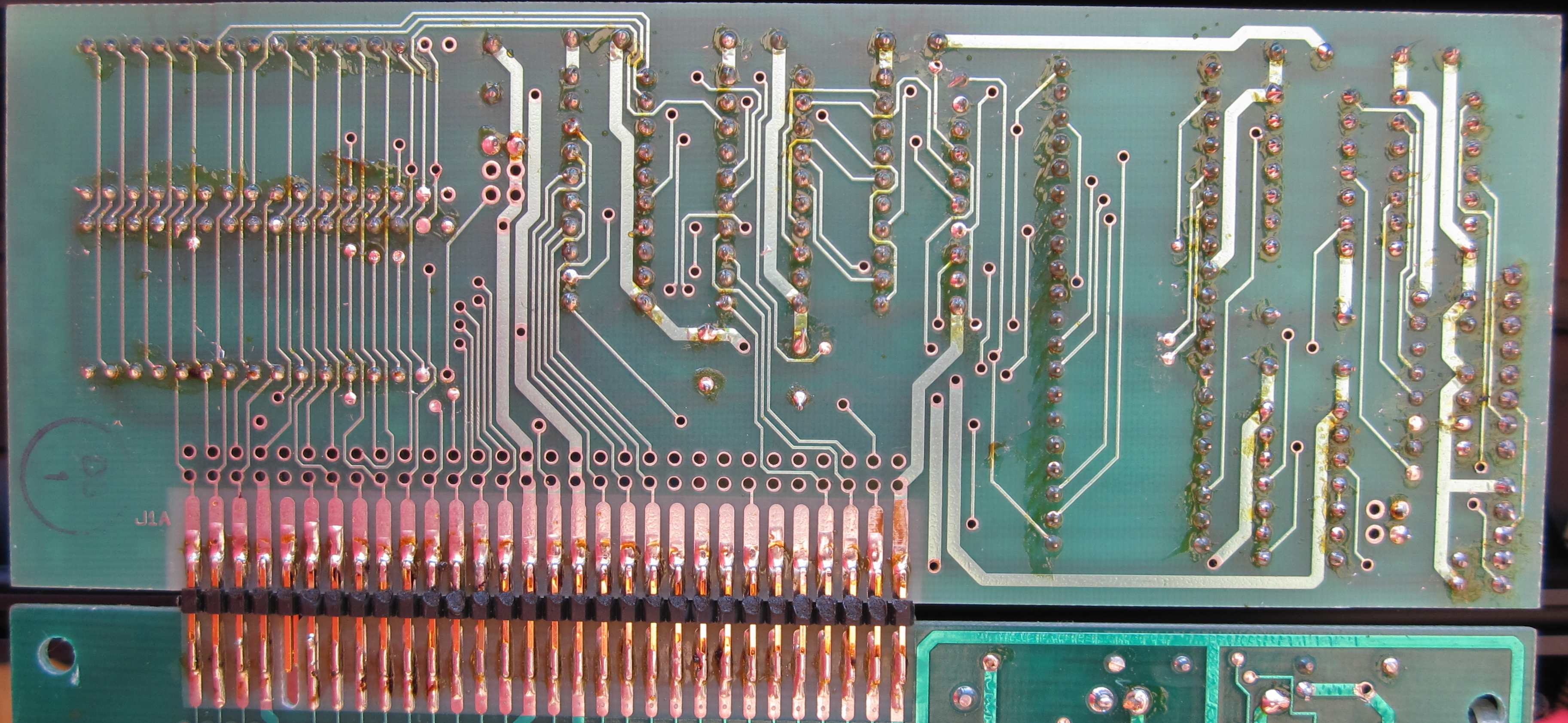
| Solder side of the RS232 / ROM board |
 |
| When I tried to power it on, I discovered that the Reflex Controller had a failed
PSU and subsequently discovered that faulty RAM on the MTX computer
board also prevented it from working, until I repaired it as
described on this
page.
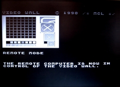
The Reflex was configured to operate from ROM; on
start-up, a RAM disk was created from the computer's RAM and the
Video Wall operating program and sequences were copied form ROM to
RAM, the software auto-started and the Reflex was put
into remote mode to allow control of the Video Wall from an external
device / computer. The expected prompt monitor display is shown
here. |
 |
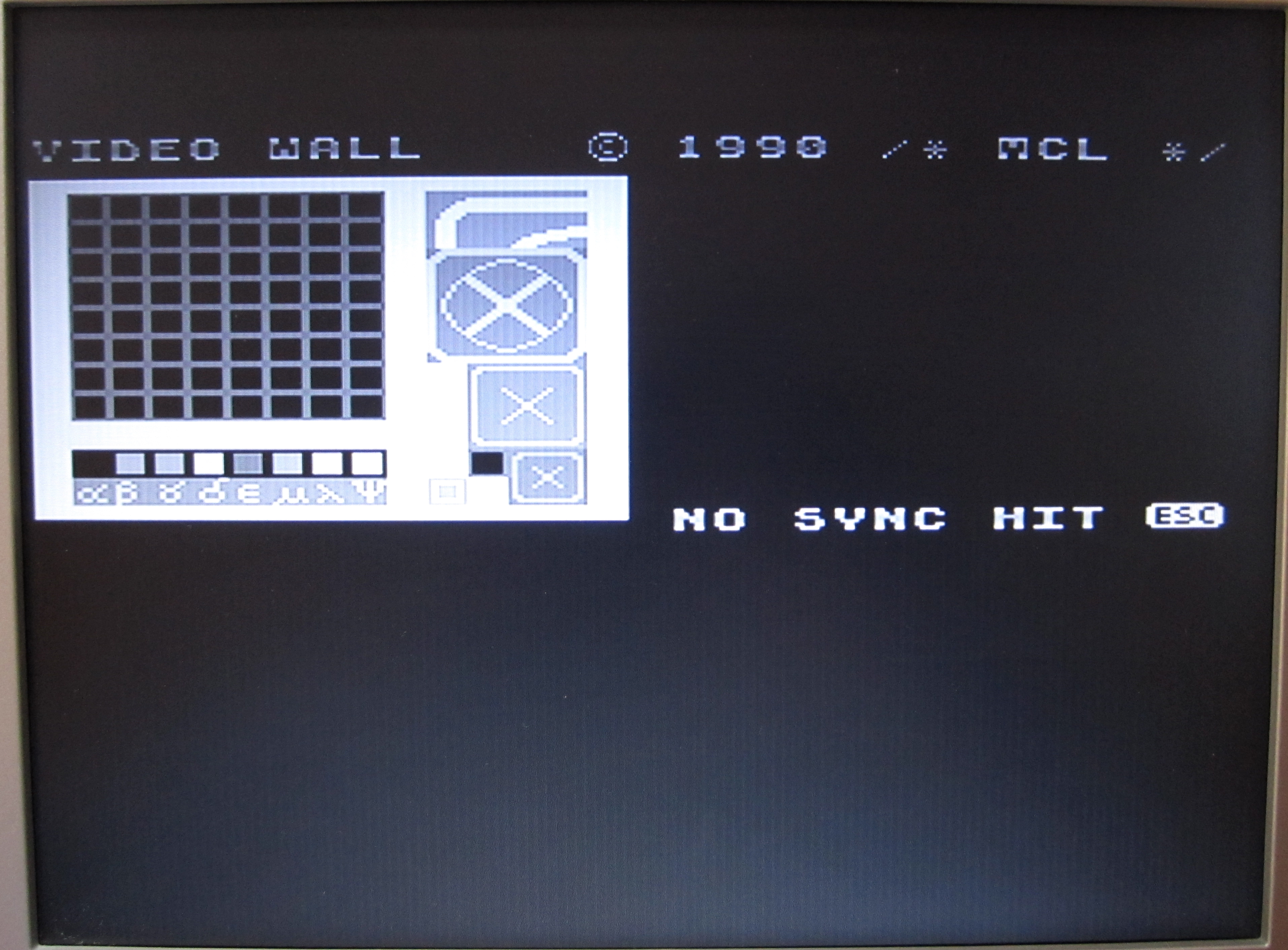
| With no DDFS(s) connected when the
Reflex boots, a "NO SYNC"
error message is displayed on the prompt monitor, along with the "HIT (ESC)"
prompt. This would have been problematic when the Video Wall was in
use as the Reflex does not have a keyboard or even a
keyboard connector fitted. With this error displayed, I found that
it is not possible to "Take Control" of the system remotely.
During my testing though, I was able to have an MTX keyboard
connected via the usual MTX computer board keyboard header. |
 |
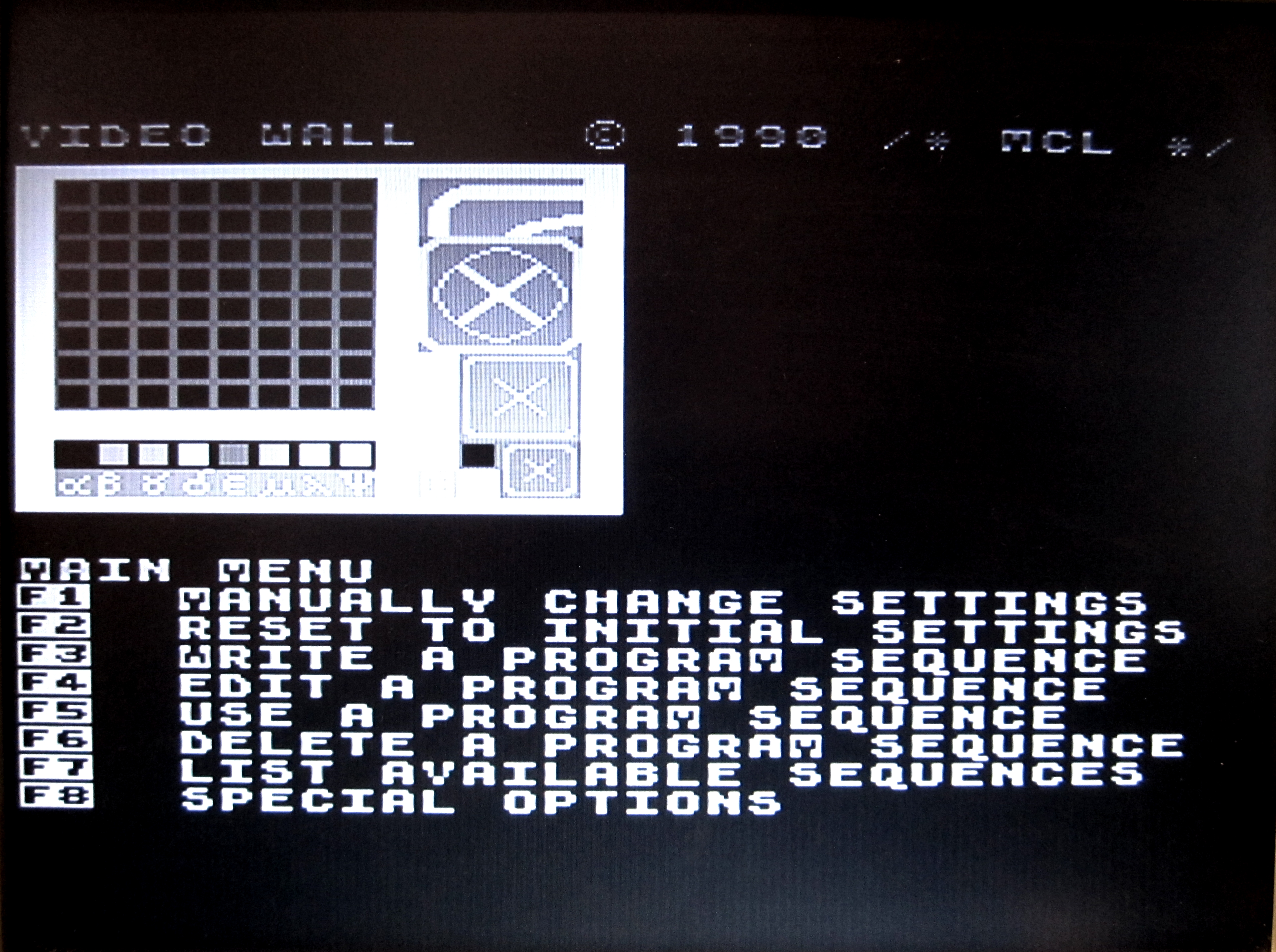
| On pressing the <ESC>
key, the normal Video Wall "Main Menu" is displayed.
Function key "F8" calls up the "Special
Options" Menu, from where, remote operation can be turned on
using the "F1" function key. |
 |