|
 |
The Memotech MTX Series |
 |
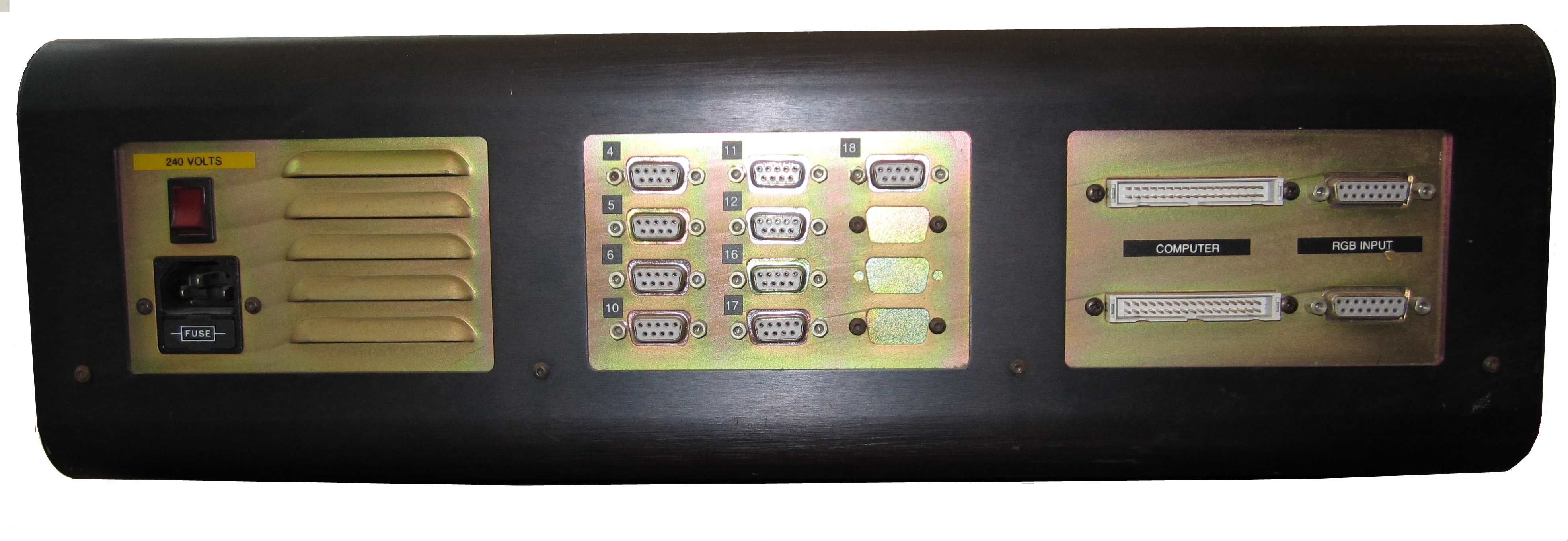
Video Wall DDFS
Power Supply Replacement
The Video Wall DDFS
The heart of the Memotech Video Wall system is the
Distributed Digital Frame Store (DDFS), containing a number (up
to 10) of video frame store boards and their associated
controllers (2 per DDFS). The electronics were powered by
an Astec "SA130-3400", producing, 5V@15A, +12V@5A,-5V@0.7A and
-12V@0.7A.
Unfortunately, the DDFS in the Video Wall system that I bought
in June 2013 was DOA - the power supply was totally dead,
although mains voltage was reaching the PSU and the internal
fuse was intact - there were no DC outputs from the PSU. The
original plan was to repair the PSU, but the job turned into
sourcing and installing a compatible replacement.
|
The Original
DDFS Power Supply (failed) |
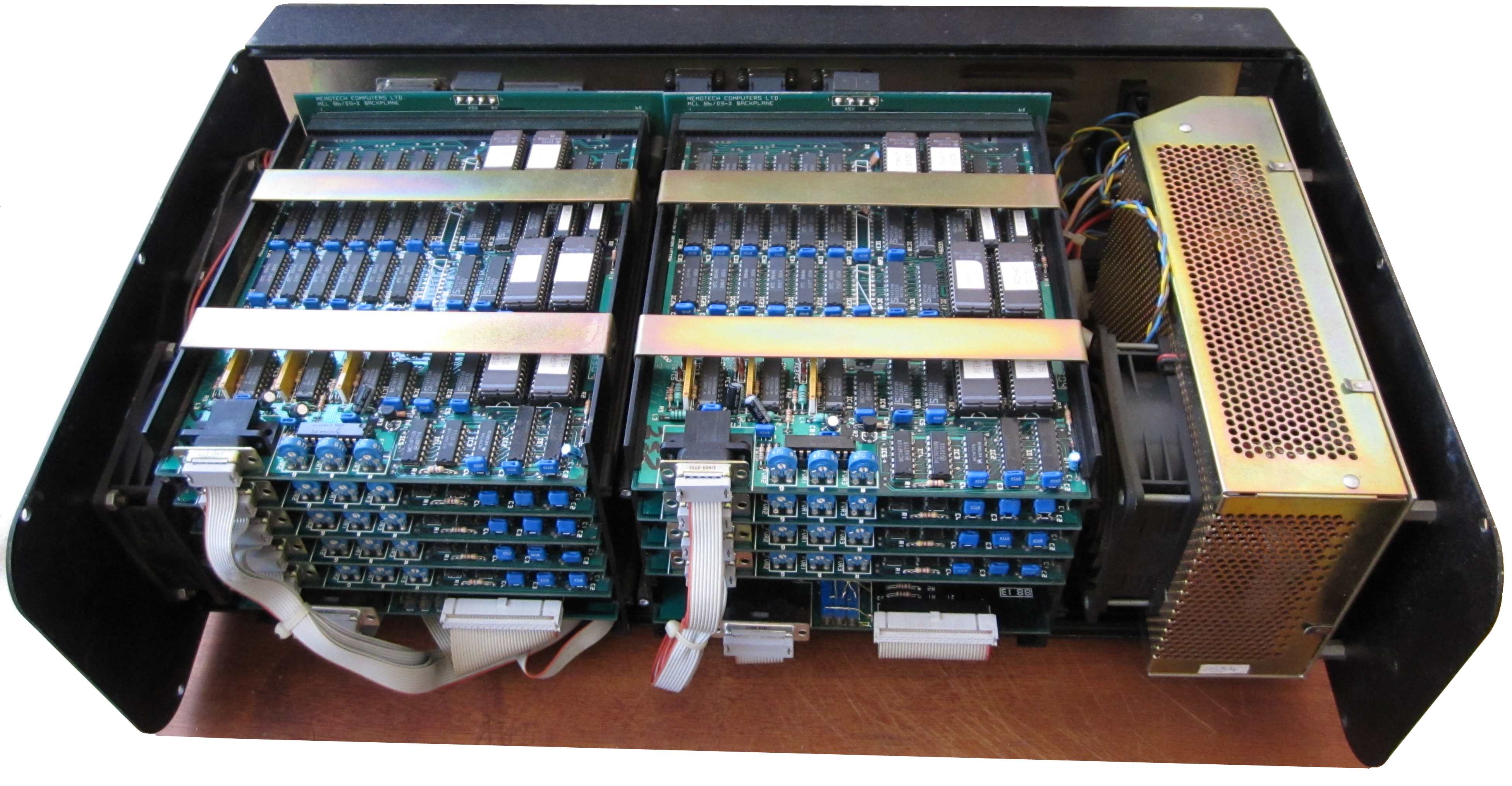
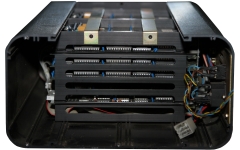
| The PSU is mounted on the reverse side of the
right hand end-plate. Looking into the DDFS with
the right hand end-plate and PSU removed. |
 |
|
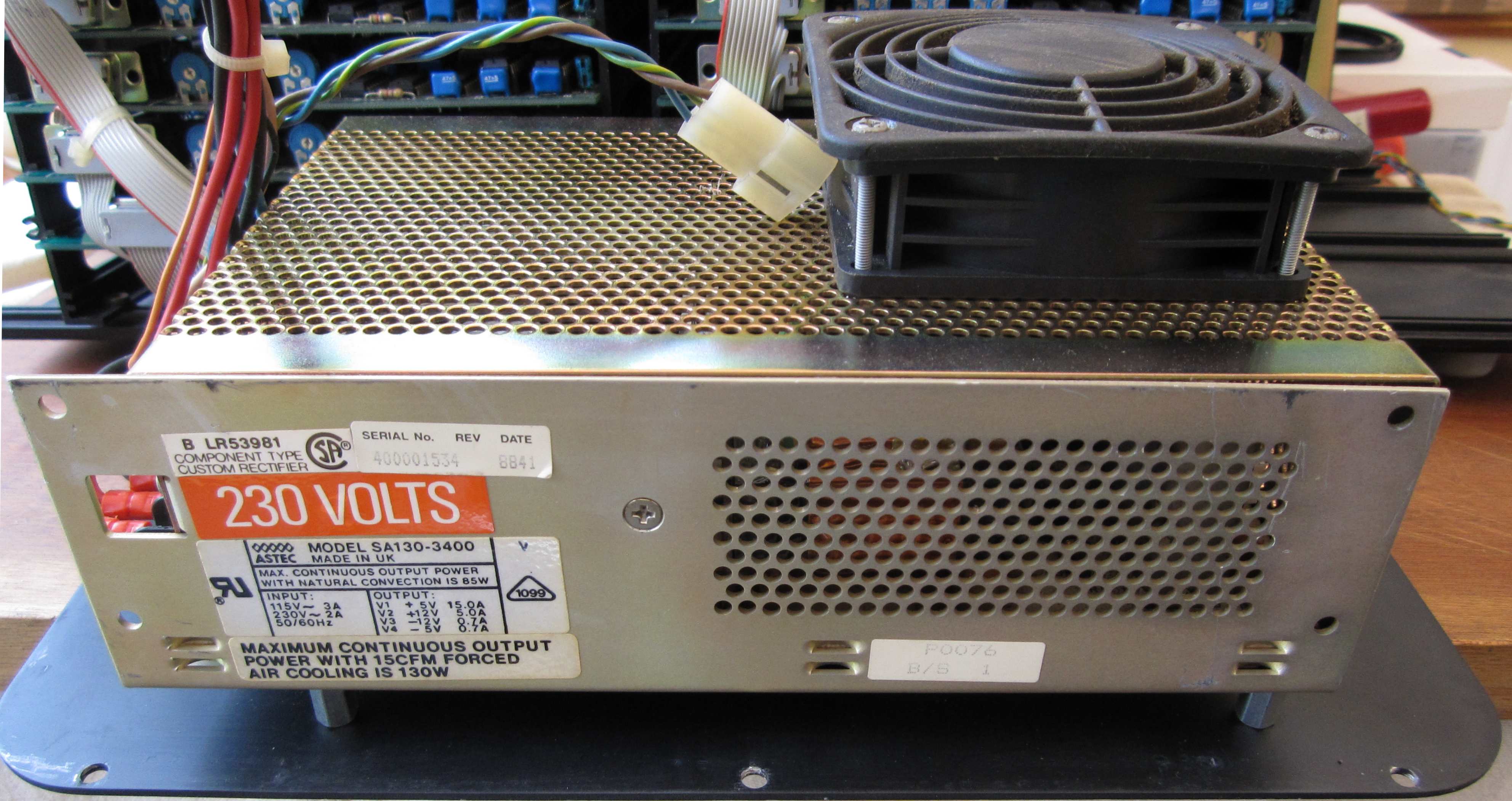
The PSU is an Astec SA130-3400 with 4 outputs
:-
| V1 +12VDC
5A |
V2 +5VD 15A |
|
V3 -12VDC 0.8A |
V4 - -5VDC
0.8A |
|
 |
| As indicated on the data-plate, the maximum
continuous power output is limited by the available
cooling. Using only natural convection, the power
output is limited to 85W, with forced cooling of
15CFM (cubic feet/min), the continuous output rises
to 130W - hence the "130" designation. In the DDFS,
a cooling fan is fitted to the outside of the case
and supplied by the PSU's +12VC power output. |
 |
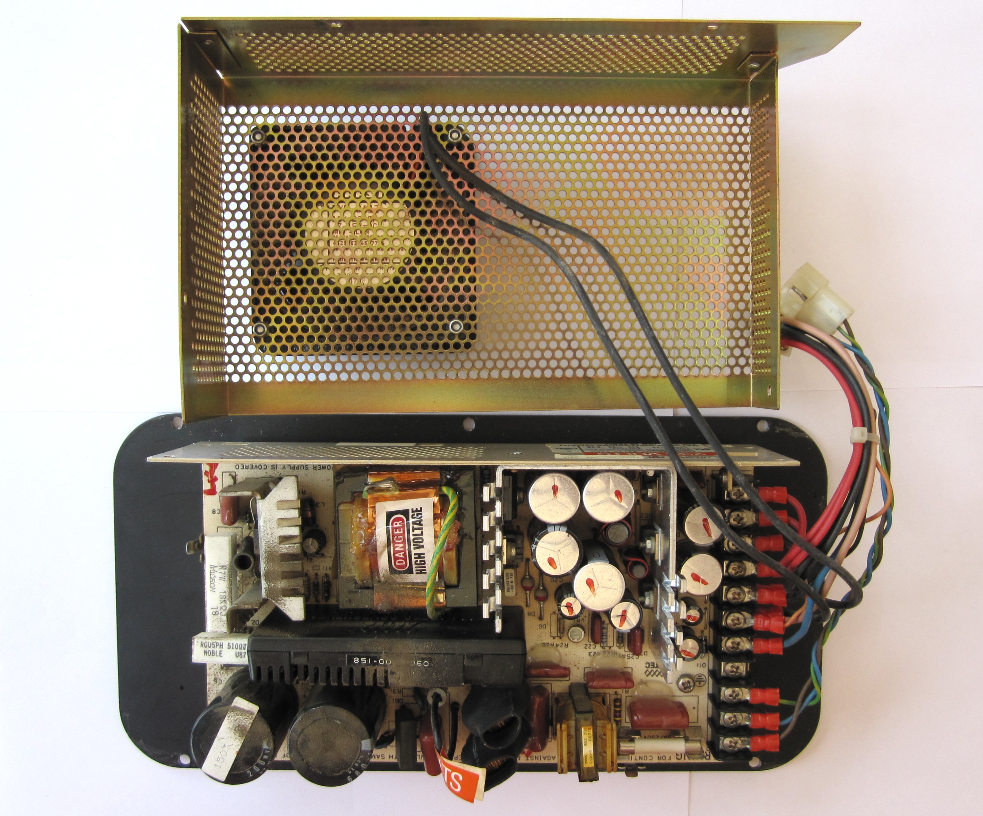
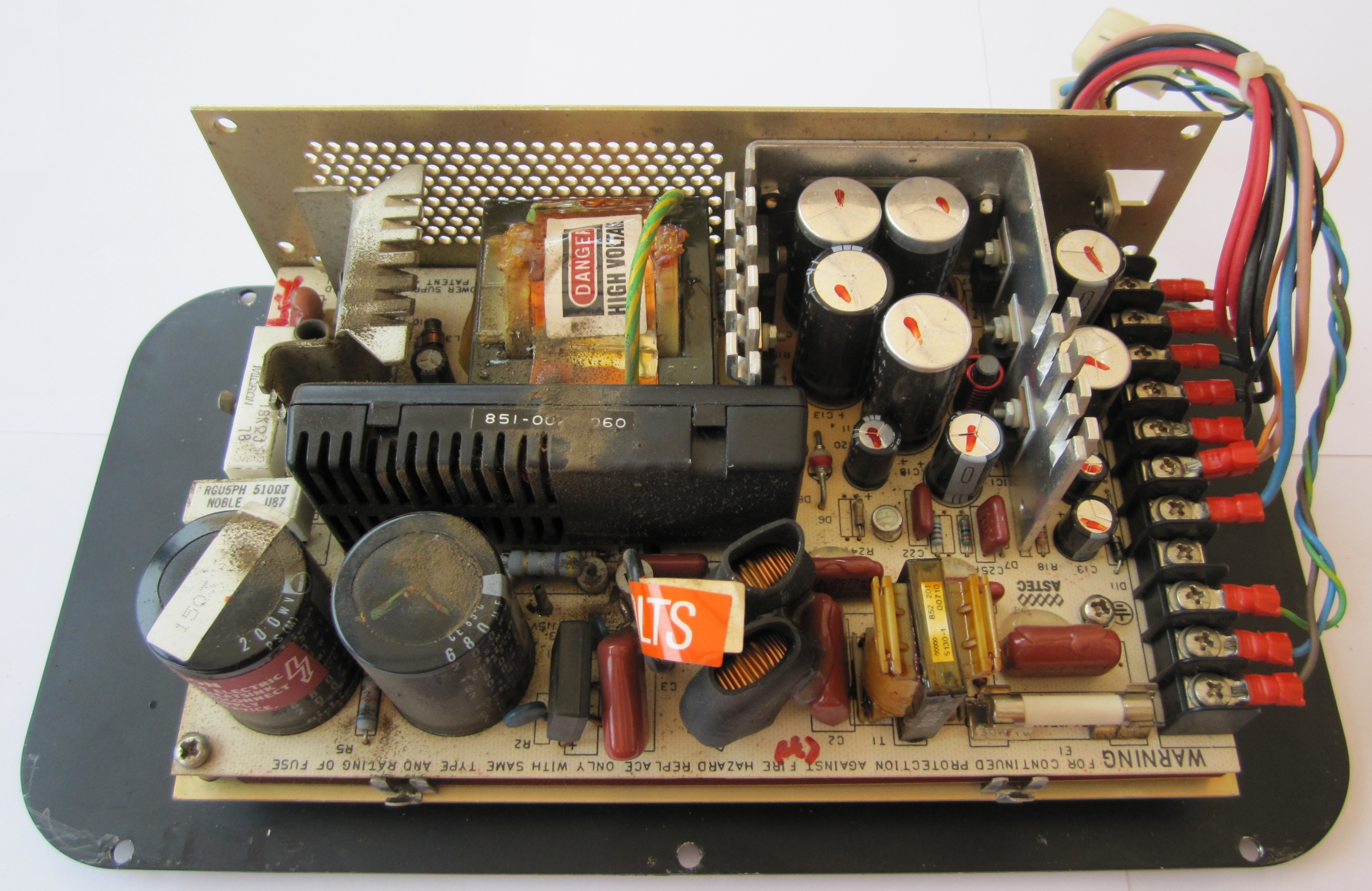
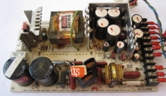
| The cover and fan removed, the PSU frame is
mounted on the DDFS end plate using 4 x 3/4" metal
stand offs and the PCB is secured to the base plate
by 2 crosshead screws.
The PCB is also secured to the side of the frame
by two screws through the front into the large
aluminium heat sink to dissipate heat from the power
transistors. |
 |
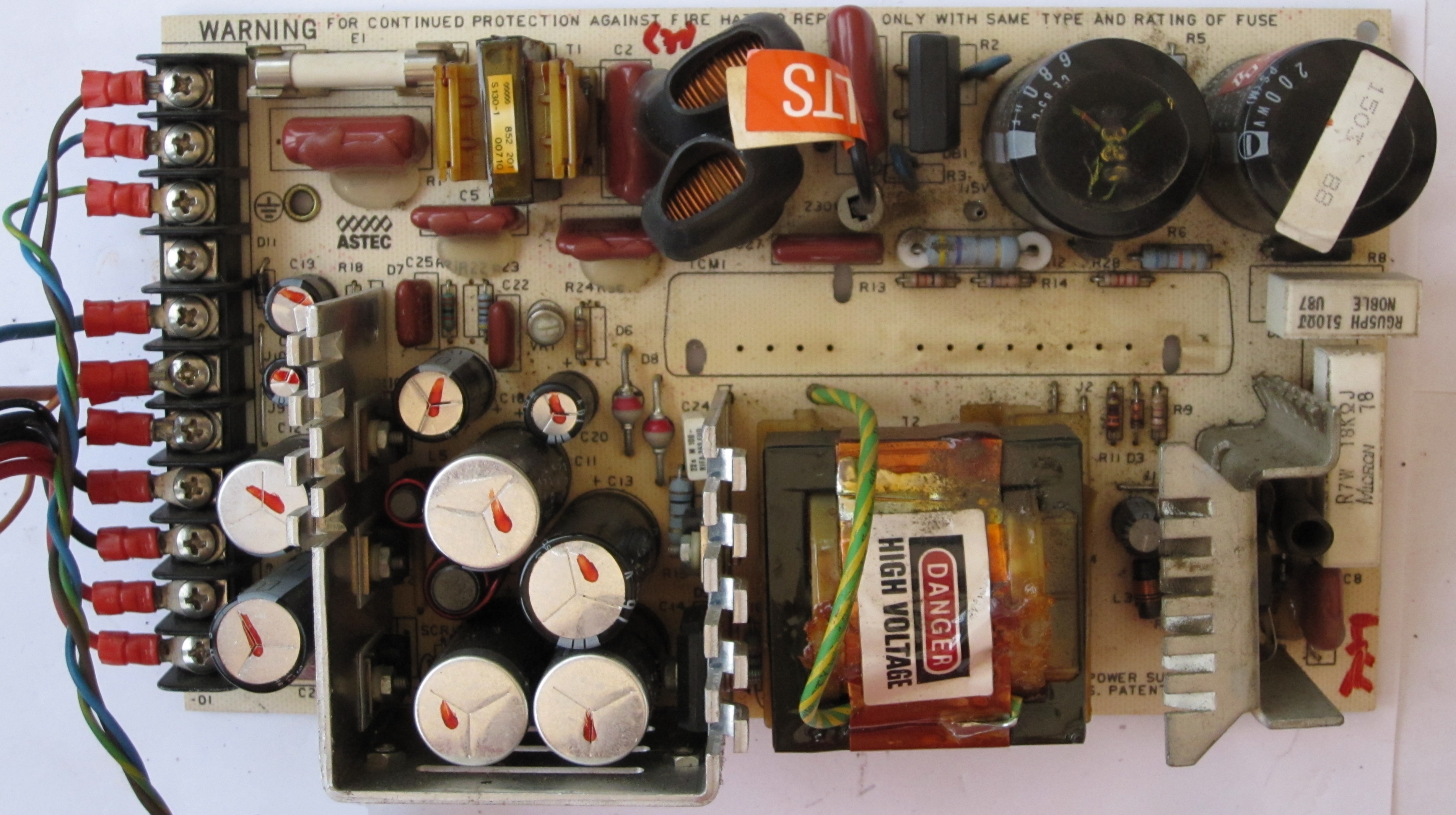
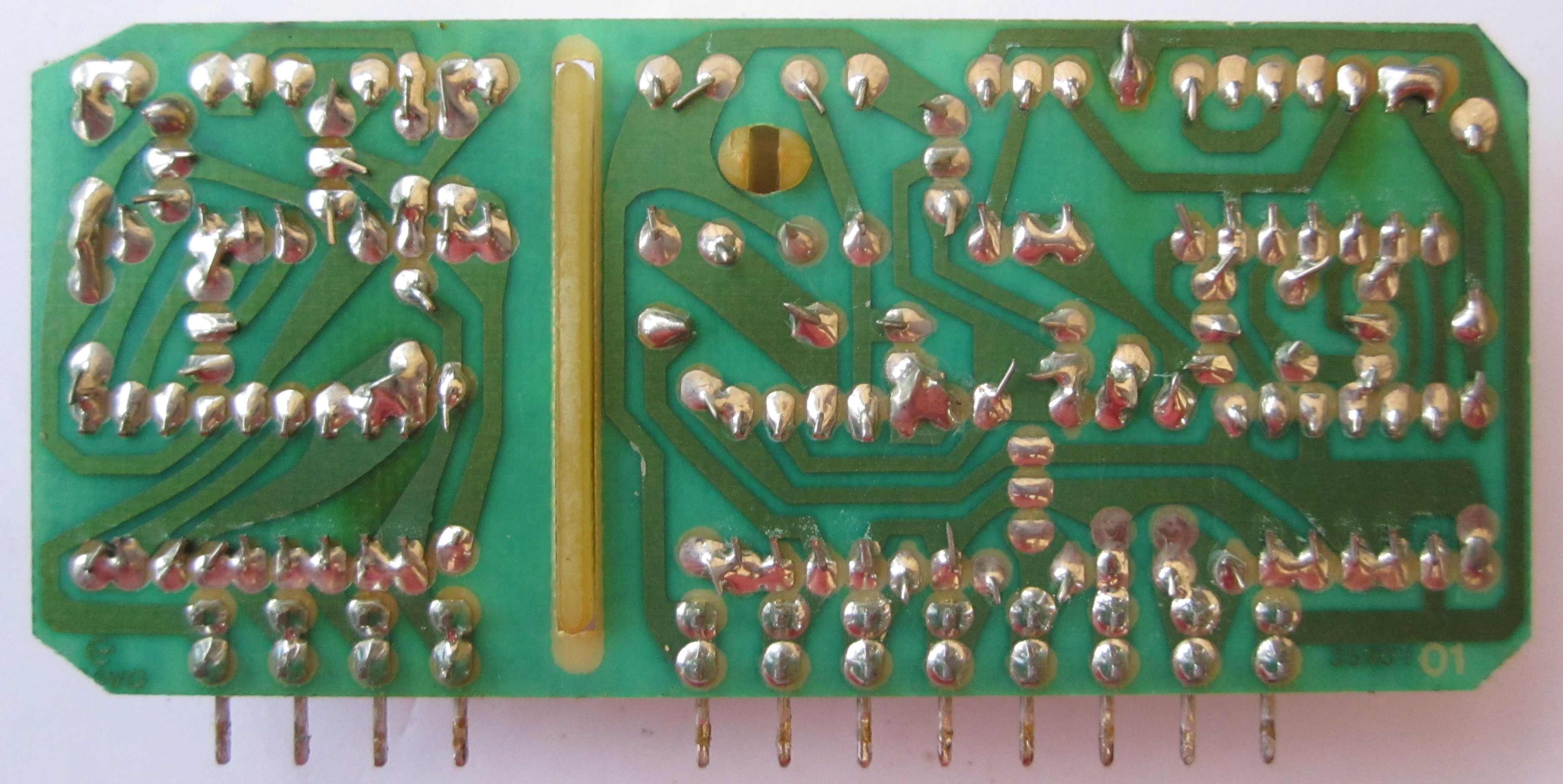
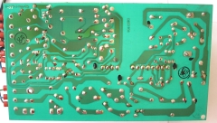
| The PCB removed from the frame showing the
solder side. The 3 black plastic lugs and 12 (4 +
8) solder connections secure the control module (the
black plastic cartridge visible in the photo above)
to the PCB. |
 |
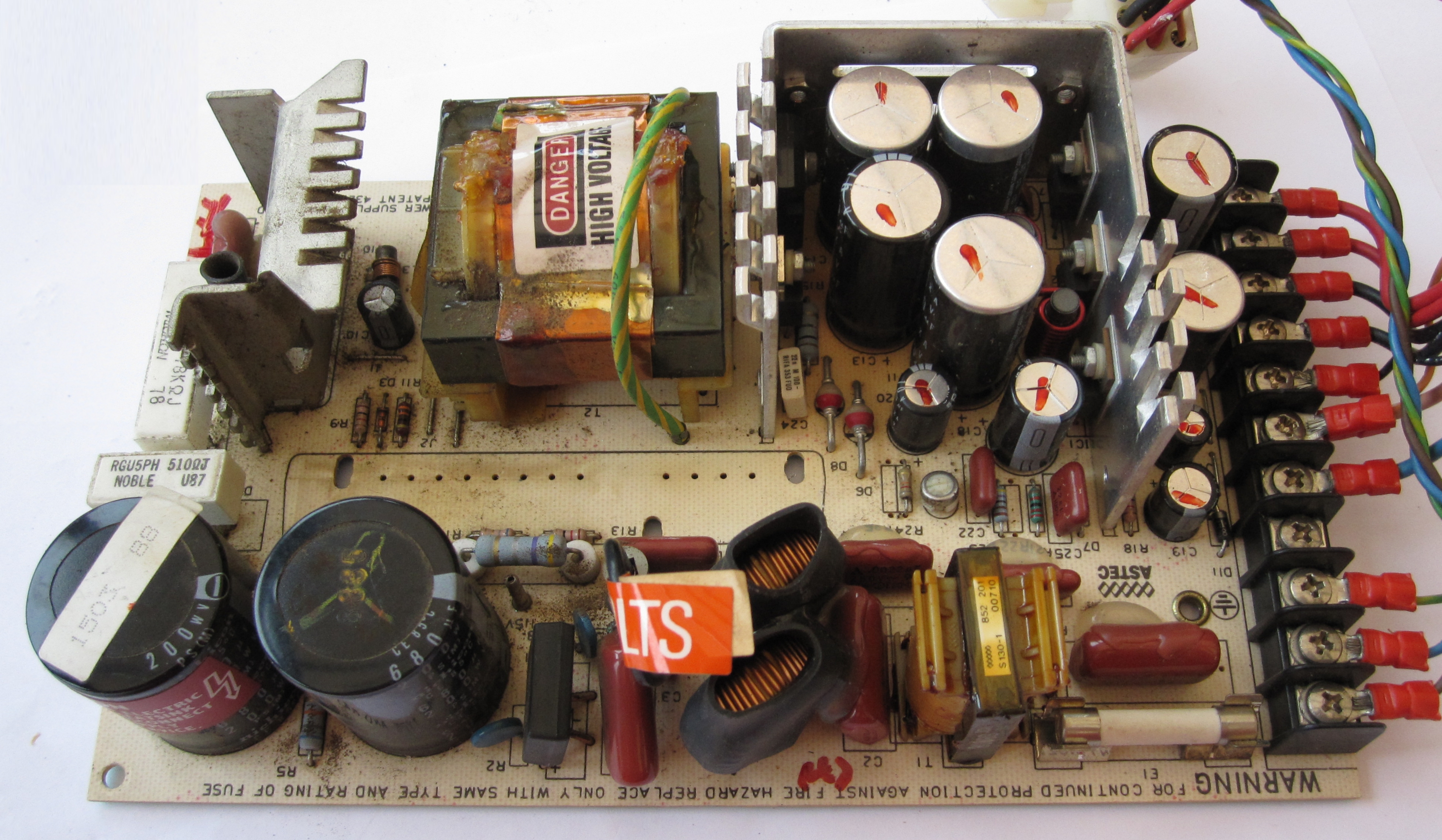
| With no obvious damage to the components on the
main PCB, I decided to remove the control module for
inspection. Unsoldering the 12 connections through
the PCB and springing the plastic lugs allowed the
control module to be removed as shown. |
 |
| View from the other side |
 |
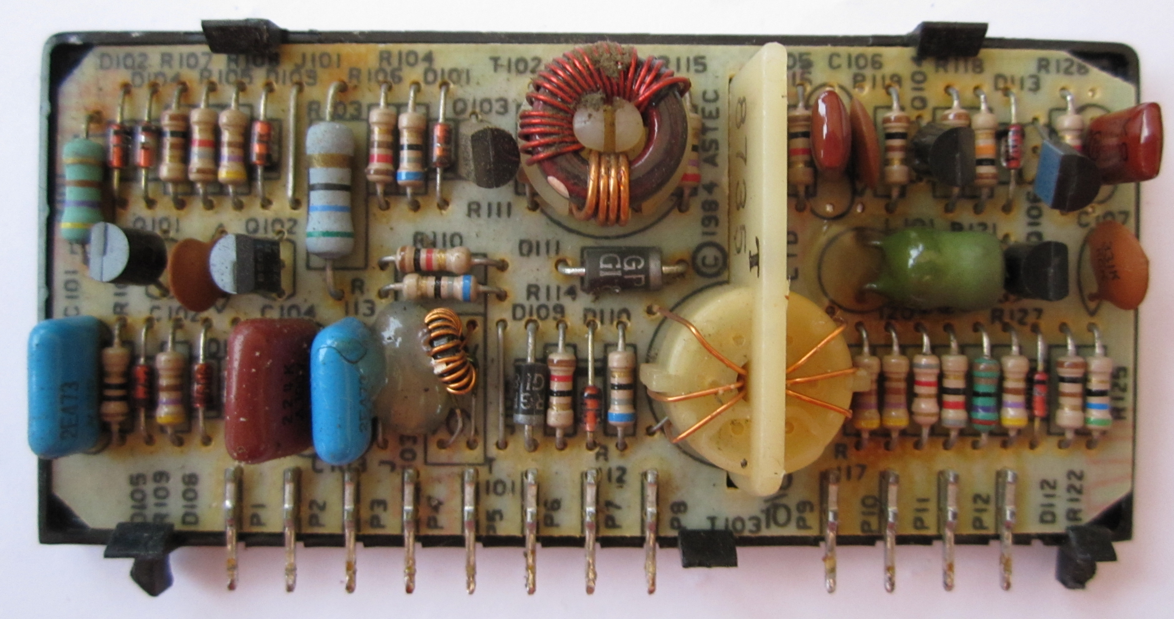
| The control board removed from the cartridge,
again, with no obvious damage to any of the
components. The module has an Astec part number on
it, 851-00201060, but I have not been able to find
any reference to that part number on the internet. |
 |
| Solder side of the control board PCB |
 |
Unsurprisingly, the SA130-3400 is obsolete and I was unable
to find any technical or service data on the internet that would
allow me to make an attempt at repairing the PSU. (Astec are now
a division of
Emerson, I did try to get some technical information from
the
Emerson Embedded Power Systems technical support group, who
did try to help, but due to the age of the PSU, were only able
to locate a
product data sheet, but no service details.) A quick
"Google" showed that there were a number of companies in the UK
who could potentially repair the PSU but the costs were likely
to be of the order of £50 or more and I was given one quote for
£150-£200!
Given that I was unsure of the status of the rest of
the hardware, I couldn't justify this
cost, so I looked around for a compatible supply that could be
fitted inside the DDFS case.
The obvious potential replacement PSU was a
micro ATX power supply. As well as the power on signal,
standby and control voltages, the original ATX specification
included +12V, +5V, +3.3V, -5V and -12V. Later revisions of
the specification removed the -5V supply, so newer models of
ATX PSU do not have a -5V output. However, I was able to
find a used micro ATX PSU which supplied the required
voltages, albeit with lower current capacity on the negative
voltages, 0.5A at -12V and 0.3A at -5V. Closer investigation
of the DDFS power distribution revealed that the -12V supply
was not actually used and, having looked at the details of
the PCBs in the DDFS, Tony Brewer was able to confirm that
the actual -5V load would be trivial - certainly much less
than 0.3A.
|
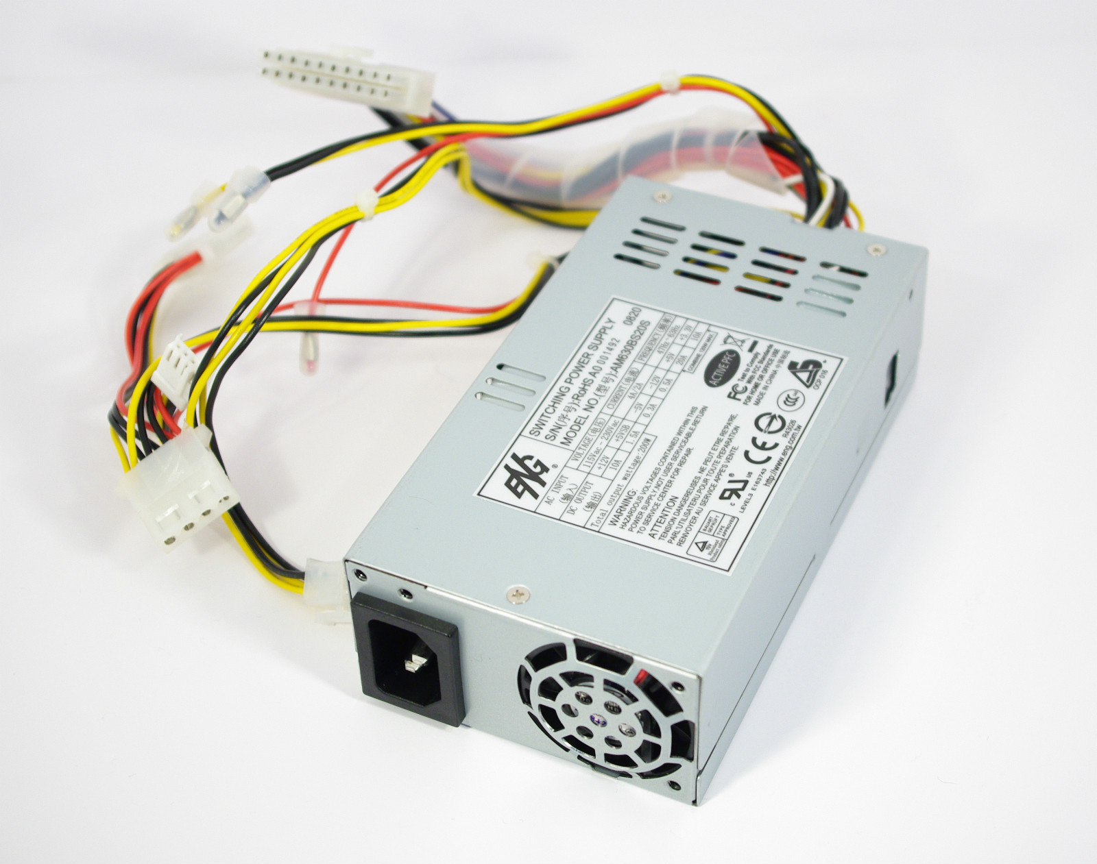
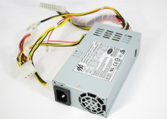
Replacement Power Supply |
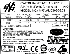
| The replacement micro ATX PSU |
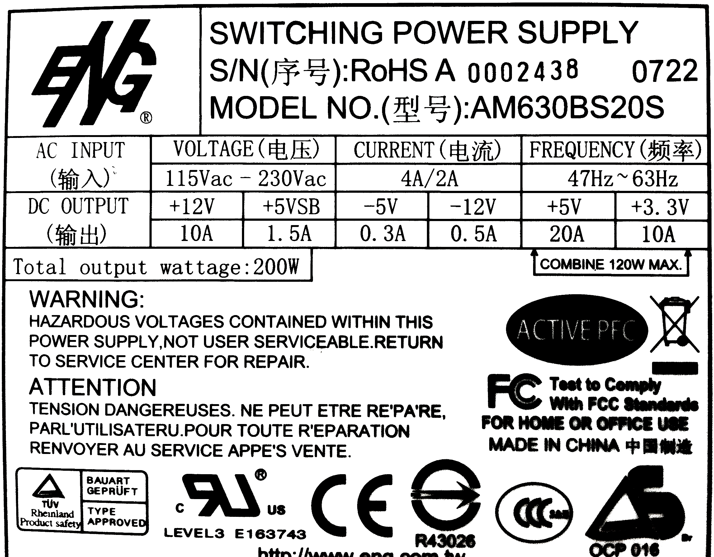
 |
| Output Voltage
|
Min Load+ |
Max Load |
| +5V |
2.0A |
20A |
| +12V |
0.1A |
10A |
|
-12V |
0.05A |
0.5A |
| -5V |
0.05A |
0.3A |
|
+3.3V |
0.2A |
10A |
|
+5Vsb |
0.0A |
1.5A |
|
Dimensions : 150mm x 86mm x 43mm (L x W
x H) |
|
 |
|
As well
as the maximum load values, although they tend not
to be shown on the data-plate, switched mode power
supply specifications typically quote values for the
minimum load required on one or more of the voltage
outputs. Operation of the PSU below the minimum load
values can result in unpredictable operation,
including poor voltage regulation and PSU shutdown,
although PC/ATX PSUs seem to be pretty forgiving and
actual damage to the PSU should not result. (SL
Power Electronics have a very brief explanation
of the issue in this
Application Note)
For
initial testing of the replacement PSU, I was not
too worried about the minimum load values, the PSU
would either work or not and I would have addressed
the load issue if the PSU did not run reliably. With
the DDFS connected, the current draw should be
sufficient to provide the minimum loads for +5V,
+12V and -5V, I didn't think that the -12V was too
much of a problem, but, depending on the stability
of the PSU, I may add a dummy load to the +3.3V line
at some point. (A R15 resistor fitted across the
3.3V rail would provide a load of 0.22A equivalent
to ~0.7W.)
|
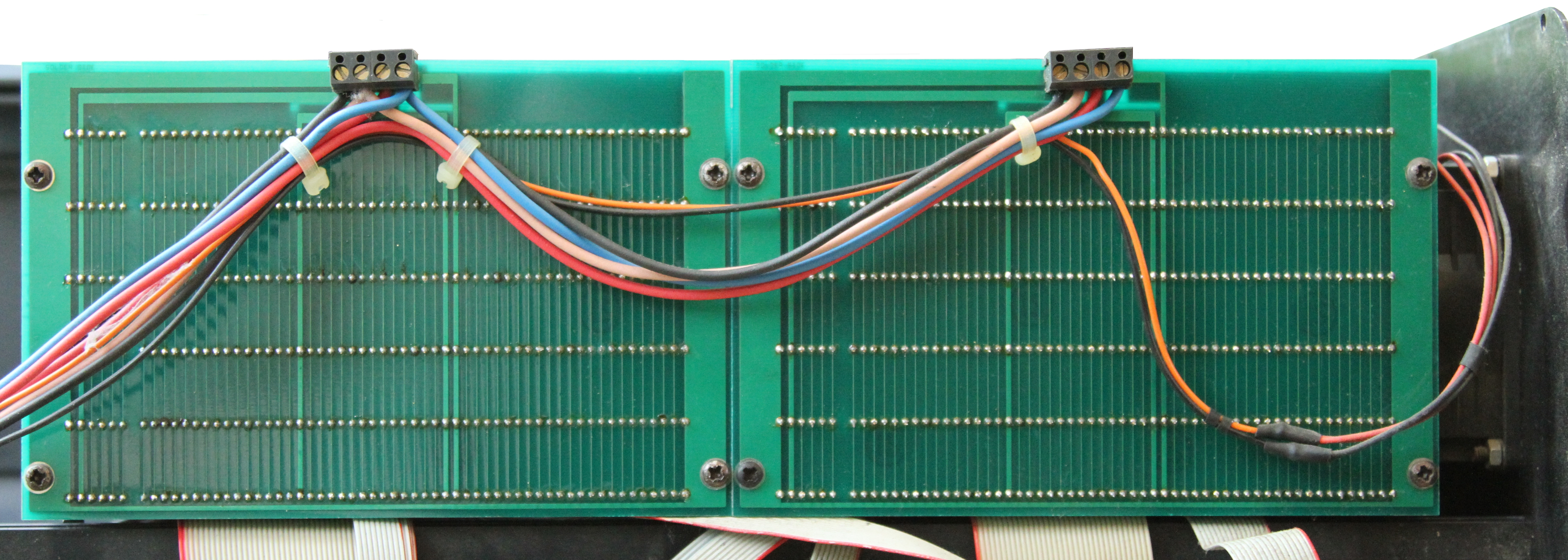
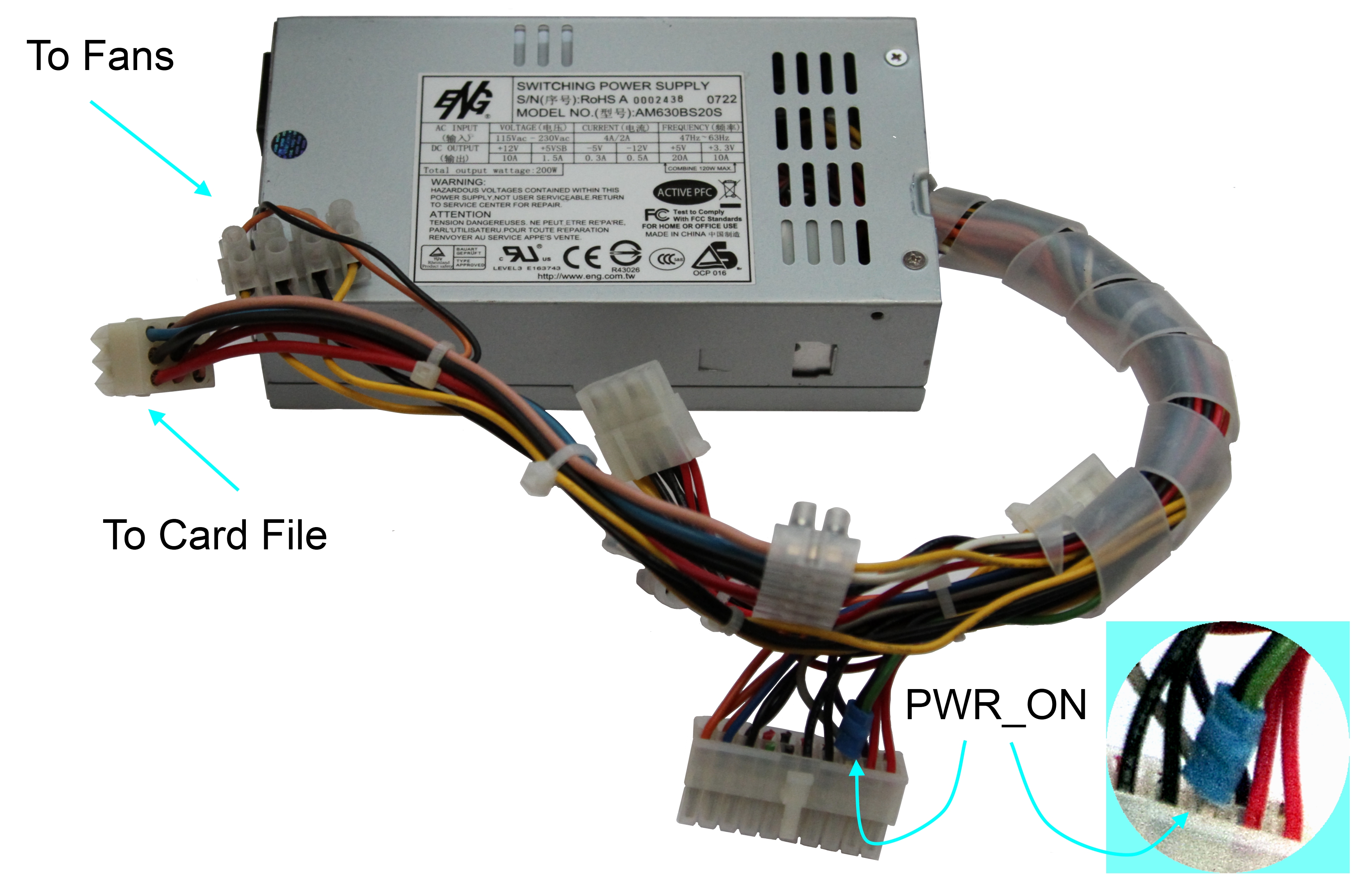
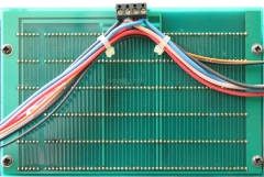
| Original power distribution wiring
for the DDFS. The two card cages have separate +5V
and common feeds from the PSU and daisy-chained +12V
and -5V lines. The case fans are powered by a
separate +12V line. |
 |
A close up of the rear of one of the
card cages, the lighter gauge wires are the +12V
supply to the case ventilation fans. The wires to
the card cages follow the same colour code as the
FDX :-
| +5V |
Red |
| -5V |
Blue |
| +12V |
Pink |
| Common |
Black |
|
 |
| Rather than doing a
similar "professional" upgrade as I did when I
replaced the PSU in my FDX, I decided to minimise the
modifications required to the DDFS, at least, until
I proved that it worked.
|
|
I removed the
PS_ON wire (green) and
a common (black) wire from the 20-way connector and
spliced them together so that the PSU would turn on when power was
applied to the IEC mains connector.
I removed the
eyelet connectors from the DDFS power harness,
retaining the existing multi-way plug & socket and made
connections to the PSU +5V, +12V, -5V and common
lines.
|
 |
| For initial testing, I connected an IEC mains
lead directly to the PSU, bypassing the DDFS power
switch and applied the power. The DDFS case fans
both started as soon as power was applied and it was
immediately obvious that in the long term I would
need to look at installing low noise fans! With
the fans working and the +5V, -5V and +12V voltages
checked, I temporarily "mounted" the PSU in the DDFS
and refitted the end-plate and covers, ready for
testing as a Video Wall ! |
|