|
 |
The Memotech MTX Series |
 |
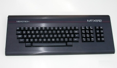
Memotech MTX
Keyboard Problems
This page provides some generic tips for fault finding of MTX keyboard
problems as well as a specific example courtesy of Ramon Merchan Sanzano.
|
MTX Keyboard -
Basic faults |
|
For an
overview of construction and normal operation of the
Memotech MTX keyboard, see my
keyboard page. |
 |
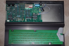
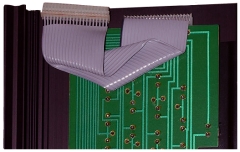
| The system board is fixed to the bottom of the
case and the keyboard PCB is fixed to a steel plate
mounted on the underside of the top of the case.
The grey ribbon cable connects the keyboard PCB
to the main board by plugging into the "J1"
connector above the edge connector on the left hand
side of the main board. Photo courtesy of John
Hancock |
 |
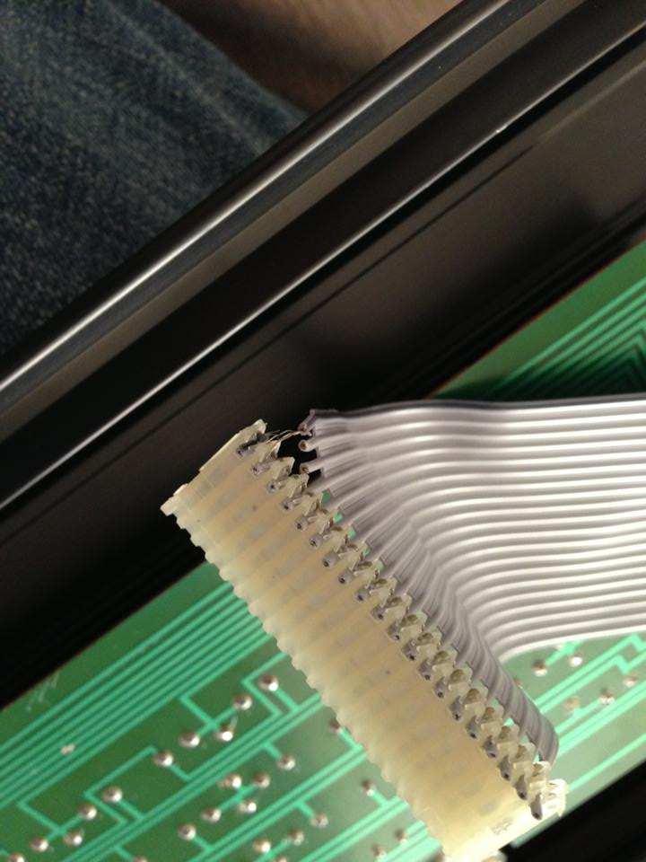
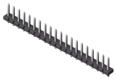
| "J1" on the computer is the 20-way SIL header located in the upper left
of the board. A similar SIL header is fitted to
the edge of the keyboard PC, and the two are
connected by the grey ribbon cable shown below. |
 |
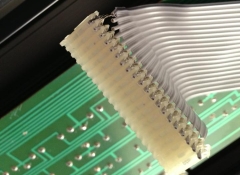
| As you can see in the photo, the ribbon cable is
somewhat unusual - unlike a more typical
IDC cable, the ribbon is not supported by the
connectors, instead, each core is stripped out from
the ribbon 5-10mm from the connector.
There is no strain relief on the cable and as a
result, the the most common "keyboard" faults are
associated with breakage of one or more of the
conductors.
Photo courtesy of John Hancock |
 |
|
Cable /
Connector |
| The photo shows the type of cable damage that
can result if the keyboard has been subjected to a
number of disconnections and reconnections or the
cable has been overextended when opening the case,
although it is more usual to see a single broken
core. Photo courtesy of Andy Garton |
 |
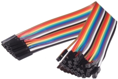
| I have used this type of cable to replace the
original cable in one of my MTXs, they are available
off ebay UK and cost around £1-£2, including
shipping from China - search for "DuPont cable".
The connectors are not fixed together into a single
plug like a normal IDC connector and the cable is a
little stiffer than the original, but neither of
these issues caused me any problems. |
 |
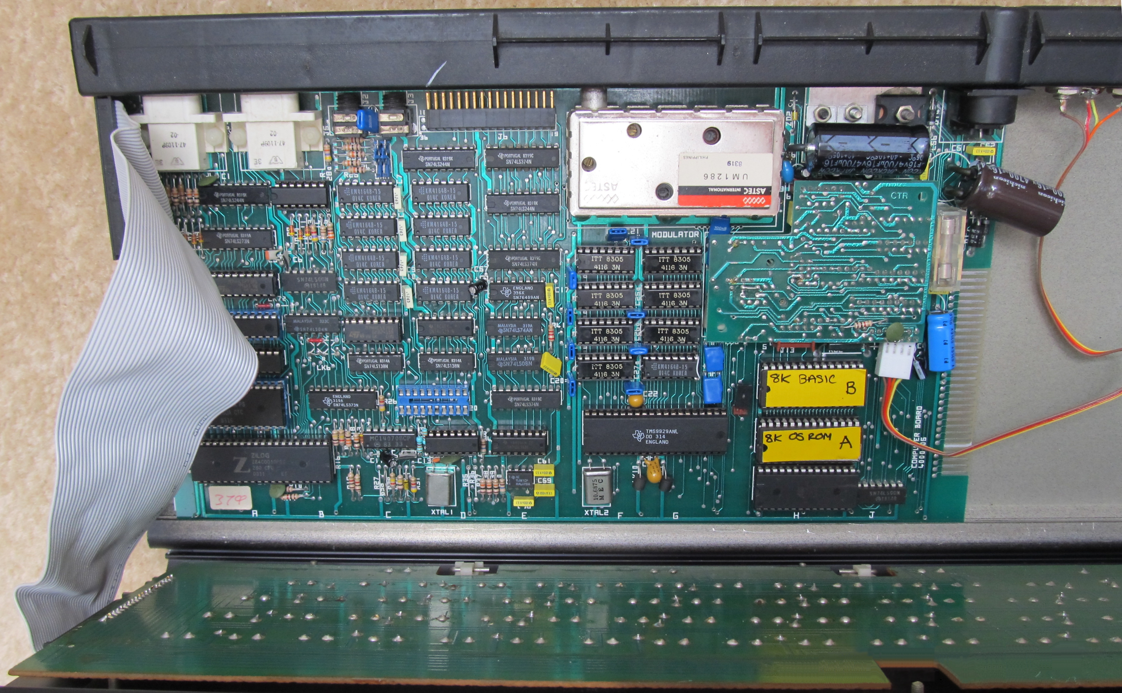
| Martin Allcorn's solution -
using an IDE cable, as the MTX only uses 20 pins for
the keyboard connector, only one row of the IDE
plug terminals and 20 cores in the IDE cable are actually
used. The photo also shows a 4164 DRAM being used
to
replace a faulty VRAM, the 8 x
4164 DRAM
installed in sockets in place of the original
32K of RAM, and a replacement cable for the
Video/Audio outputs (they also prone to breaking). |
 |
|
Key-switch
Operation |
| The MTX keyboard is a passive device, consisting
of 79 individual SPST key-switches. It is relatively
easy to check the function of the individual
key-switches using a multi-meter and checking that
the contacts close when the key is pressed.
With the keyboard inverted, it is also easy to
see whether there is any mechanical damage to the
PCB. |
 |
|
Key-switch
Repair / Replacement |
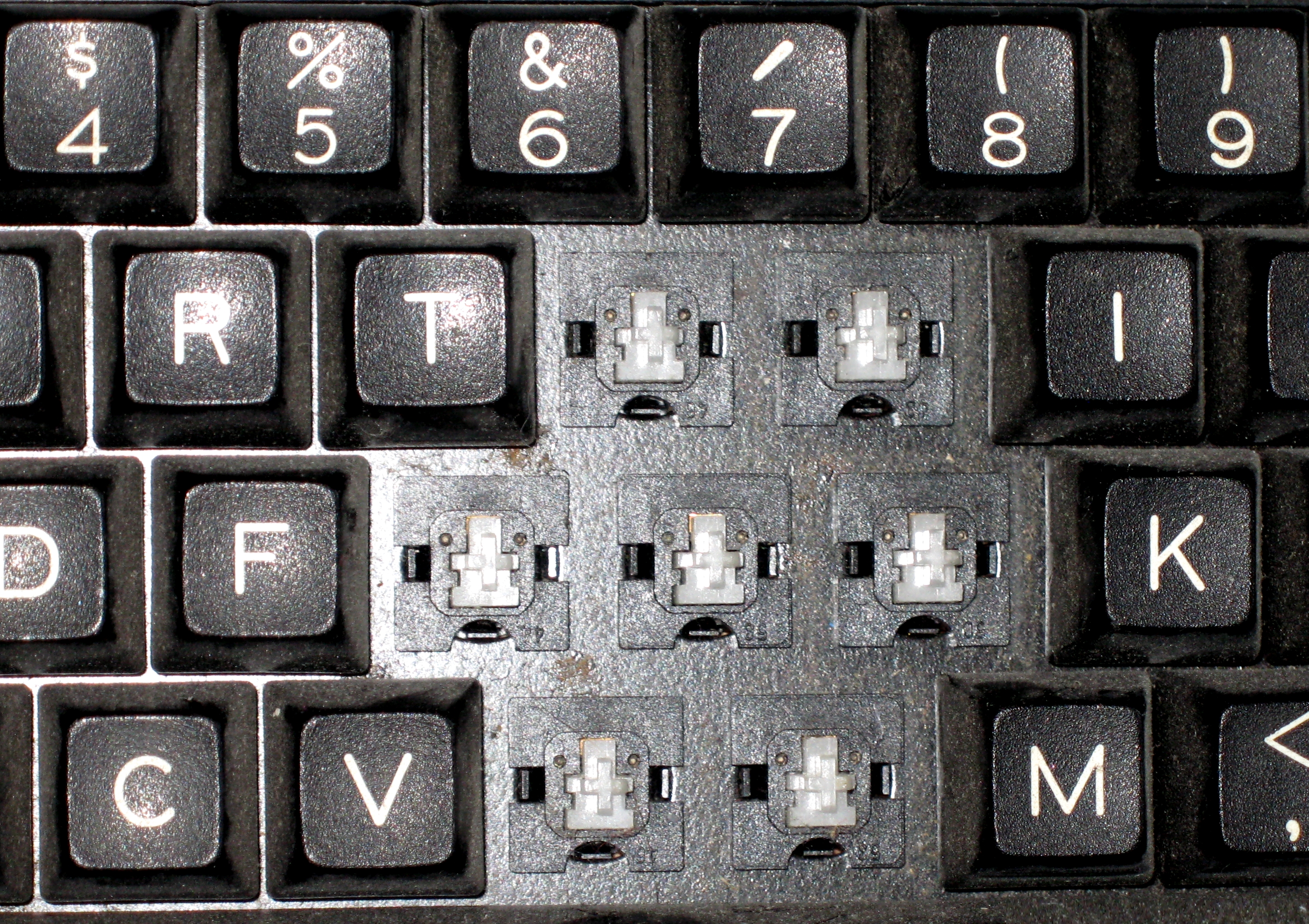
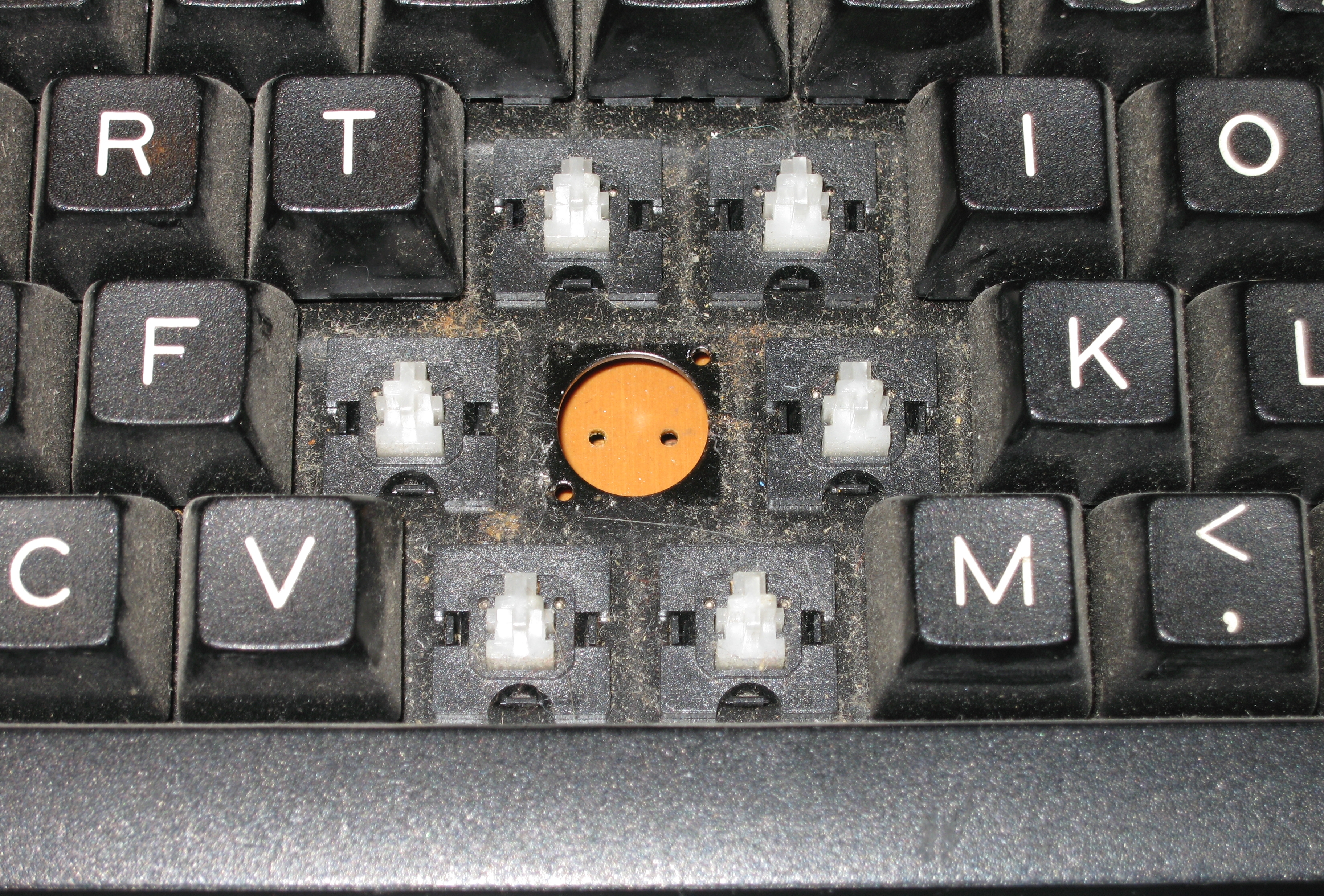
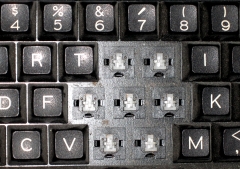
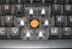
| The key-switches used in the MTX
keyboard are the same as those used for the Acorn
Electron and BBC Master computers. The switches
can be replaced without completely disassembling the
keyboard, but it is much easier if the surrounding
keycaps are removed first, in this photo, the
keycaps for the faulty "H" key and the keys surrounding it have
been removed. |
 |
It's a good idea to double check and mark the
position of the key that you want to remove before
you start !
De-solder the faulty key-switch,
using a solder sucker to ensure that the pins are
completely clear of the surrounding solder pad.
NB: It is VERY easy to lift the
copper trace from the substrate - be careful !! With the switch de-soldered, it can be lifted off
the PCB. |
 |
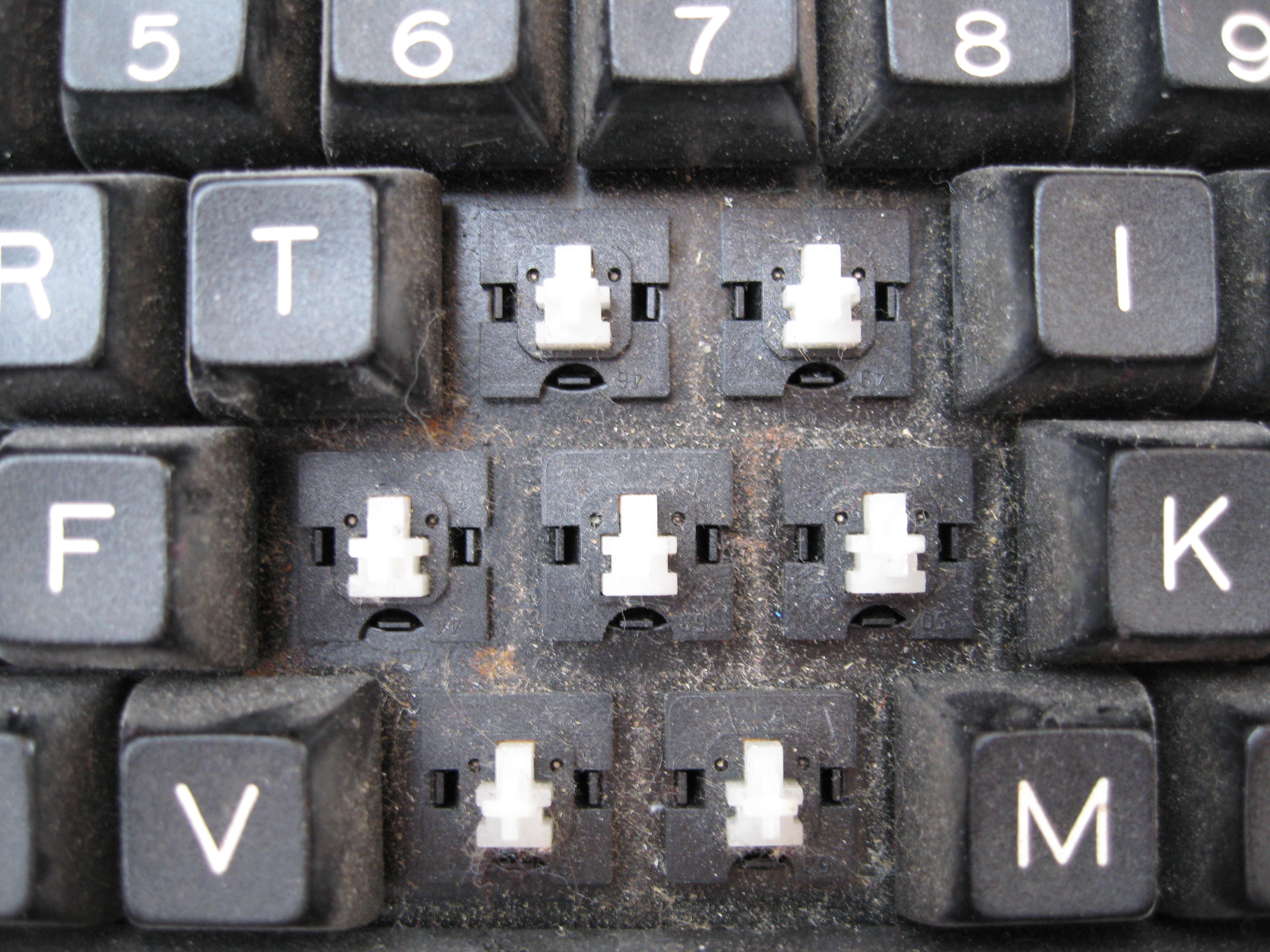
| The switches are held in place by
three plastic securing lugs located at the sides and
bottom. Use a small flat-bladed screwdriver to
gently apply some upward pressure to the switch
while you release the securing lugs.
If you intend trying to repair, rather than
replace, the switch, take care not to break of the
plastic lugs.
Some good photos of this step on a
BBC Master are shown on the
classic acorn site |
 |
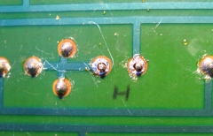
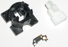
| Switch removed, the top side of the
PCB is visible through the resulting hole. Whether
you decide to replace the switch or attempt to
repair it will obviously depend on whether you have access to
replacement switches. I don't think that you are
likely to find new replacements, but keys recovered from
the Acorn computers mentioned may be available from ebay. |
 |
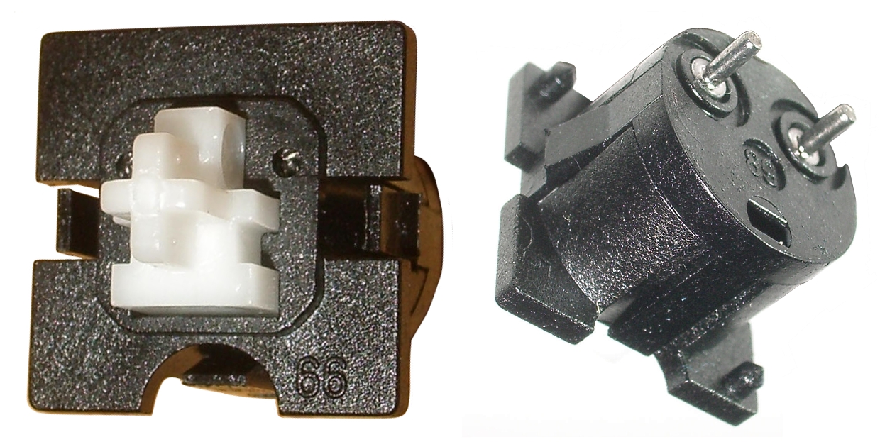
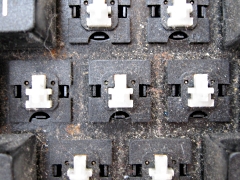
| I wasn't able to get very good photos of the key
switches, these excellent close-ups are from the
Deskthority wiki.
The key switches were made by Futaba and are the
low-profile linear type, the Deskthority wiki
has a
dedicated page
about these switches that gives clear instructions
for disassembly/assembly. |
 |
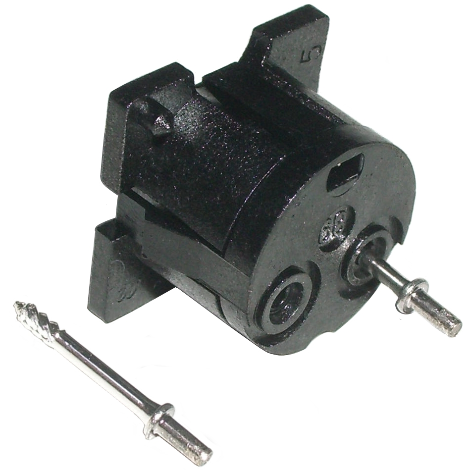
| The threaded pins are removed by
unscrewing them ~2 turns anti-clockwise.
The MTX keys just "snap fit" together, secured by
three retaining tabs, the two halves can be split by
gently prising them apart whilst levering the
retaining tabs out of the way.
(I believe some Futaba keys of this type may be
glued together, so it may not be possible to split
them without damaging them.) |
 |
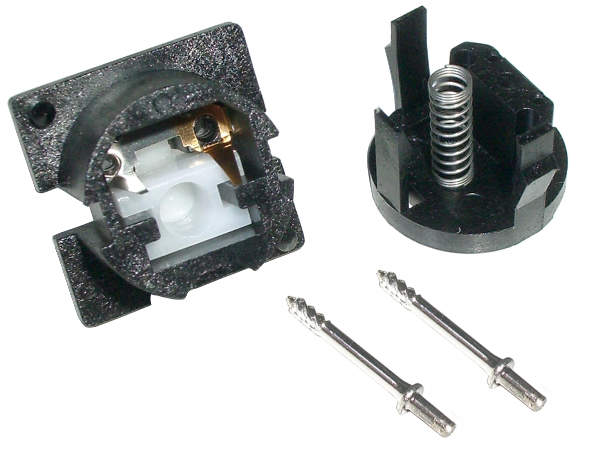
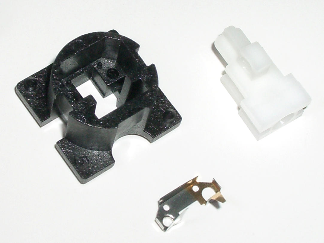
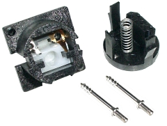
| With the switch split,
the component parts can be seen : |
| |
| Top half of
the switch |
the plastic plunger
(white) |
|
|
the leaf contact
(silver/gold coloured) |
| Bottom half
of the switch |
showing the spring |
|
 |
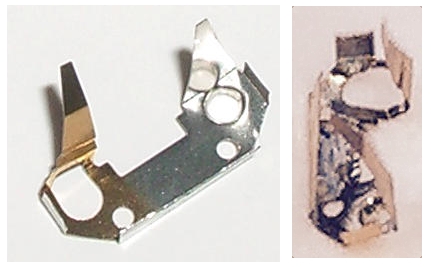
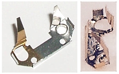
| Top half of the switch completely
disassembled, the leaf spring contact is very
fragile and unless damaged, it is probably best not
to try and remove it, if necessary though, it should
push out when the slider is pressed. If the
contact looks undamaged, cleaning the pins may be
all that is required to give the key switch a new
lease of life. |
 |
| The image on the right is a not very
good picture of the contact from the switch being
removed from the MTX above, as you can hopefully
see, it is pretty mangled. Although it may have been
possible to straighten and refit it, I didn't want
to take the chance and bought a "for spares" Acorn
Electron off ebay and replaced the faulty switch
with a known (tested) good one from the Electron.
This means that I also have quite a few good
switches that I can use to replace keys on other
faulty MTX keyboards. |
 |
|
Keyboard Fault Finding |
| If the fault is not a mechanical one
such as those described above, fault finding is a
little more involved, but not too difficult. Ramon
Merchan Sanzano had a fault with his MTX keyboard
with a number of keys ("W", "R", "Y, "I", "P") not working.
Ramon managed to fault-find the problem and put a
very
helpful post on the Memotech forum, he has
kindly allowed me to include some of the details here too. Most of the
content in this section is Ramon's but I have made a few changes,
mainly to aid readability. |
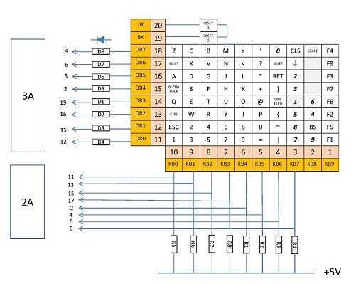
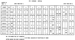
| As described on my
keyboard page, the MTX keyboard is essentially a
10 x 8 matrix of keys, the status of which are read
using Z80 IN and OUT instructions to the assigned
MTX I/O ports. Diagram reproduced from "The
Source", by Keith Hook, 1987 |
 |
| The computer board schematic in the Operator's
Manual shows the keyboard drive and sense lines, but
there is not a good description of the keyboard
operation in the manual and "The Source"
is, or at least was, not commonly available. Ramon
did his own analysis and came up with this keyboard
map and schematic diagram of the MTX logic circuits. |
 |
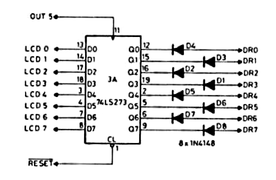
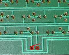
| It can be seen that all of the affected keys are
associated with the "DR2" drive line
which is on "J1" Pin 13, connected through diode
"D2" to the 74LS273 Octal "D" type flip-flop (board
position 3A). Diode "D2" and the resistors
were checked with a multi-meter and found to be OK. |
 |
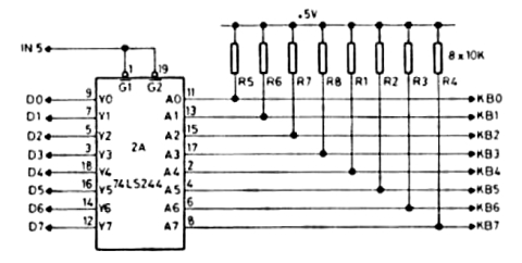
| All of the affected keys are read through Input
Port 5 using the 74LS244 Octal Buffer/Line Driver
(board location 2A) but use different sense lines
indicating that the fault was likely to be in the
drive line circuit. Ramon replaced the 74LS273 (3A)
which did not cure the problem, indicating that the
problem was the data bus input to the "D2"
drive line flip-flop. |
 |
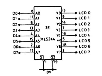
| A 74LS244 Octal Buffer/Line Driver (board
location 2E) is used to buffer the data bus lines
going to the majority of the physical output ports,
including the keyboard drive lines from Output port
5. Ramon replaced this component which fixed the
problem.
This fault would likely also have been evident had any
of the other output ports using data buffered by IC
2E been in use at the time. |
 |
| (The port control logic is performed
by the 74LS138 3-to-8 line decoders in board
positions 7C (IN) and 7D (OUT), which were operating
correctly since most of the OUT(5) and IN(5)/IN(6)
were picking up correct key strokes. |
|