|
 |
The Memotech MTX Series |
 |
Memotech Hardware Repairs
Update : subsequent to this repair, the same PSU developed another
problem, rather than attempt further repairs, I chose to replace the PSU with an
ATX PSU from a PC. Full details are on my
FDX PSU Replacement page.
Read on for details of replacing failed suppression
capacitors in the FDX PSU.
FDX Power Supply Repair
A word of caution: I not
an electrical engineer, the information on this page has come
from my analysis of the PSU in my FDX and reading of an Astec
Service Manual (which pre-dates the manufacturing date code of my
FDX power supply). This page is provided for "information only"
in the hope that it may be useful - however, it should not be
construed as a authoritative document on the FDX PSU or its
repair. You use it at your own risk
and if you are not competent to work with mains supply voltages,
which can kill you, leave it to
someone who is and put your equipment into an electrical repair
shop. [This probably applies to me too, but, anyway . . . . .]
This page describes how I repaired one "common" FDX PSU
problem, by common, I mean that of the very few FDXs that I know
of, this component has failed in at least two of them, and given
the nature of the problem, I am
surmising that it is common to all FDX PSUs. To
reiterate, this is the repair that I did on my FDX - not a
recommendation that others follow the same steps.
OK, with the disclaimer out of the way, here we go......
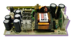
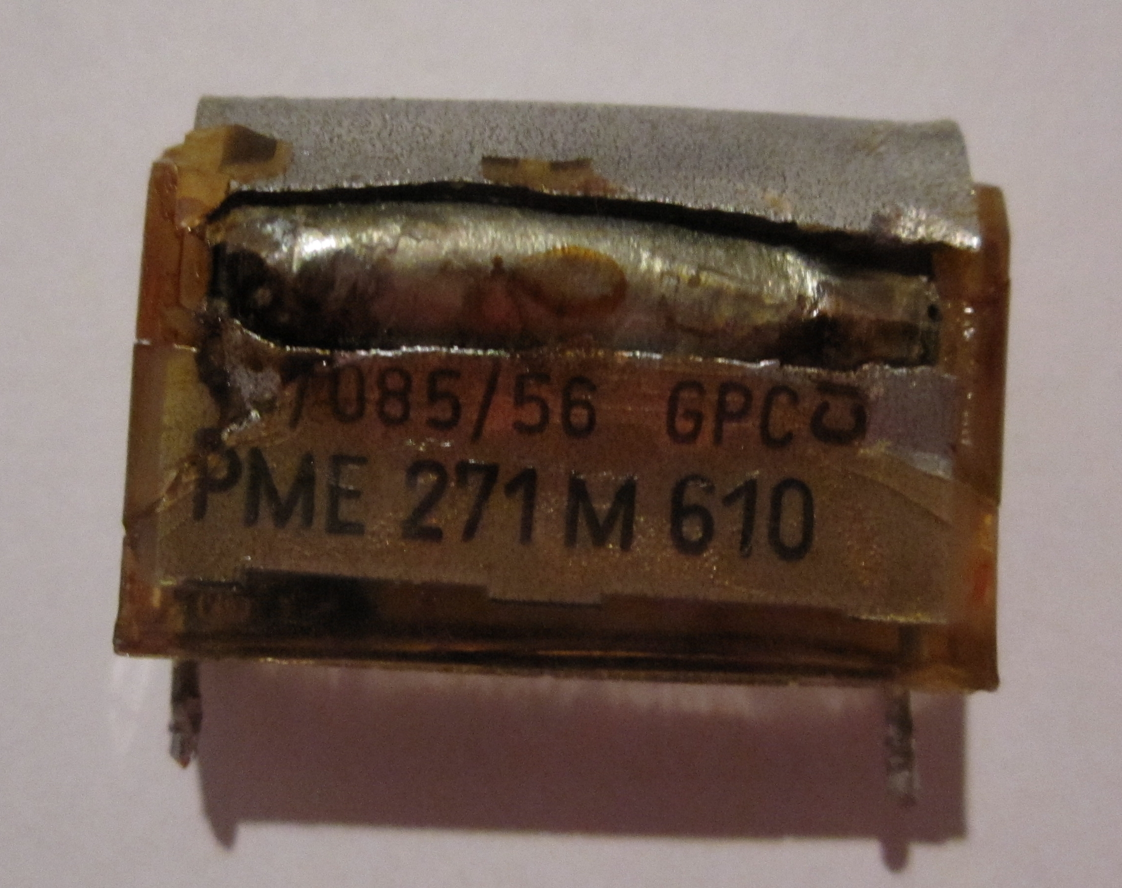
The PSU installed in my FDX is a Astec AC8251, it uses a Rifa MP (metalised
paper) line filter capacitor for EMI/RFI suppression on the
input side of the PSU, the component ID on the PSU schematic in
the Astec manual is
"C2" and is rated at 0.1 uF, 250VAC.
Metallised film capacitors can repair themselves to some
extent after a voltage spike but they degrade with age - and as
30 years is a long time, failure of this type and age of
capacitor is common in many types of equipment, including
radios, hi-fi systems, test equipment and computers. A common
problem with the BBC micro for example, is also failing power
supplies, caused by failure of the same type of capacitor - also
made by Rifa. Failures of Rifa MP capacitors is discussed in the
"Beware Rifa Class X Capacitors!" thread on the
vintage-radio.net site. One theory put forward as the cause
of the failure is that the epoxy case cracks due to age and/or
temperature and moisture is absorbed by the paper resulting in
corrosion of the zinc metalising which results in the capacitor
going bang! In any event, this thread confirms the high
incidence of failures of these components.
When these capacitors catastrophically fail, it is
pretty obvious, in my case, a cloud of white smoke and a
terrible smell resulted, this is pretty much the norm. Once the
system was switched off though, the smoke dispersed, the smell
abated and on powering up the system again, it appeared to be
working fine, and continued to do so. Since the most likely failure mode of this type of capacitor is for
it to fail open circuit, this would not
stop the PSU from working, but would result in reduced EMI/RFI
protection with unpredictable results on the FDX, the additional
electrical "noise" could cause various problems, but the
probability of their being any safety
issues is small.
This leads me to believe
that just because your FDX has no apparent problem, the
capacitor may have blown sometime previously and you may be
unaware of it - particularly if you are not the original owner
of the FDX. Even if the capacitor in your FDX PSU has not
failed, if it has not already been replaced, you should consider
doing so before its seemingly inevitable failure.
As well as their RFI suppression properties, these capacitors
in the Astec supply are "X" type capacitors, that
is, they also have a safety function. Safety
capacitors come in two types, "X" and "Y", type "X" are
placed between the "Live" and "Neutral" lines, i.e., "across the
line" and type "Y" are placed from "line to ground".
If a type "X" capacitor short circuits, there is
no increased
risk of electric shock, the risk is that self ignition of the
capacitor or an over current
situation that could result in a fire, although, in normal
circumstances, a protective fuse or circuit breaker would open.
If a type "Y" capacitor short circuits, there is an increased
risk of electric shock to the user. Since these types of
capacitors perform safety functions, they are tested and
certified by
independent safety agencies. The types are further divided into
classes, depending on their target application and therefore
required test voltage. Without detailing all of the classes, it
is sufficient to say that for the "across the line" capacitors
used in the FDX PSU, a type "X", Class "2" is required, i.e., an
X2 capacitor.
Strictly speaking, you must use a safety rated capacitor to
replace "C2". initially, as I had some difficulty in sourcing an "X" rated
replacement, and had been suggested a possible (non-X rated)
alternative, I was considering using a non-"X" rated capacitor made by a
reputable manufacturer, such as the Wima MKP-10. I decided
that this was not really acceptable but you will
need to decide for yourself if such a replacement is suitable
for your application, in any event, I did find that X2
capacitors were available on the ebay UK store, from a UK
vendor, so I used them.
Update: Mark Kinsey has pointed me to the Wima X2
capacitors on the Maplin website - I don't know why I couldn't find
them when I looked, but anyway, if I was doing this again,
these are the capacitors that I would use.
It is also worth noting that the same type of capacitor,
though smaller (0.01uF), is used in two other locations, at "C1"
and "C11". Given the difficulty in getting access to the FDX PSU
and the fact that these are the same capacitors that frequently
fail in the BBC Micro PSU, I chose to replace them at the same
time as replacing the failed "C2". If you were really keen to
minimise the risk of a future PSU failure, you should probably
replace the electrolytic capacitors too, but I have not done
this.
C2 Replacement
When "C2" is removed from the PCB, two pairs of mounting
holes are revealed, the existing capacitor had a 20mm hole pitch
but there were additional holes with a pitch of 15mm, connected
to the same tracks on the solder side. This was handy as the
replacement component that I wanted to use is slightly smaller
than the original and had a 15mm hole pitch.
C1 and C11 Replacement
The two smaller, 0.01uF "X" capacitors are located close to
the 2A, 20mm, fuse. Again, the PCB has two pairs of mounting
holes, with hole pitches of 15mm and 12mm. The replacement
capacitors that I obtained had a 15mm pitch, so fitted into the
same holes as the removed components.
|
FDX Power Supply |
|
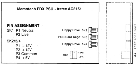
The FDX used an Astec AC8151-01
to provide power to the 6" PCB card frame and
the floppy disk drive(s).
There is a copy of
the Astec Specification and Repair Manuals on the
Manuals page
|
Specification Summary |
+5 VDC |
2.5 A |
|
Input Voltage 115 to 230 VAC |
+12 VDC |
2.0 A |
|
Input Current 0.85A (rms) |
-12 VDC |
0.1 A |
|
|
 |
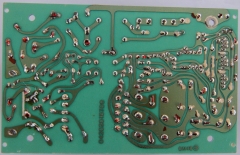
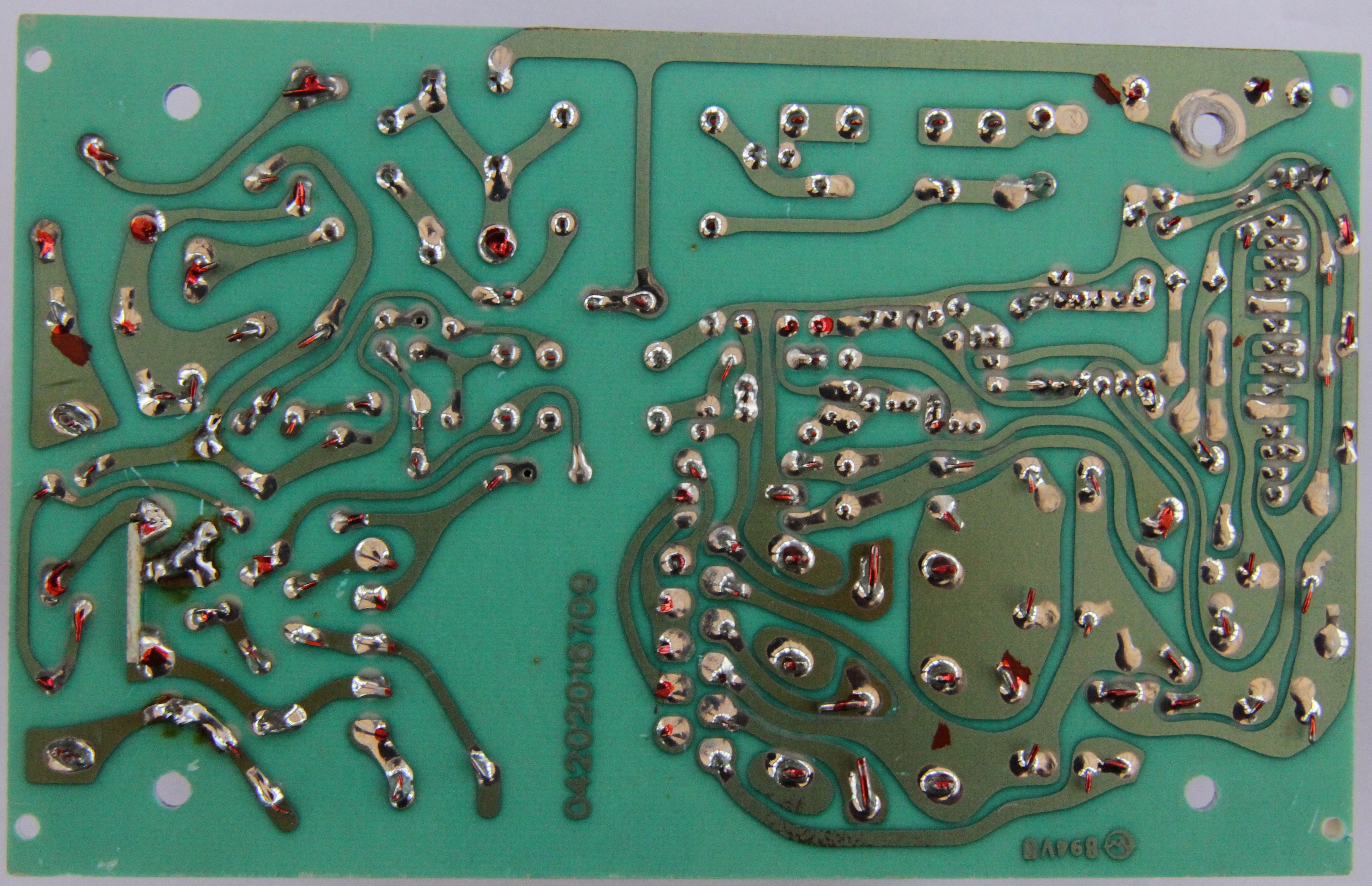
PSU board solder side |
|
|
|
|
C2, C1 and C11 Capacitor Replacement |
|
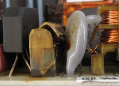
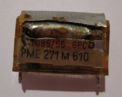
A close up of the failed 0.1uF, 240VAC capacitor,
C2, before it was removed from the PSU in my FDX. You
can see that the case has split, when this
happened, dense white smoke poured out of the
PSU and a film of brown material sprayed over
nearby components as you can see on the adjacent
component, C4. |
 |
|
A close up of the failed 0.1uF, 240VAC capacitor,
C2, removed from the PSU. You can see the case
has completely split and the internals are
protruding from it. |
 |
|
OK, the PSU has been removed, the shiny new
components ordered off ebay have arrived, a
quick check of the values and we should be good
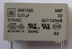
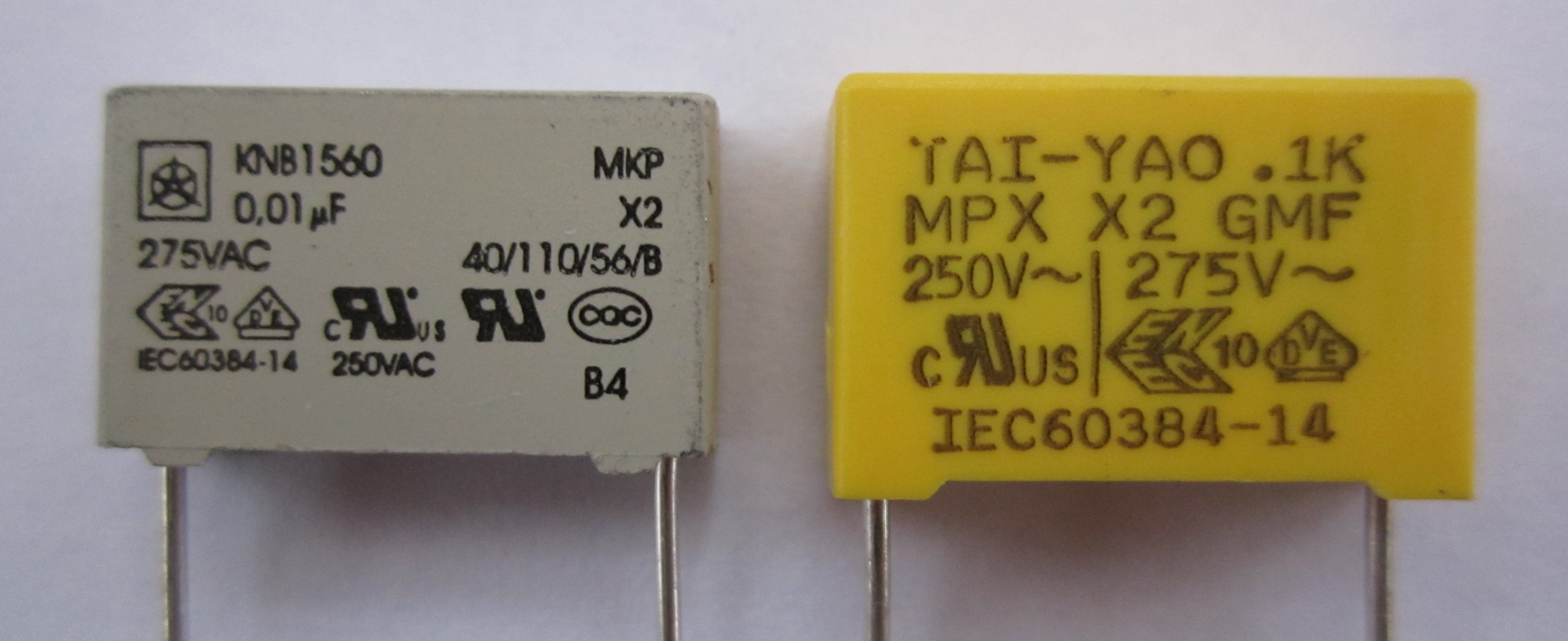
to go. 1. This is the replacement for C1 and
C11, a 0.01uF, 275VAC, X2 - that's
fine (Manufactured by Iskra, you can open the
component datasheet if
required) |
 |
|
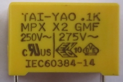
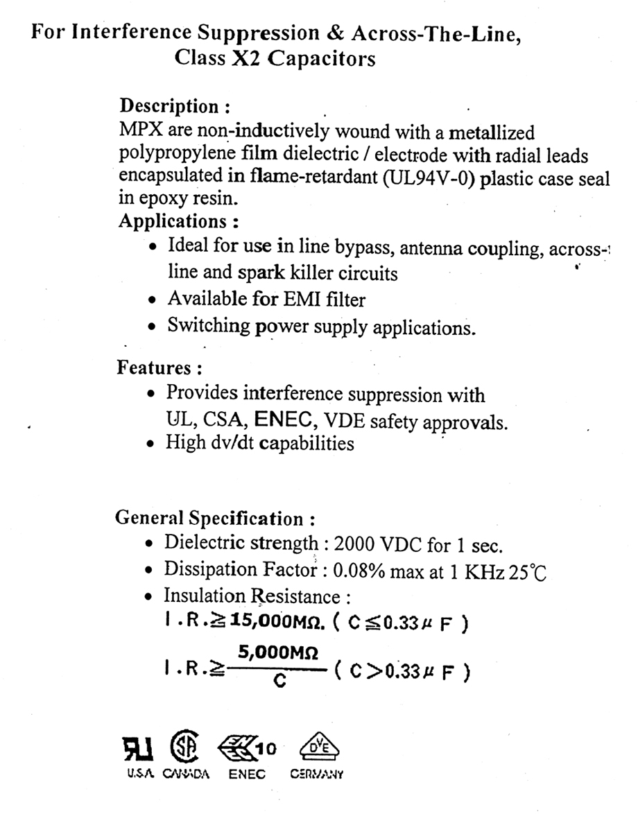
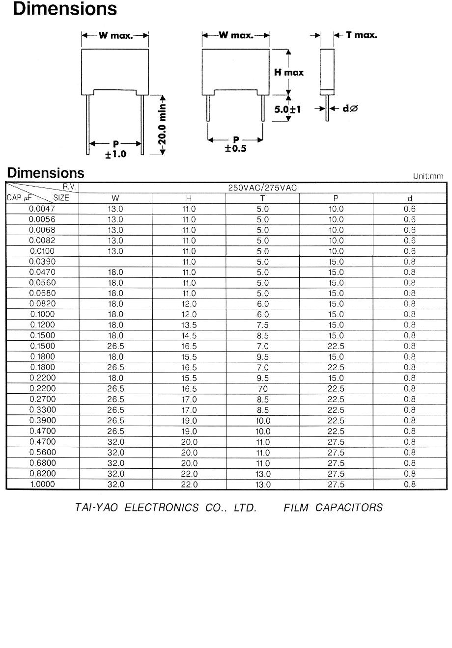
2. This is the replacement for C2, and should be
a 0.1uF, 240/275VAC, X2 . . .
Wait a minute -
what's a ".1K" capacitor?
In case you don't know (I didn't), as a
general rule, if the number is an integer
greater than 1, then the value is in pF, if it's
less than 1, the value is in uF. the "K" is not
a unit (kilo), it is the tolerance identifier,
"K" means +/- 10%.
So, despite the odd looking value marking,
this one is correct too: 0.1uF, 10%
(Manufactured by Tai-Yao, you can open component
datasheets here and
here.) |
 |
|
Replacement of any or all of these capacitors is a very easy
task, so much so, that there is very little point in describing
the operation in detail. The most time consuming part is having
to almost completely dismantle the FDX to be able to remove the
PSU. That part is common to just about every FDX repair job and
it worthy of its own page - for details on how to
disassemble and reassemble the FDX see
the guidelines here. Once you have removed the PSU from the FDX it is a simple
matter of de-soldering the old component and fitting the new. As
you can see from the photo of the solder side of the PSU PCB, it
is a much less difficult task than working on, say, the MTX
computer board. |
|


