|
 |
The Memotech MTX Series |
 |
Memotech Hardware Repairs

FDX Disassembly / Reassembly
Caution !
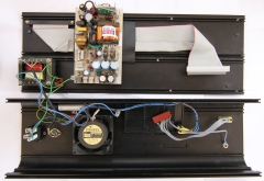
With the FDX open, and the rear panel swung
away from the end plates, the FDX power supply and the additional transformer
used to supply power to the MTX (if present) are revealed. These items have
exposed terminals which carry
mains voltages - take care when working
inside the FDX with the power on, also be aware that
the PSU capacitors can hold charge for a few seconds after the power is removed from
the system. The FDX is a nice looking unit, but was not made to be
"maintenance friendly" and does not have the modular
construction of a modern day PC. There are few, if any, internal
parts that can be tested or replaced without an almost complete
disassembly of the FDX. The notes here are based on
disassembly of my own FDX and photographs of others. Given
Memotech's penchant for "customisation", you may find that the
internals of your FDX are different from what you see here, but
they should be very similar.
Depending on the reason for opening up the FDX, you may, or
may not, want to test the system while it is in a state of
partial or even complete disassembly. It is more than likely
that you will though and you may want to connect and disconnect
the MTX keyboard at various times during the process. As you
will see later, once the FDX is even partially disassembled, it
can be difficult to get access to the interface connector on the
bottom of the case to connect or disconnect the ribbon cable. I
suggest that you leave the cable connected at the FDX and have
the MTX case open to expose the RS232/Bus Interface card and
make any connection or disconnection of the ribbon cable at the
MTX end as required. It is possible to connect the interface
cable onto the RS232/IF card with just the MTX right side end
plate off.
|
Disassembling the FDX |
| Power Off the FDX, and if using
a separate PSU for it, the MTX too. You can
always apply power later if required, but with
the exposed mains terminals and bits of bare
metalwork likely to be moving around, not to
mention your hands & fingers, this is an obvious
and essential safety step. |
| The FDX is held together is a
similar way to the MTX itself, with a number of
fixings, in this case "Phillips" head screws,
rather than hex-head used in the MTX, and
interlocking aluminium panels. The case is
made from two "U" shaped panels which form the
front and back, these are linked by flat plates,
forming the top and bottom and the case is
completed and held together by two flat end
plates secured with screws.
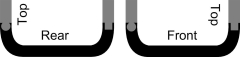
The front and back pieces have profiled
edges, one edge is a flat groove, the other, a
round channel like the front of the MTX case.
The flat edge can be pulled away from the edge
of its mating plate but the channel edge must be
slid all the away along its edge to separate it
from its mate, like the MTX keyboard.
As shown in this end on sketch, the front
panel has the round channel at the bottom and
the rear panel has it at the top. |
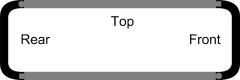
(not to scale)
 |
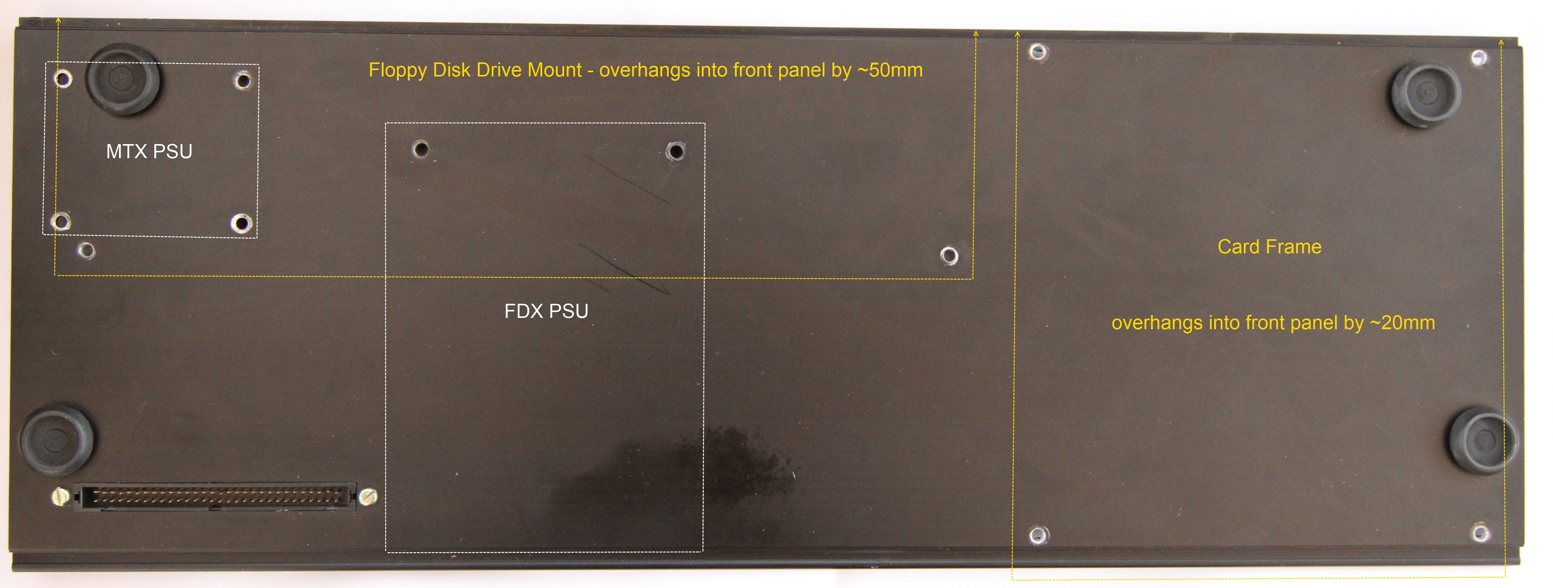
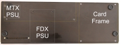
| There are a multitude of fixings
in the base, I thought it might be useful to
do a sketch showing the position of the major
components and their fixings. It is useful to
know where things are positioned before you make a start on
opening the case. This is one of my FDXs, but
you may find that yours is different, there
seems to be a bit of variation on how some of
the components were fixed to the case. |
 |
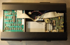
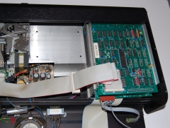
| With the FDX facing forwards,
remove the six Phillips screws from the left
hand end plate. The top panel can then be slid
out to the left, exposing the top of the 6" card
frame and the disk drive(s).
In this single drive model, you can see the
FDX PSU below and behind the silver plate where
the second floppy would sit in a twin disk
system. If the second disk was installed, you
would not be able to see the PSU at this point. |
 |
| Removal of the two Phillips
screws at the rear of the right hand side of the
case with allow the rear panel to be swung away
from the top of the case and lie flat on the fan
cover. Removal of the input and output power
leads will allow the panel to sit flat on the
bench. The edge of the rear panel fits into the
slot in the base panel, this is not profiled, so
can be pulled completely away from the base if
required.
At this point, the case body and rear panel
are linked by the power and earth wiring,
care is required to make sure that you don't
stress or break any of the interconnecting wires
as there is not much "slack" in the wiring. |
 |
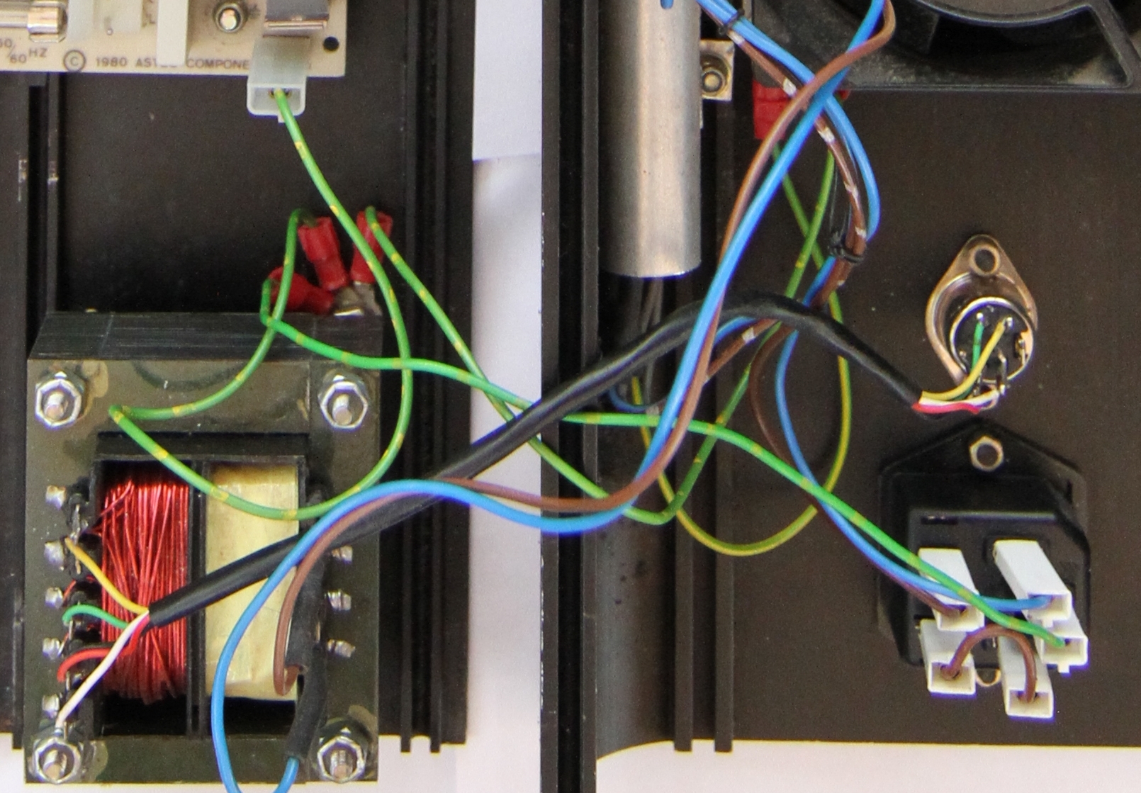
|
There is a small, 2-pin connector for the AC
input and an earth wire push-on connector that
connect the supply from the rear of the case to
the FDX PSU.
In the twin drive FDX, with an MTX power
transformer, the transformer will need to be
unbolted from the base to allow the parts to be
completely separated. Unless you are replacing
the transformer, this step should not be
required.
|
 |
|
With care, it is now possible to access the
6" card cage and remove the PCBs as required.
and access the drive electronics. However,
further disassembly is required before the
floppy disks or FDX PSU can be removed. In the
unlikely event that you want to remove the 6"
card frame, with the PCBs removed, you can get
access to the fastenings which secure the card
frame. On my FDX, this is done using four bolts
that pass through the base plate and are secured
with
nylock nuts on the bottom edges of the card
frame.. |
 |
| A recurring theme on my FDX
pages seems to be the maintenance "unfriendly"
nature of the construction - the floppy drive
mounting arrangement is no different. Access to the
drives to allow
them to be removed is a real pain, the case
needs to be almost completely dismantled before
the drives can be released.
The floppy drives sit on an aluminium plinth
and are secured from underneath, there is no
real way of removing a drive from the plinth
while it is still in the case.
It **may** be possible if you
have a mirror, have appropriate tools and are a
bit of a contortionist, but as you need to work
in close proximity to the PSU, there is a good
chance that you would damage it, so the best way
is to remove the drive plinth from the case. |
 |
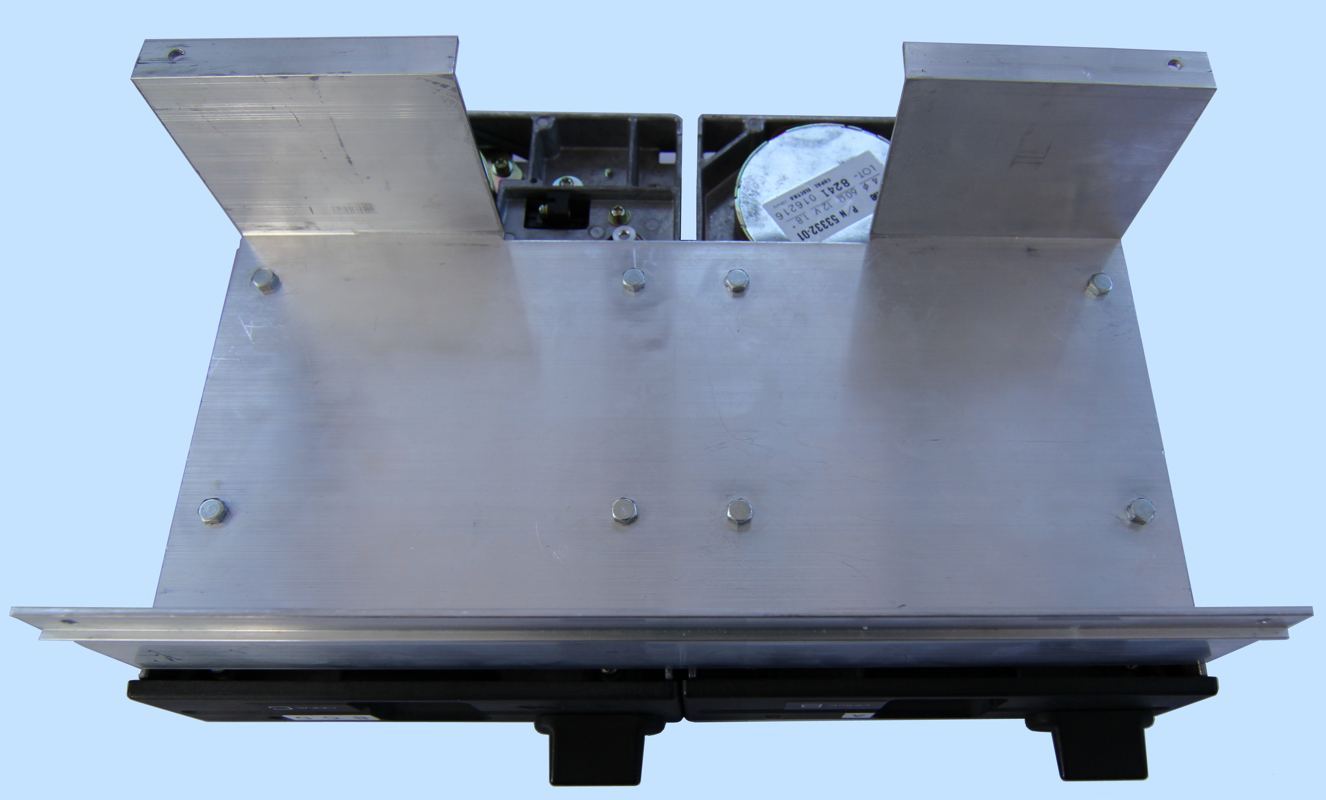
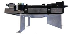
| A profile view of the plinth.
The two "feet" shown at the left hand side of
the photo straddle the PSU at the rear of the
case, each is fixed with a bolt through the case
bottom and secured with a
nylock nut. The front of the plinth is
supported by a ledge in the front panel and two smaller diameter bolts are
held captive in a channel in the front panel,
these bolts are also secured with
nylock nuts.
|
 |
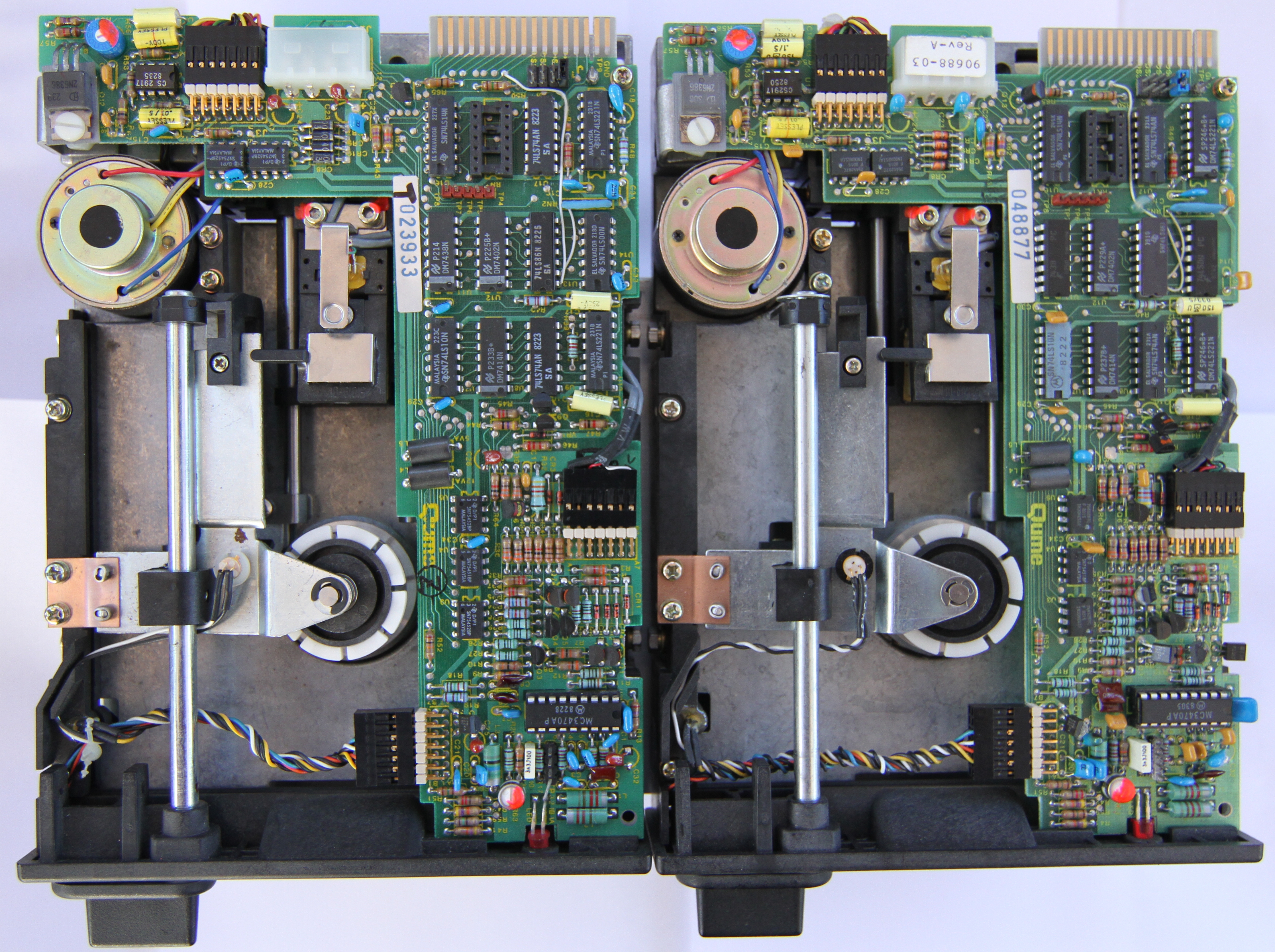
| This is a view of the underside
of the plinth. Each drive has four "L" shaped
brackets bolted to its sides, the bottom of the
brackets are tapped to mate with the bolts that
you can see on the underside of the plinth. |
 |
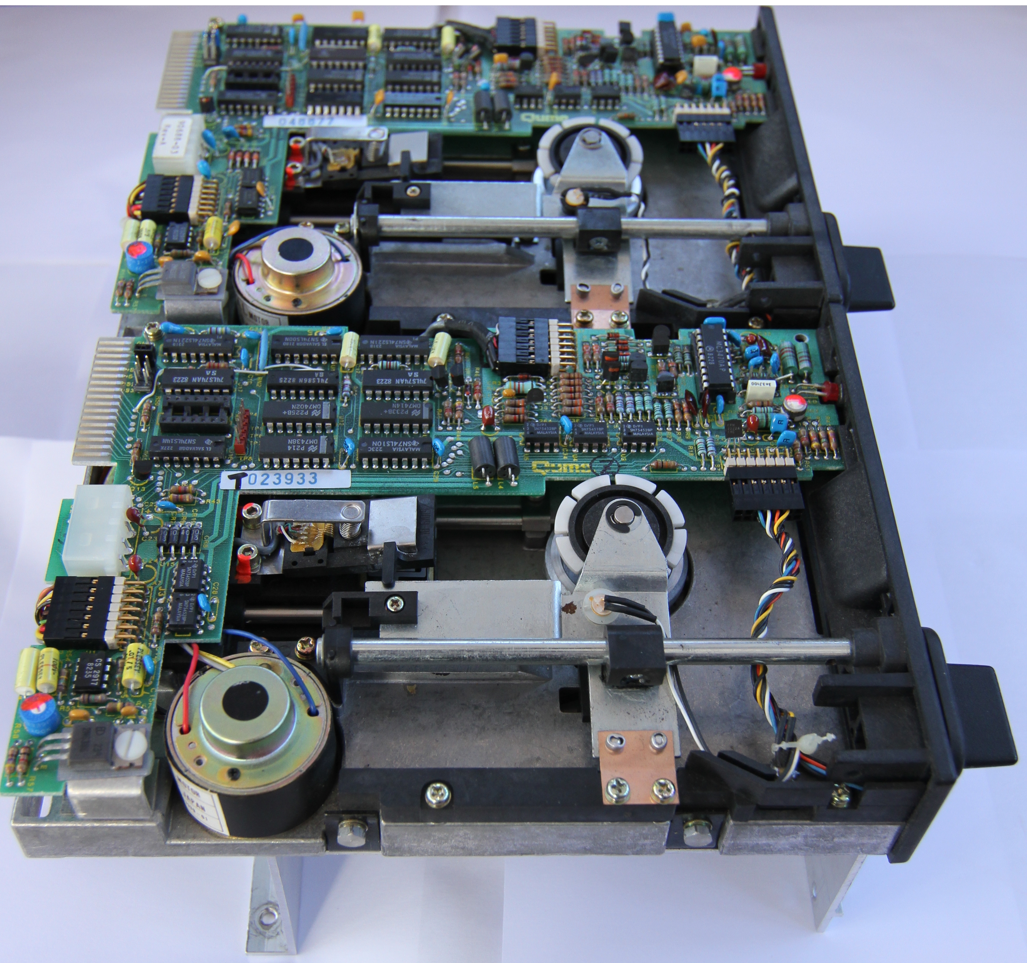
| In this overhead view, between
the two drives, you can see two of the bolts on
each drive that fix them to the angled brackets.
They were cunningly selected to be just too
long to allow them to be removed from above
without fouling on the opposite pair of bolts! |
 |
Remove the right hand end-plate
and disconnect
the floppy power and data cables. Remove the two
bolts that pass through the base and remove the
nylock nuts that hold the plinth to the
front panel.
The front panel can be tilted forward
slightly, hinged on the round profile mated with
the base, to make removing the drives a little
easier.
By tilting up the drive plinth it is possible
to slide it to the right until it clears the
case. Care must be taken not to catch the wiring
to the power switch on the front panel , the
power wires to the card cage, or the low voltage
AC wires from the MTX transformer. You need to
be careful not to damage the main PSU or the MTX
transformer as you slide out the plinth. |
 |
| |
|
Is it
probably not necessary to remove the front
panel, but if you want to do so, it is fairly
easy. The plastic trim is clipped into the cut
out on the front of the FDX. Working from the
front, slide you fingers behind the panel, in
front of the card cage. There are three plastic
clips on the top edge, working from the left,
gently push out each clip in turn until the top
edge clear the cut out. The bottom edge has a
groove in it. Lifting it slightly will allow it
to be removed. The easiest way to detach the
trim from the front panel is to put it back
inside the case, this can be done by angling it
as required. The front panel can now be slide
to the right until it clears the base plate |
|
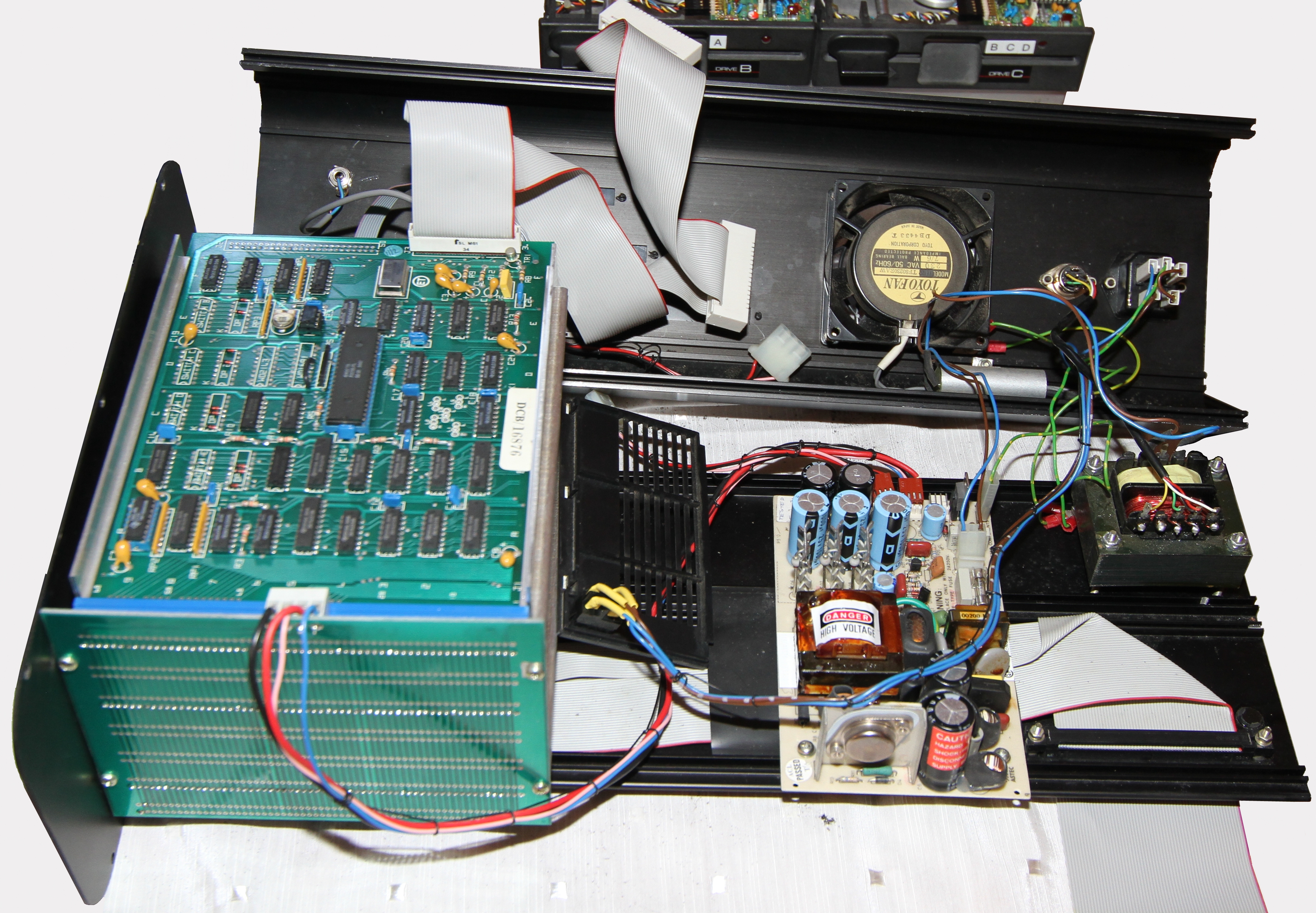
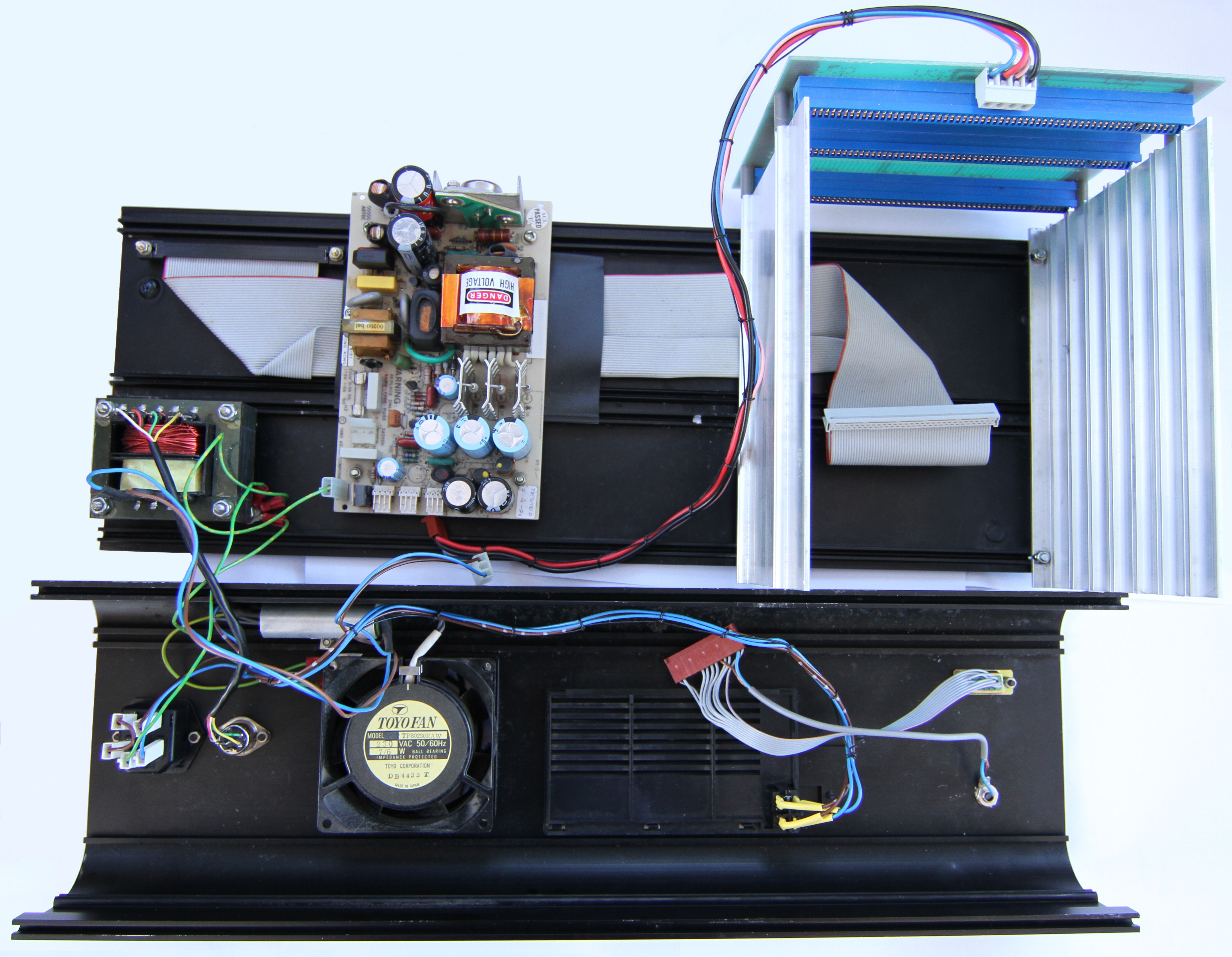
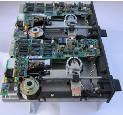
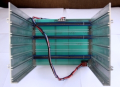
| Front view, showing the card
cage, the main FDX PSU and the MTX PSU. The
fan exhaust grill and power switch panel is
lying adjacent to the PSU and are still attached
to the AC input wiring on the rear of the case.
(If you want to completely separate the base and
rear panels, the MTX transformer can be removed
from the base.) |
 |
|
There are probably few occasions where you will
want to remove the card cage, but it is easily
done. On my FDX, four bolts, secured with
nylock nuts, fix the card cage to the base
of the case. As you can see from the photo, it
is not necessary to remove the card cage in
order to remove the PSU. |
 |
|
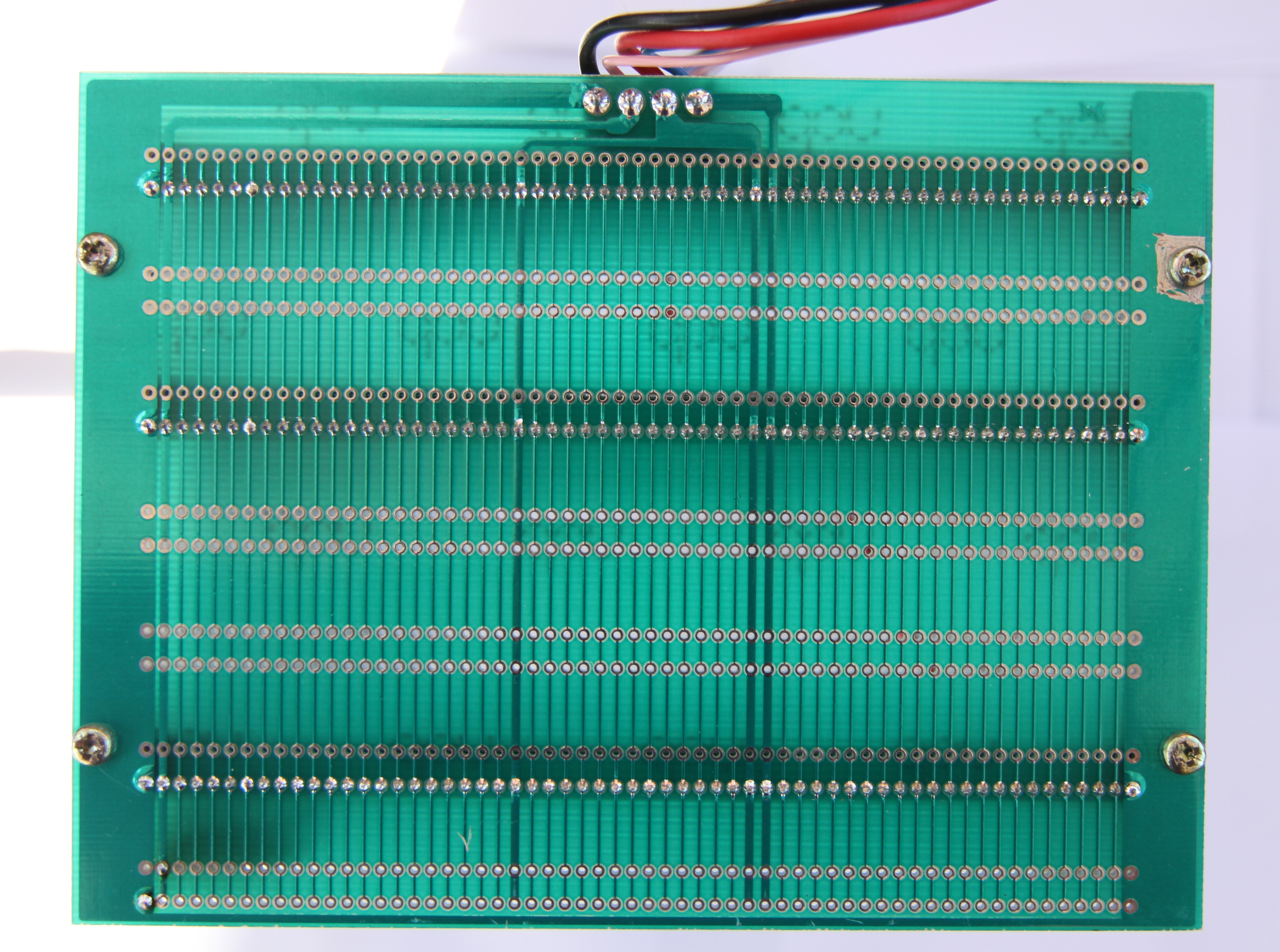
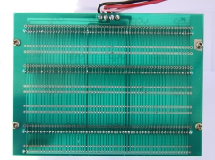
Rear view of the 6" card cage, showing the shadow
of the three PCB connectors fitted and the
available slots for additional PCBs - originally
intended for the Silicon Disk cards. When
viewed from this side, the connections from the
FDX PSU are, from left to right : Common
(black), +12VDC (pink), +5VDC (red) and -12VDC
(blue).
The rear of the card cage is positioned just
inside the front, left hand cover, behind the
fan exhaust grill and power switch panel. |
 |
|
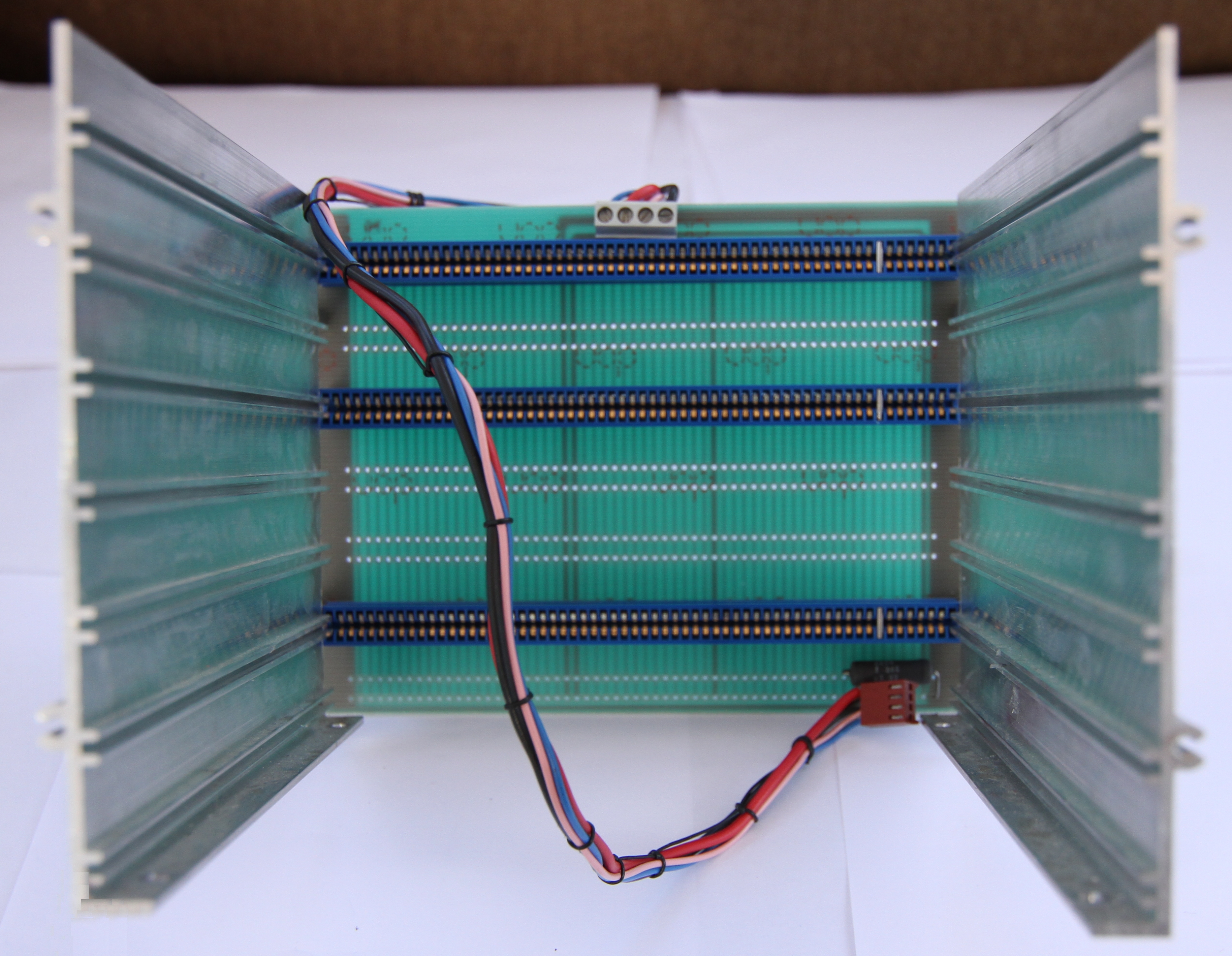
Front view of the card cage, showing the three
PCB connectors and the power lead to the FDX
PSU (unplugged). When
viewed from this side, the connections from the
FDX PSU are, from left to right : -12VDC (blue),
+5VDC (red), +12VDC (pink) and Common (black).
In the bottom right hand corner, there is a
large power resistor between +12VDC and ground,
I think this must be to make sure that the PSU
12VDC current is above the minimum shown in the
specifications. (Only 1 of my FDXs has
this.) |
 |
|
On my FDX, the main power supply is fixed to the base with
two self-tapping screws that fit into the metal
channel close to the front edge of the base
plate (at the top of this photo) and two bolts fixed through the
base. Other FDXs I have seen use four bolts that
are fixed through the base plate rather then the
self-tapping screws. All fixings have insulating spacers
fitted and the bolts are secured with
nylock nuts. A protective earth wire is fixed to the
corner of the PSU with a push-on connector. |
 |
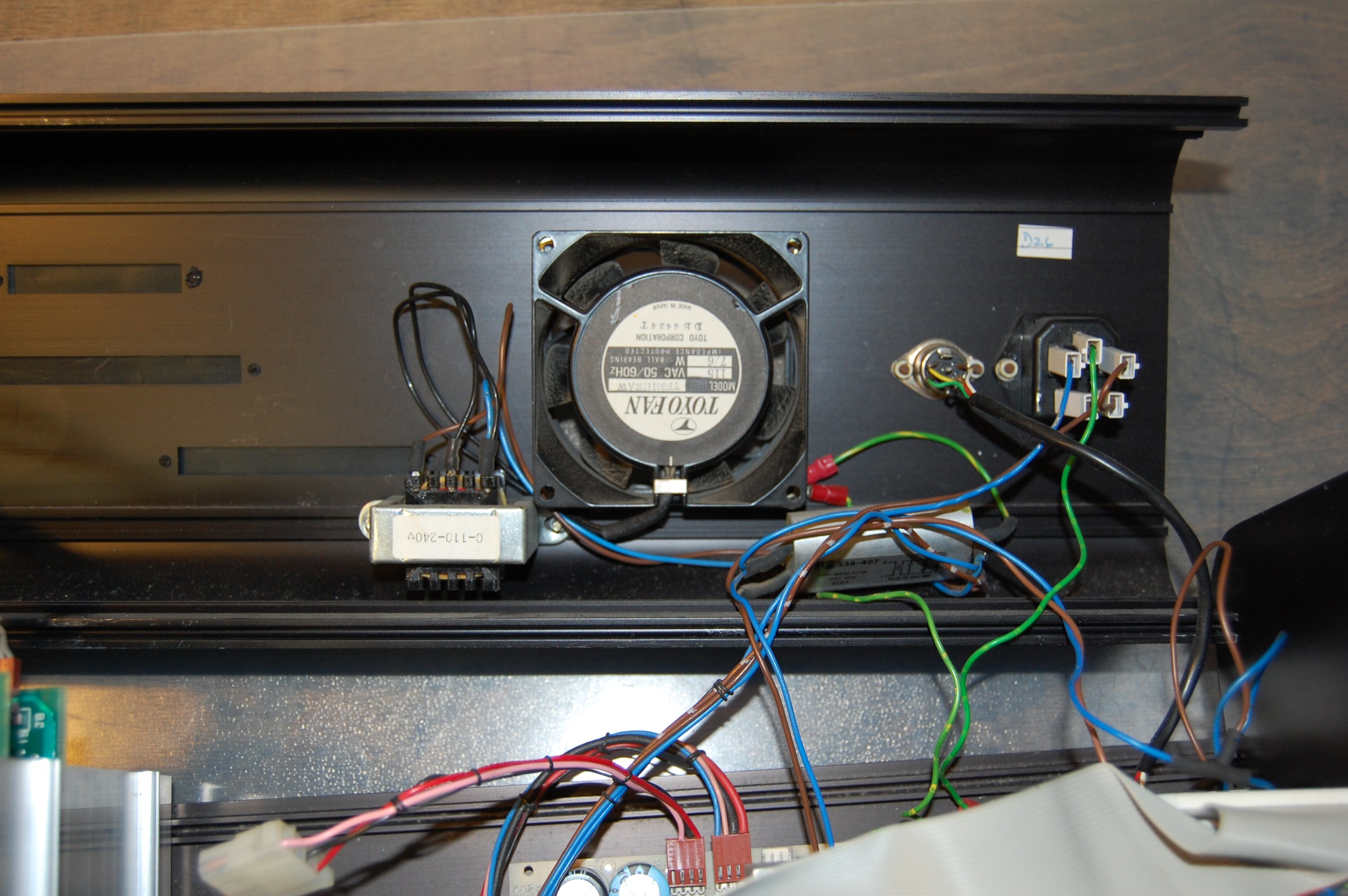
|
The remaining component fixed to the base plate
is the transformer used to supply low voltage AC
to the MTX from a double drive FDX - it is not
fitted to the single drive version.. This is the
same transformer that is used in the MTX desktop
PSU, without any protective cover - the primary
and secondary winding taps are exposed - you
need to be aware of this if working on the FDX
under power. Similarly, the mains input and
connections to the fan may also have exposed
terminals. |
 |
|
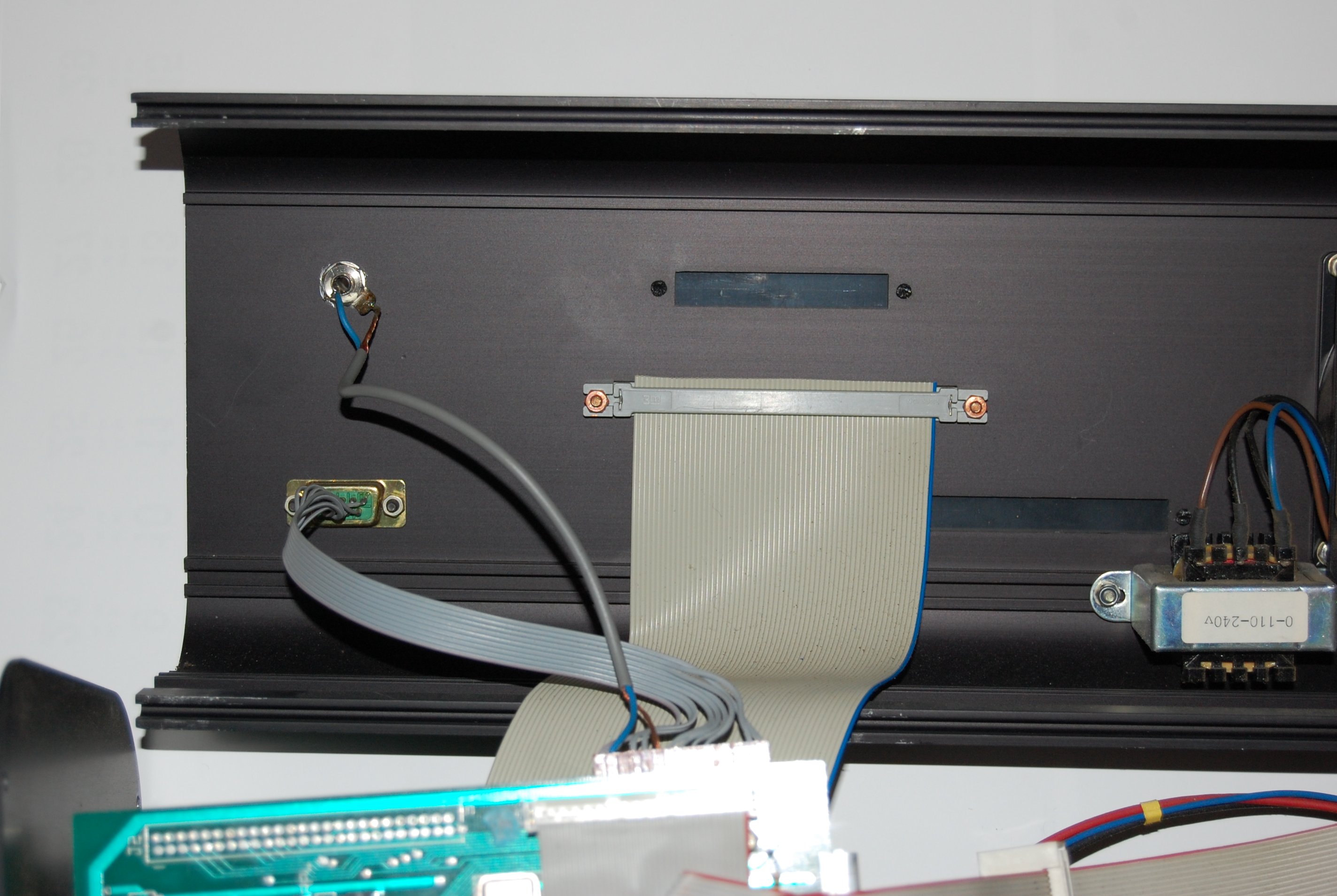
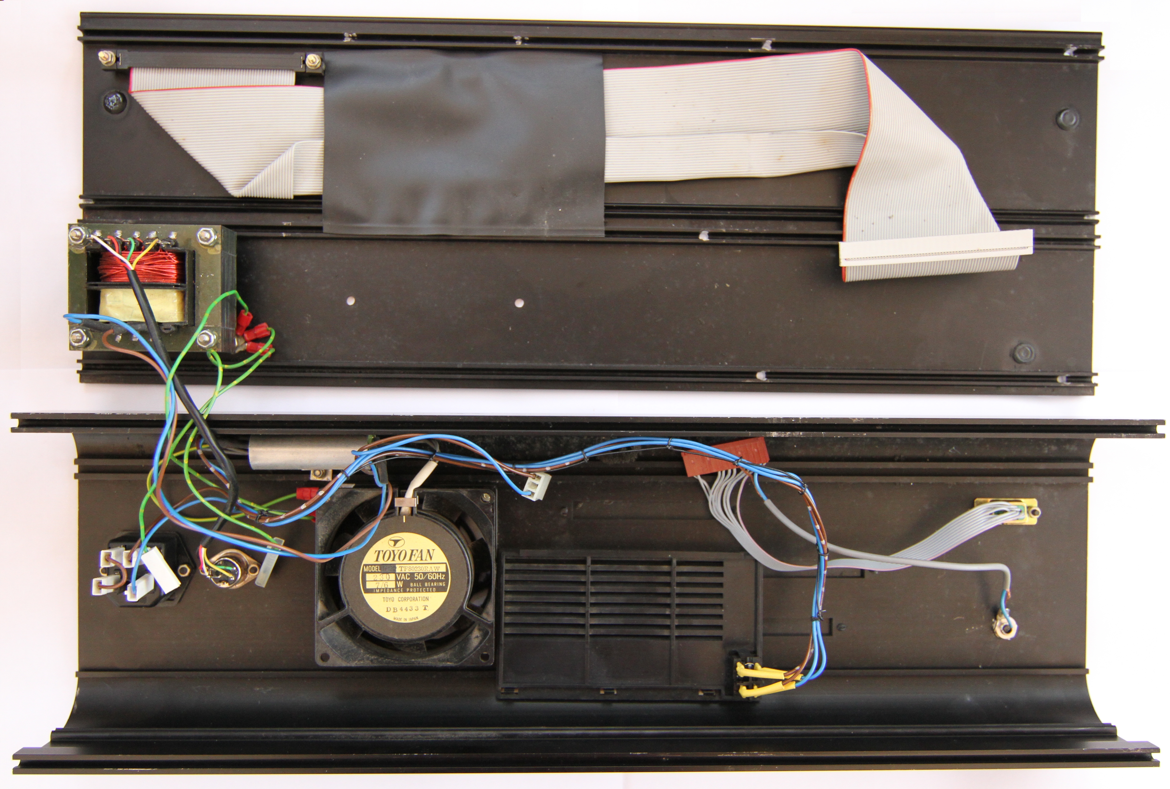
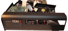
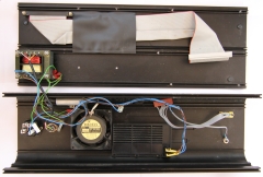
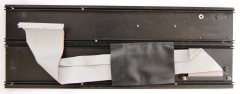
Stripped down to the (almost) bare minimum.
The only thing left, which should not usually
need to be disturbed, is the ribbon cable that
links the external connector to the SM1
Interface board in the card frame. The black
plastic sleeve provides additional insulation and
protection between the solder side of the PSU
PCB and the ribbon cable. |
 |
|
Reassembly |
| Like all good instruction manuals
say . . . . . . |
Reassembly is just the reverse of
the above steps

(Award yourself extra points if you have some screws
left over! ) |
|