|
Miscellaneous |
|
Martin Allcorn's
"Ex-Bricked" MTX
Martin has made extensive repairs to
one of his machines that had major problems, to such
an extent that it was formally referred to as "The
Brick". I think that the number and type of repairs
deserve a little space on this page. |
| Martin's tale of resurrecting this MTX
can be found here
The next photos give an idea of the major
components replaced in the process : |
 |
| This MTX started life as an MTX500, i.e., it had
32K of RAM. In common with a few of us, Martin had
previously tried to replace the on-board RAM without
success. More recently he has been successful -
see
here for details |
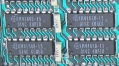 |
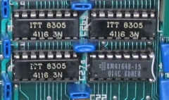
| A common problem with the MTX is failure of one
or more of the Video RAMs.
Quite a few people have
replaced a failed VRAM
with a like-for-like 4116, Martin has used a more
reliable 4164 instead -
see here for
details |
 |
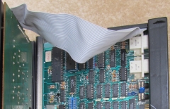
| Like many others, the ribbon cable connecting
the keyboard was also broken, Martin just replaced
it with a standard IDE cable. Other options are
also available -
see
here for details |
 |
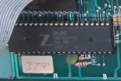
| A 10MHz CPU was installed when Martin was
over-clocking the CPU at 4.9MHz (as opposed to the
standard 4 MHz). The over-clocking has now been
removed, but the CPU remains. |
 |
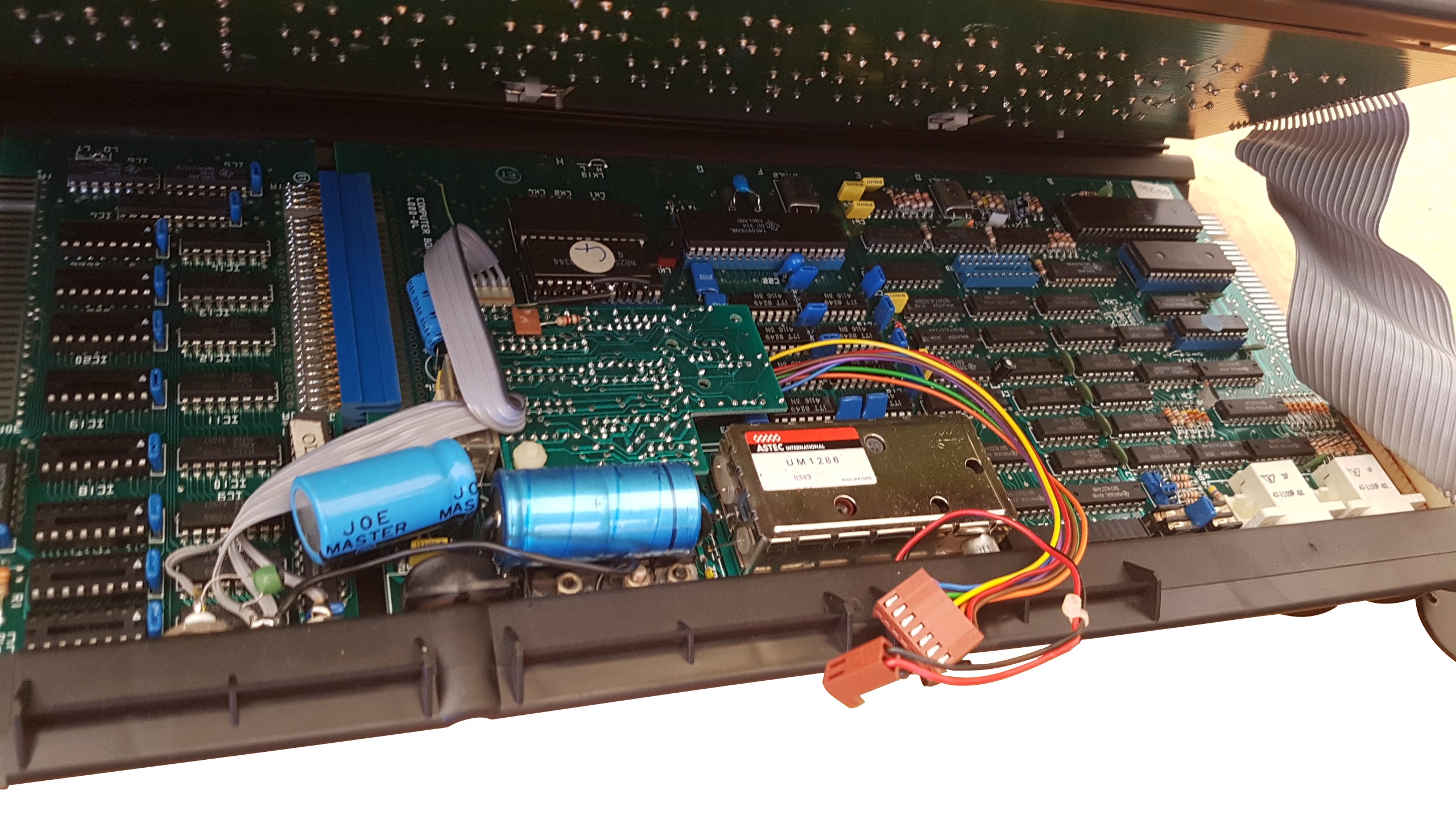
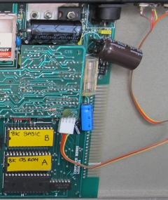
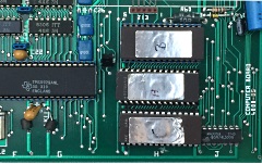
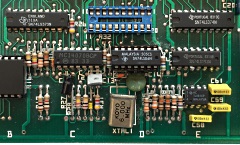
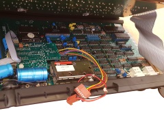
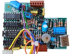
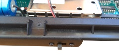
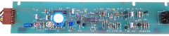
| The MTX uses a 4-way ribbon cable to connect the
audio and video outputs on the rear panel to the
video daughter board. This cable is also prone to
breakage at the rear panel connection, Martin has
also replaced this cable as shown. You can also
see the TIP2955 and smoothing capacitors
have been replaced to fix power problems, although
not visible, the 5V and 12V regulators were also
replaced.
Replacement of the capacitors has been described
by David Kimberlin-Wyer -
see
here for details
The photo also show new labels on the ROMs,
Martin replaced the original mask ROMs with EPROMs. |
 |
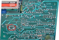
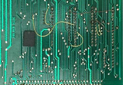
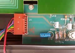
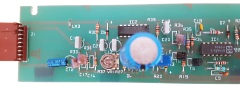
| Martin also fitted the jumper highlighted in the
photo.
This jumper position, and the open link position
beneath it, are shown on the
MTX video board
schematic as links "a" and "b". They are used to
select either mono or colour composite video output.
Martin had to swap the link position to enable
colour composite output, but all of my MTXs have
colour video output, suggesting that was the default
position. |
 |
|
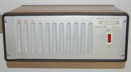
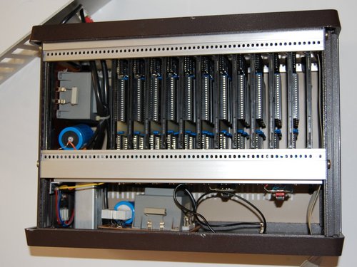
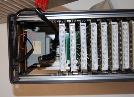
MTX Germany User
Club RAM Card |
Bespoke 512kB RAM card designed by the MTX Germany
User Group.
Photos courtesy of Eugen
Kaschubinsky.
Eugen has advised that "it was
*not* compatible to the MTX paging routine (#FA7A
still gave 0 or 1). |
 |
| It was used with the MTX Germany User Group's
‘multi-threading’ software running under CP/M. I
don’t know what it was called but it used ASCII
graphics boxes where you could ‘park’ running
programs…. " |
 |
|
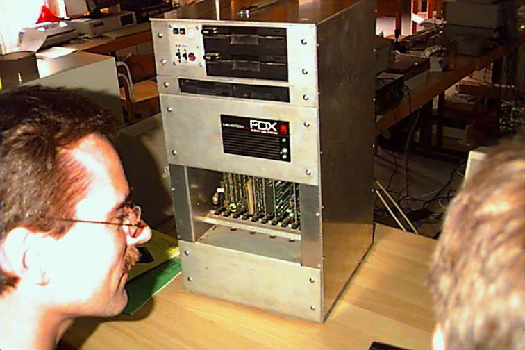
A DIY DART Enabler? |
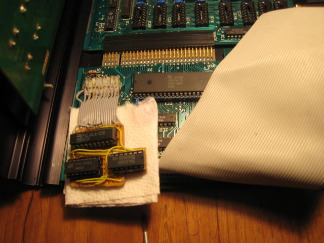
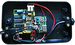
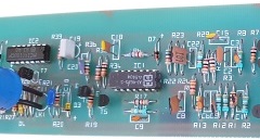
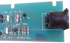
| This PCB in this photo
is the FDX Interface / RS232 card installed in the
MTX/FDX auctioned on ebay.uk in July 2014. Martin,
the seller, recalls that he made the small PCB to
enable one or more of the RS232 ports, although,
after twenty odd years, the details are a little
hazy.
Not all FDX interface boards had the RS232
components installed and the on-board PAL was not
configured to enable the DART. |
 |
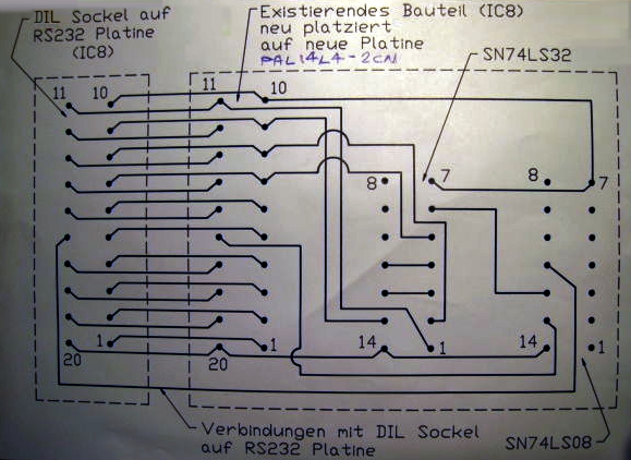
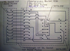
| The sketch is Martin's circuit diagram from the
time, he cannot recall the exact function of the
PCB, but I think that it must have been used to
perform the DART enable function that would have
been done by the PAL on cards supplied with the
RS232 components installed and the ports enabled.
Photos courtesy of Martin G. |
 |
|
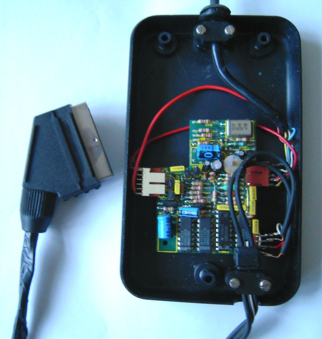
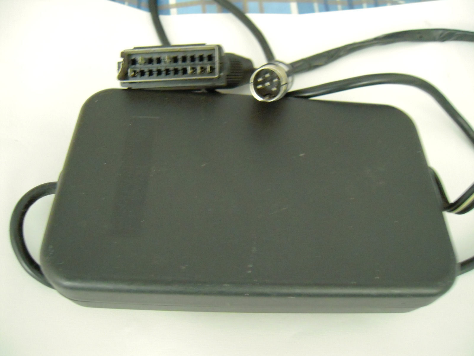
A Wasted Video Board ? |
| A novel use for an MTX video board, it has been
used to convert the 6-pin Audio/Visio output from a
Texas Instruments TI99/4A to SCART. These
photos were taken from the listing page when the
item was sold on ebay UK in May 2015 |
 |
| The MTX Video board has been mounted in the box
for the original TI modulator. |
 |
|
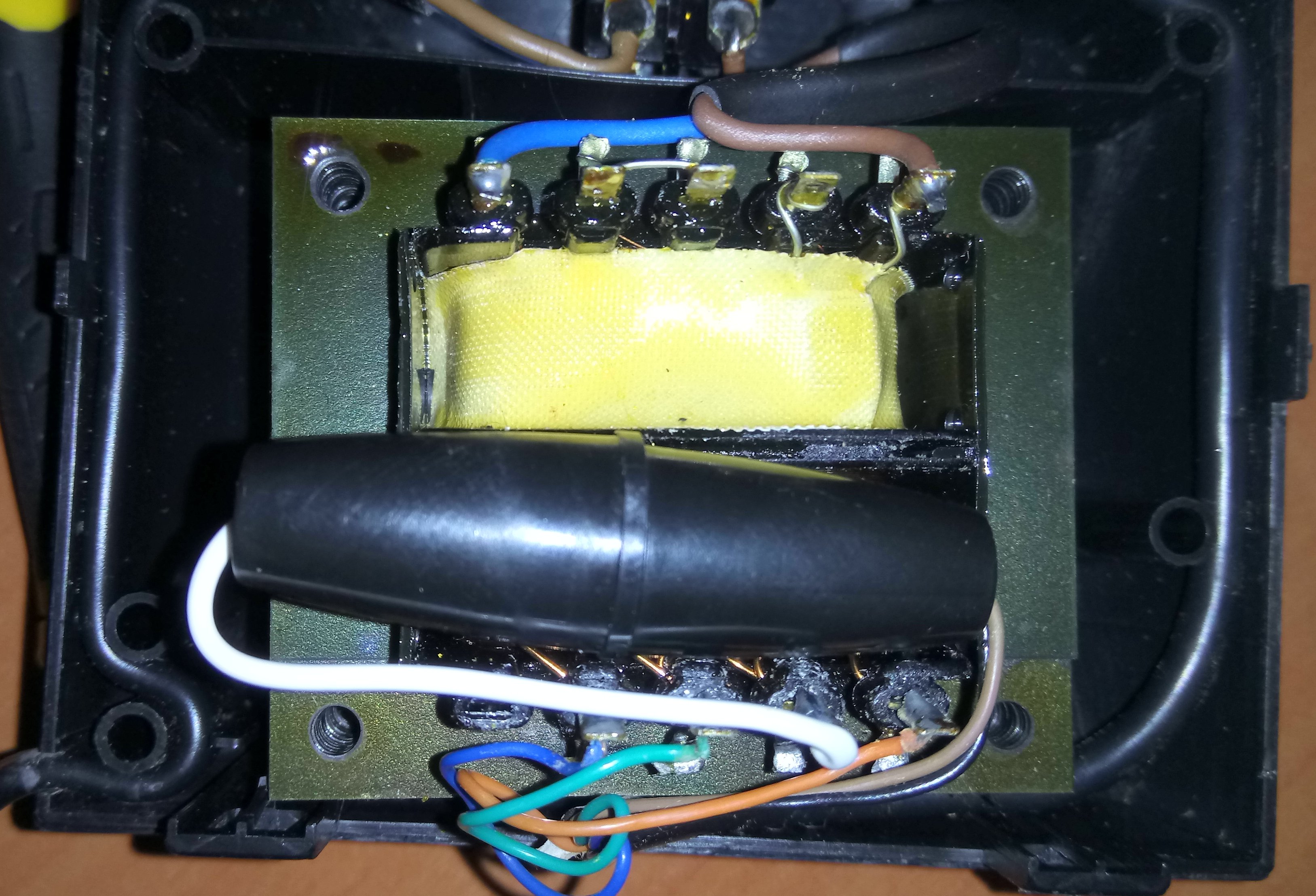
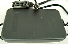
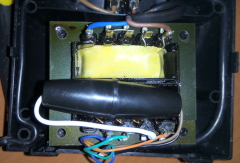
Power Crazy ? |
Internals of an MTX PSU from a non-working MTX.
The PSU had a two pin Euro mains connector and what
looks like a user added fuse installed internally.
As of July 2020, this PSU is under
investigation on
Memorum
Photo courtesy of Steve G. |
 |
| |
|
|
MTX Customisation |
Manfred Flume generously donated a
couple of MTXs and an FDX to me in 2016. Manfred was
an active member of the
MTX User's Club,
Germany back in the day and made quite a few
modifications to his MTXs, as well as writing
various pieces of software for Tape and Disk.
One of the MTXs that he donated was in an MTX500
case, but the computer board was populated with 64k
of original RAMs, i.e., it was an MTX512 board.
Manfred recalls that he had an MTX running at
8MHz using a customised clock circuit :
"It
should have a PLL generated clock which powers up
with approximately 4Mhz and goes slowly up to 8Mhz
as some parts did not work when I used a 8 Mhz
crystal. But when I started with 4 Mhz and increased
the clock in some seconds it worked. So I designed
this clock circuit." |
| |
|
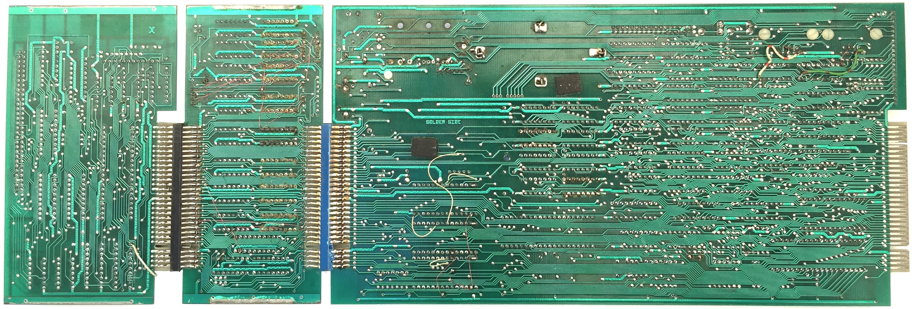
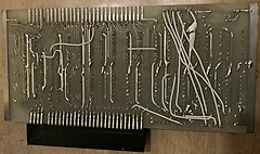
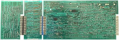
Solder side of the boards inside Manfred's
"MTX500"
The full size image shows that a
number of modifications have been made with jumper
wires between various points. |
 |
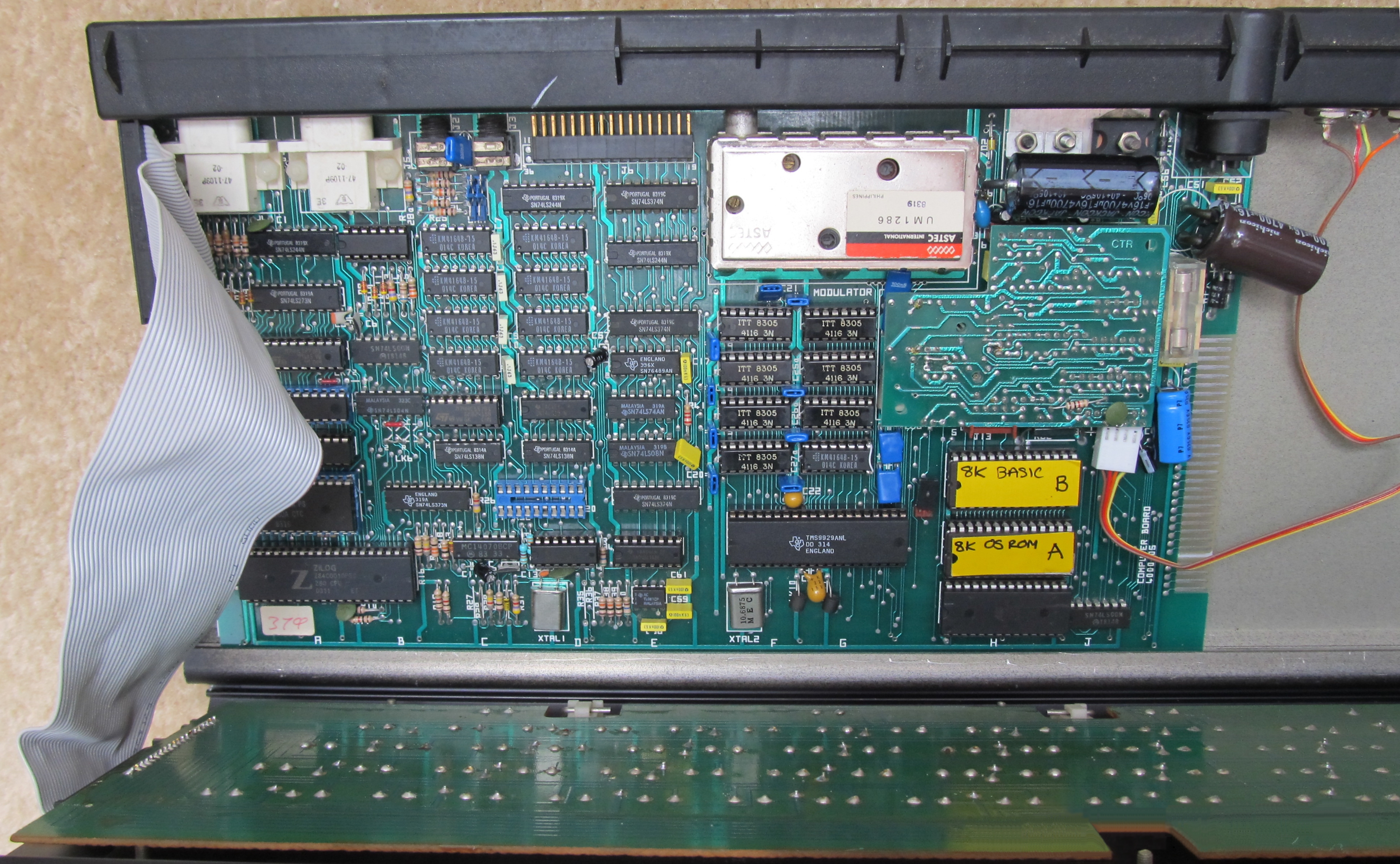
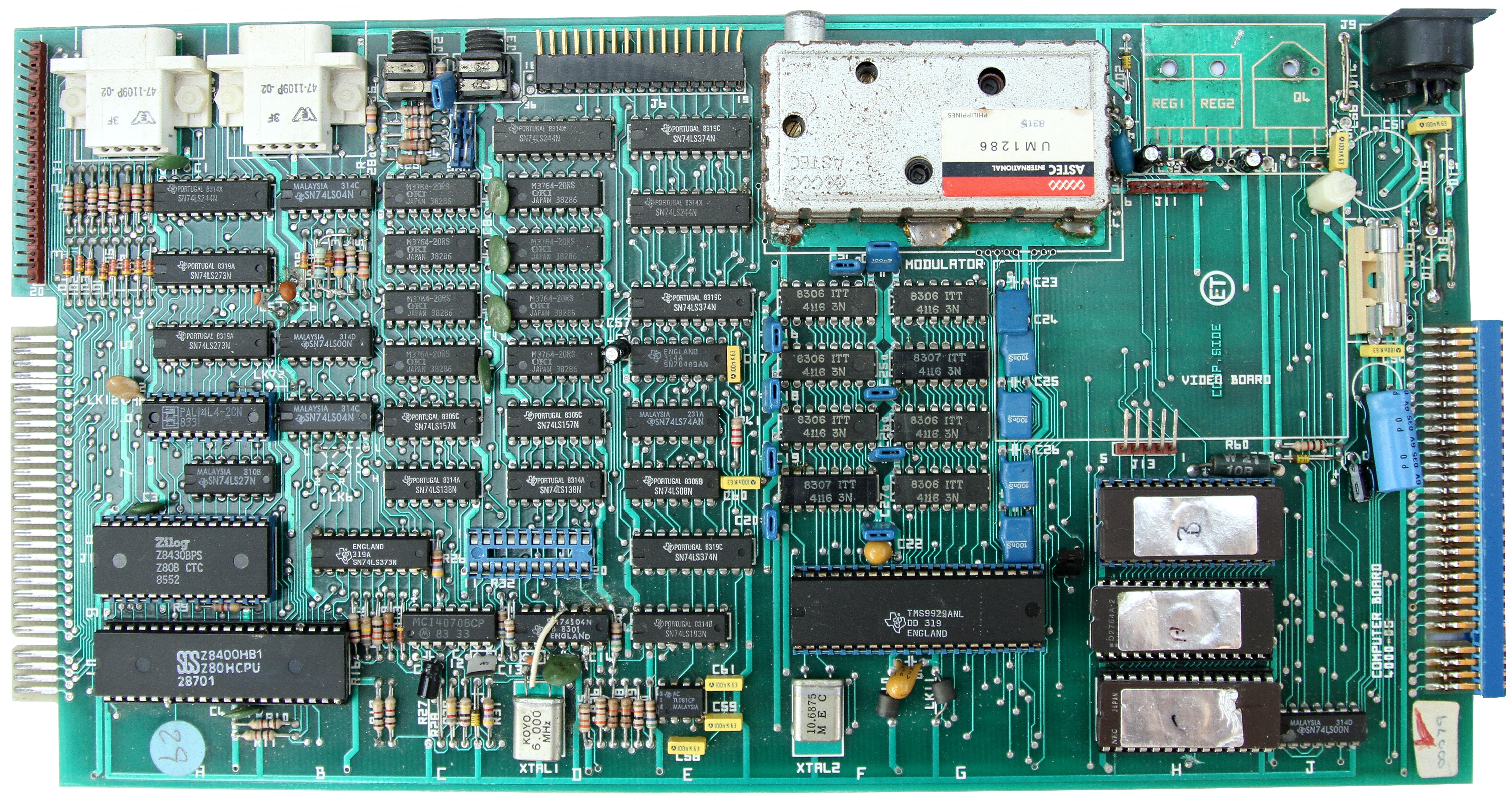
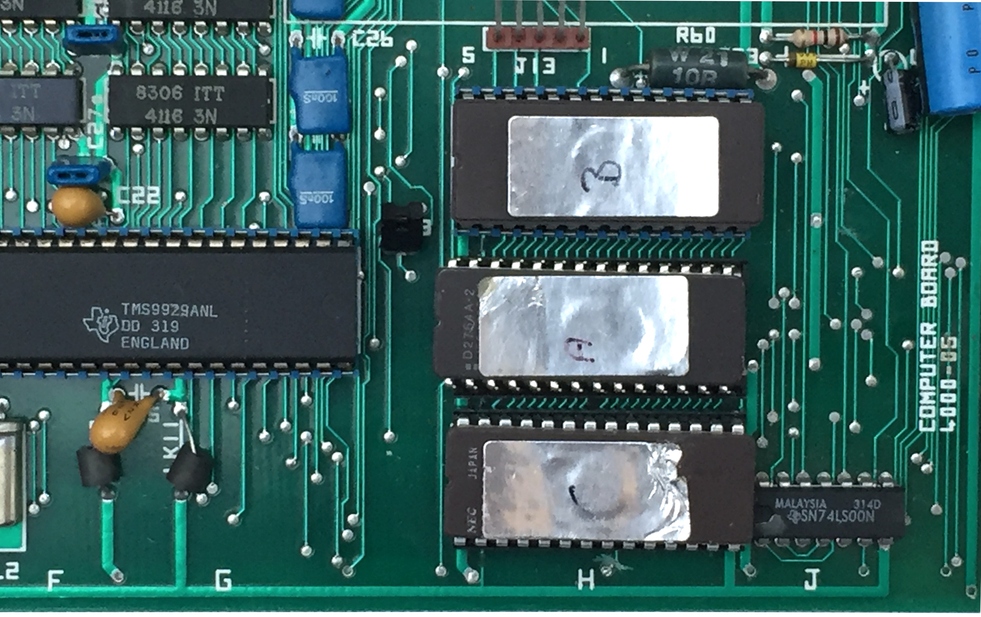
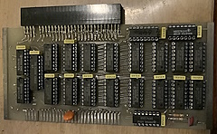
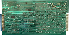
The 4000-05 computer board inside Manfred's
"MTX500"
I think that the "MTX500" may have
had the customised clock circuit installed at some
point, although it has been removed, there are some
artifacts on the computer board that suggests that
this was the case. |
 |
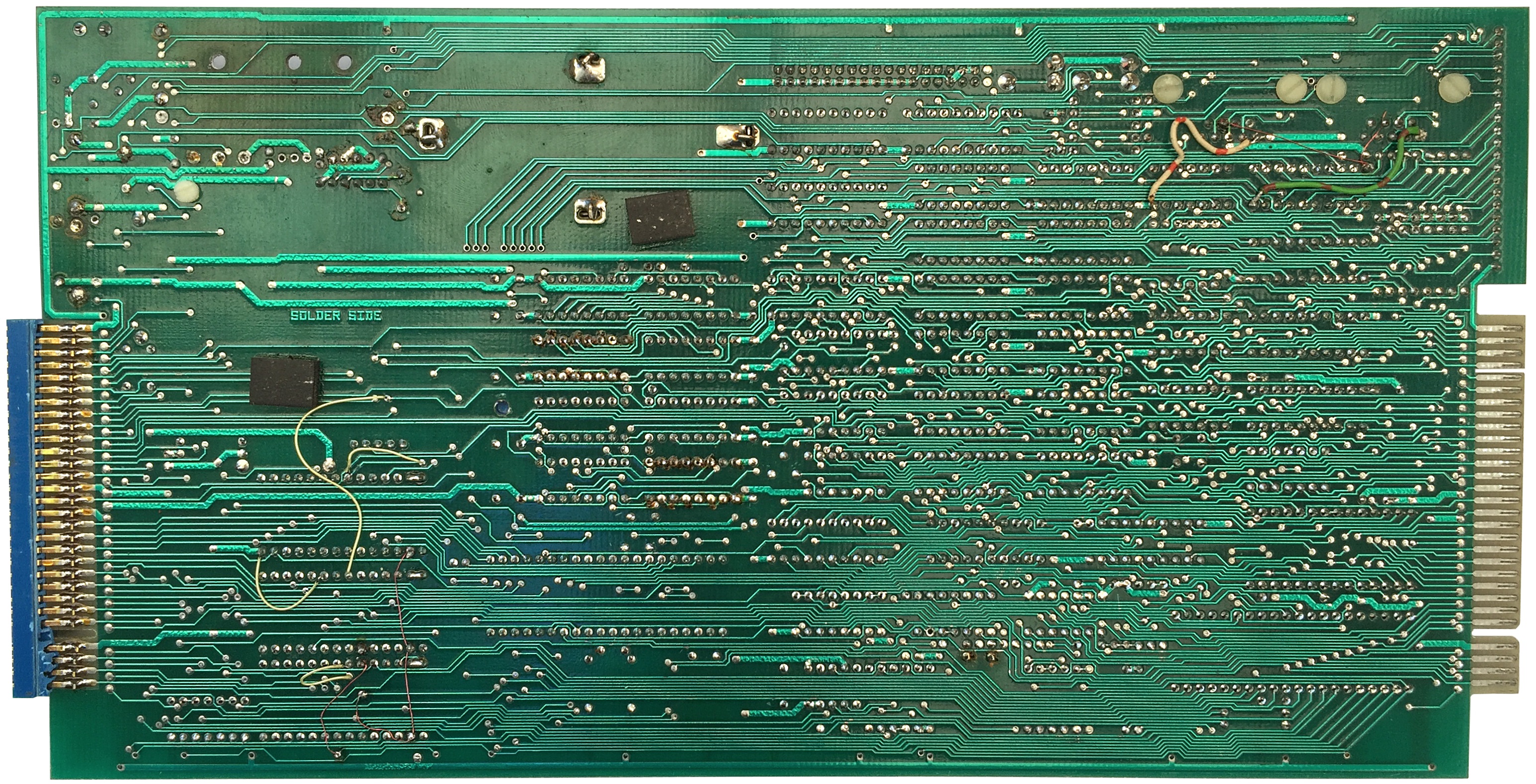
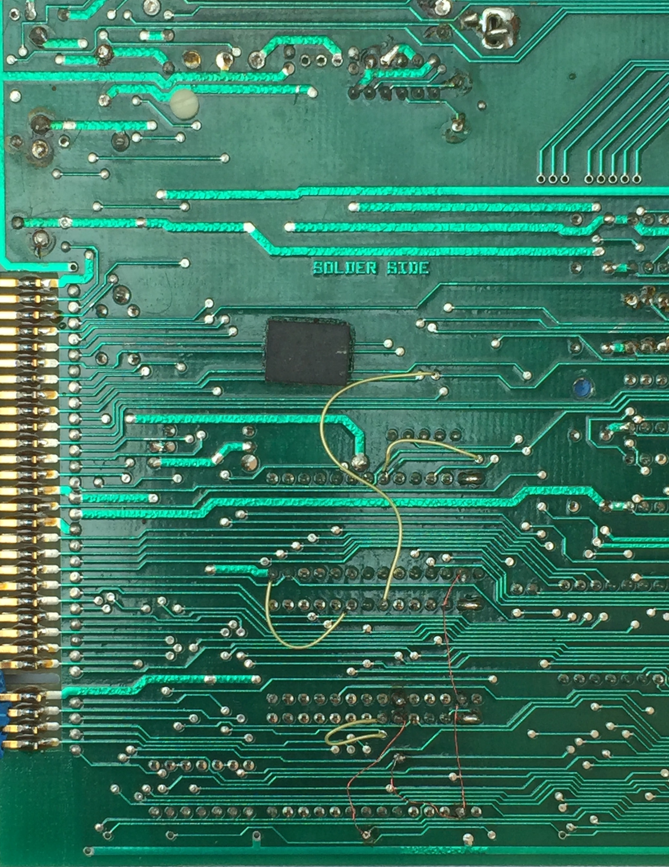
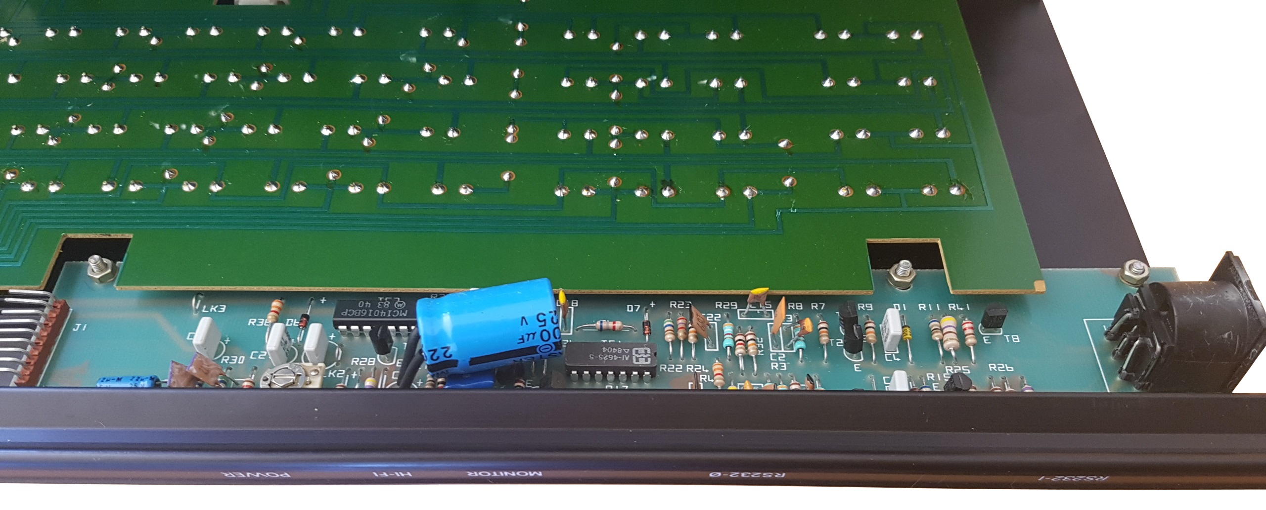
| Solder side of the computer board. |
 |
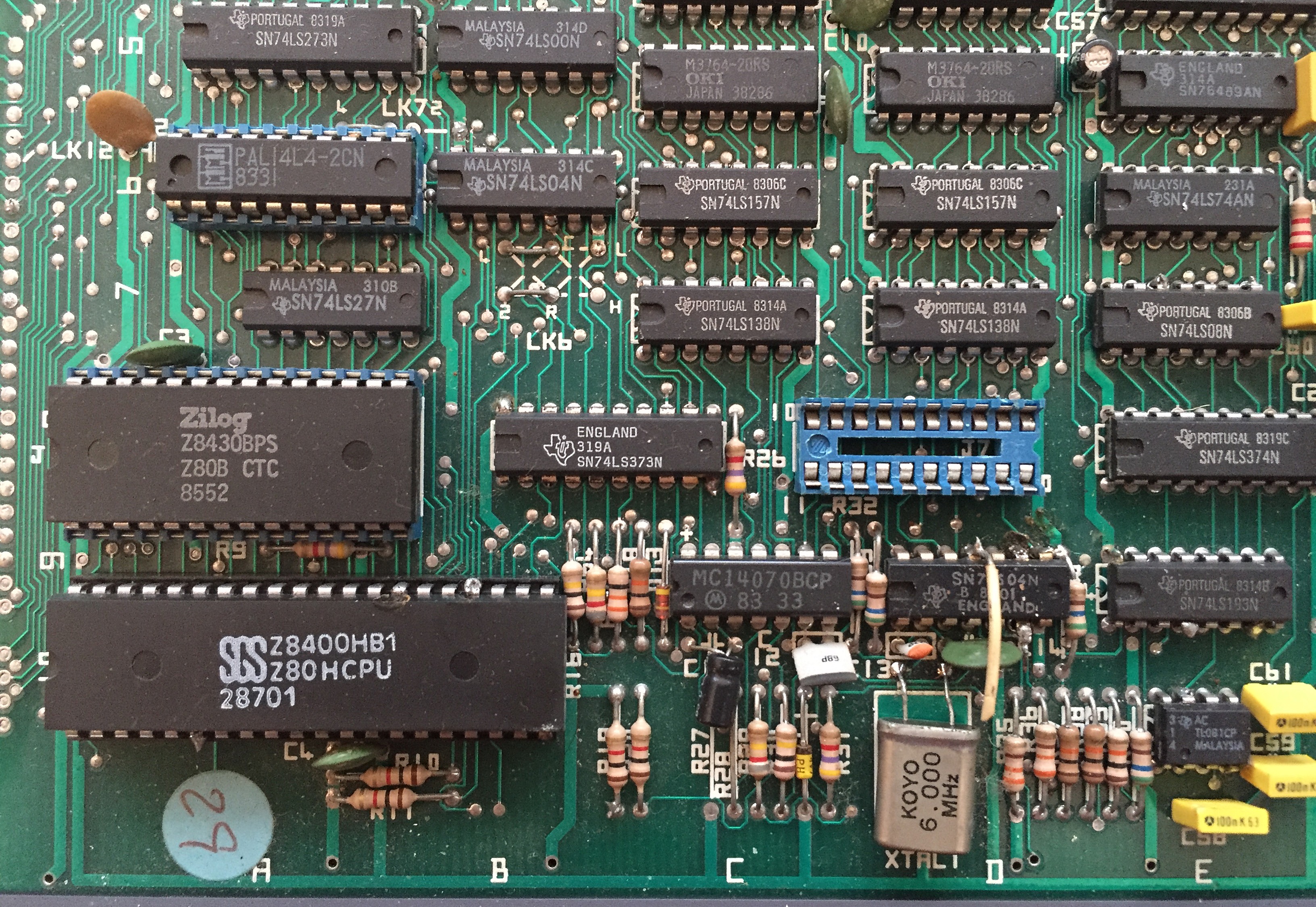
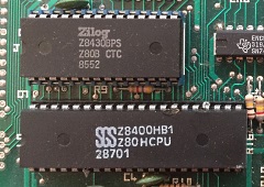
The original Z80A CTC (MHz) has been replaced
with a Z80B CTC (6MHz) and the original Z80A CPU
(4MHz) has been replaced with a Z80H CPU (8MHz).
Wires appear to have been soldered to CPU pins 6
(CLK), 24 (/WAIT) and possibly 27 (/M1).
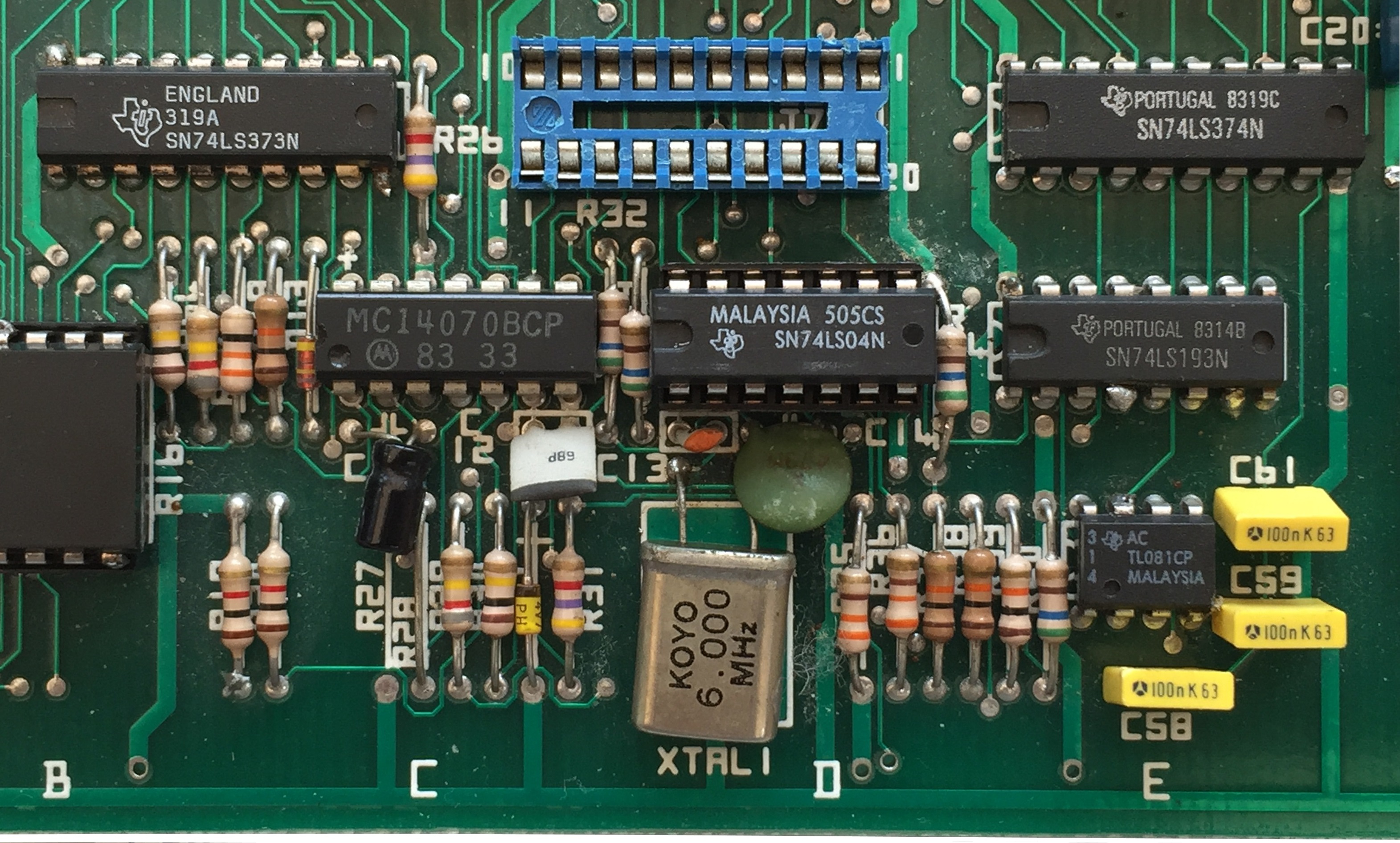
As
shown in the photo below, the original 4MHz
oscillator has been replaced by a 6MHz one. |
 |
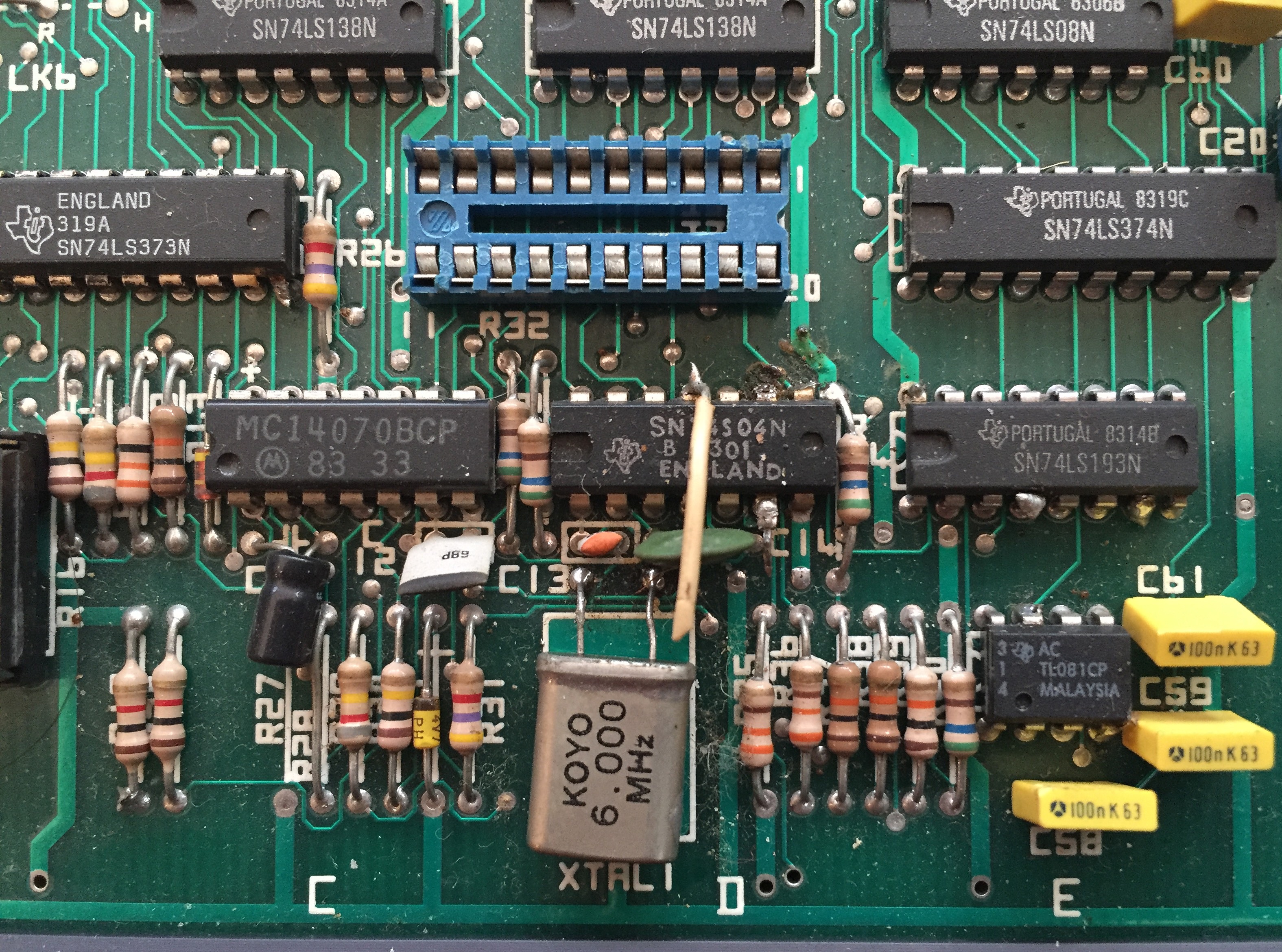
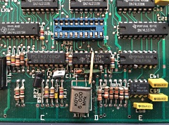
An "orphan" wire is soldered to pin 11 of the
LS04 quad inverter in board position D9. The
circuit diagram for the MTX clock shows this was
the input to the inverters for the final stages of
the clock signal to the CPU, CTC and bus.
The
original input to this pin was from pin 6
(disconnected), driven by the oscillator circuit.
Manfred's PLL circuit must have been placed between
these pins, with this circuit removed, this MTX does
not have a working clock! |
 |
With the CPU running significantly faster than
design, timing dependent functions in the ROM, such
as the clock, cursor flash, keyboard repeat rate,
etc. would run too fast.
Perhaps having
modified the ROMs to cope with the faster speeds,
Manfred appears to have replaced the original ROMs. |
 |
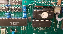
The original mask ROMs on the 4000-05 computer
board were 24 pin TMS4764 (8K) devices.
The
replacement EPROMs installed by Manfred are 28 pin
devices (Nec D2764), the solder side of the PCB
shows that how the ROM sockets have been modified to
suit. |
 |
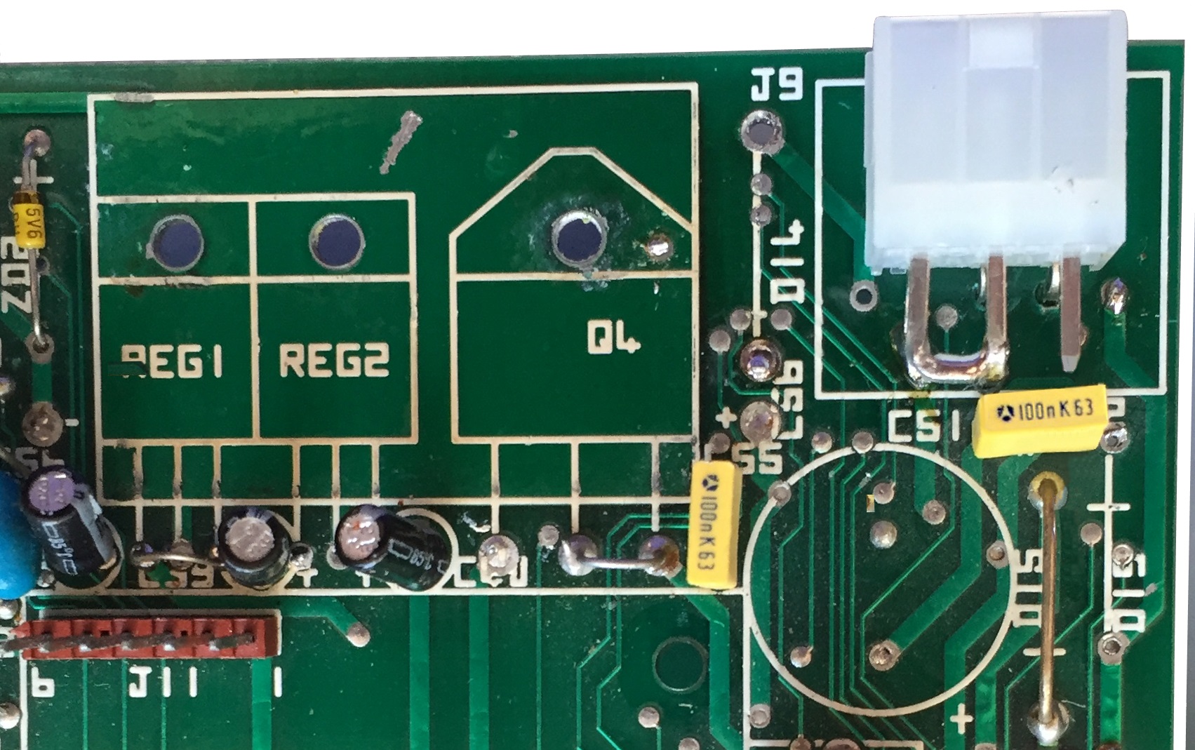
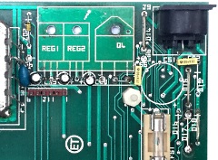
This MTX has had the majority of its power
regulation components removed. Manfred recalls that
"the MTX 500 had, as other MTX boards, a thermal
problem with the regulator circuit. So I replaced
this with an other Power supply as I did not manage
it to get the regulator cooler. "
(Memotech
did the same when they used a MTX computer board and
a "Skynet"
PSU to build the
Reflex Controller in my Video Wall system.) |
 |
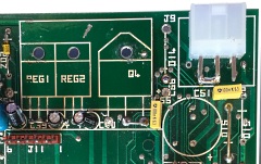
I modified the computer board to accept the plug
from a Cisco ADP-30RB router PSU. These PSUs provide
+12v, -12v and -5VDC and are readily available on
eBay, making a good DC only PSU for the MTX.
Read about how I converted the MTX
on this page. |
 |
With a working PSU, the next job was to replace
the butchered 74LS04 used to generate the MTX clock.
Here you can see a replacement 74LS04 fitted in
a new socket that replaced the old chip. |
 |
With the 74LS04 replaced, the new DC power
supply connected, and the MHz oscillator still
fitted, somewhat to my surprise, the system booted
first time.
The system appears stable under
MTX BASIC, although clock dependent functions such
as the keyboard repeat rate, cursor flash and the
clock all run fast. A 30 "second" count on the
system clock takes 20 seconds, consistent with the
CPU running at 6/4 times normal speed. |
 |
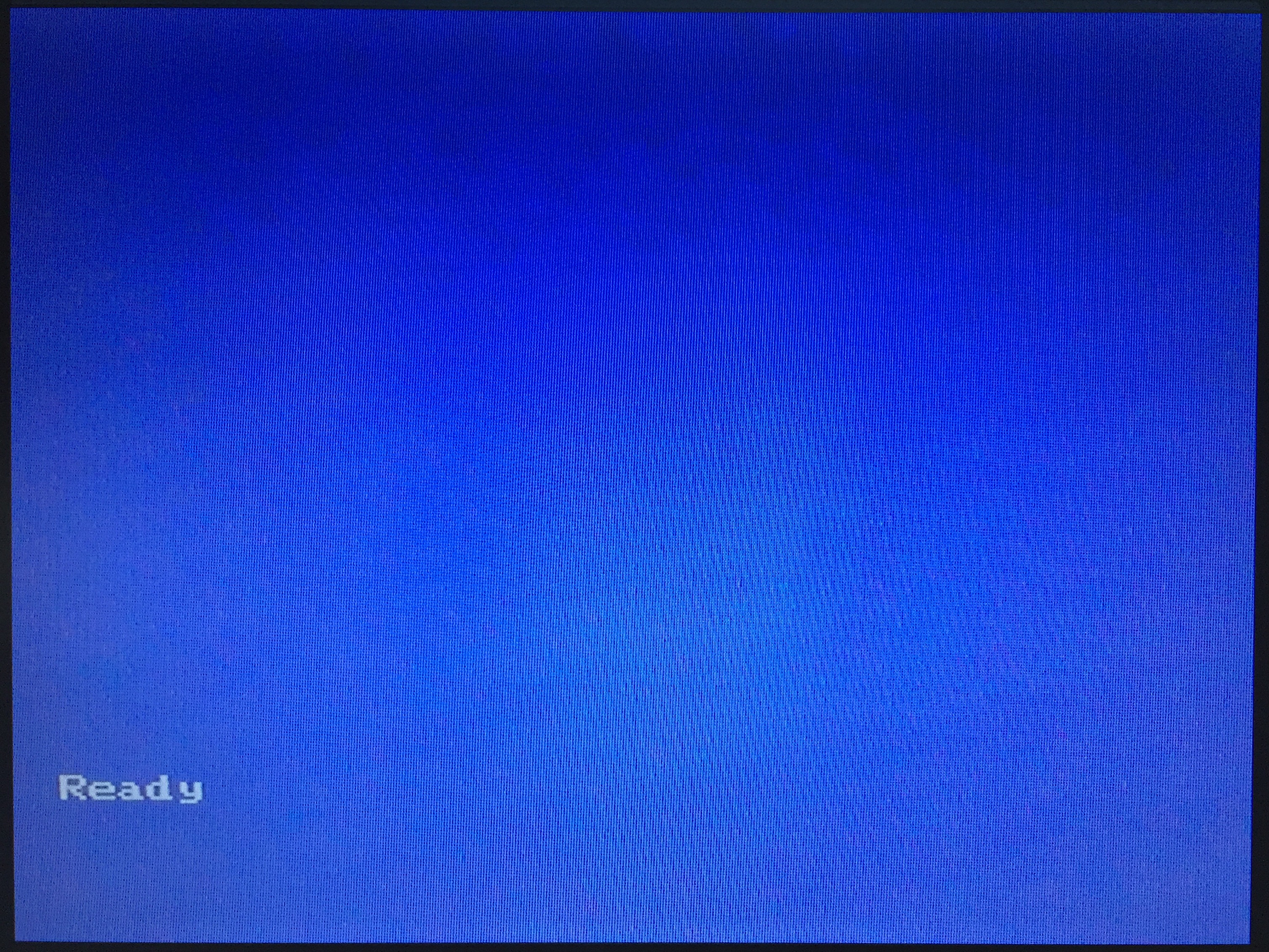
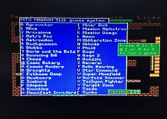
The system boots
MAGROM and
displays the Game menu correctly so ROM access seems
to work OK at the higher speed.
Unfortunately, none of the games can be run and the
system crashes when any are invoked. I guess that
the RAS/CAS signals and/or the RAM are just too slow
for 6MHz so it looks like I will have to replace the
oscillator with a 4MHz one as per design. |
 |
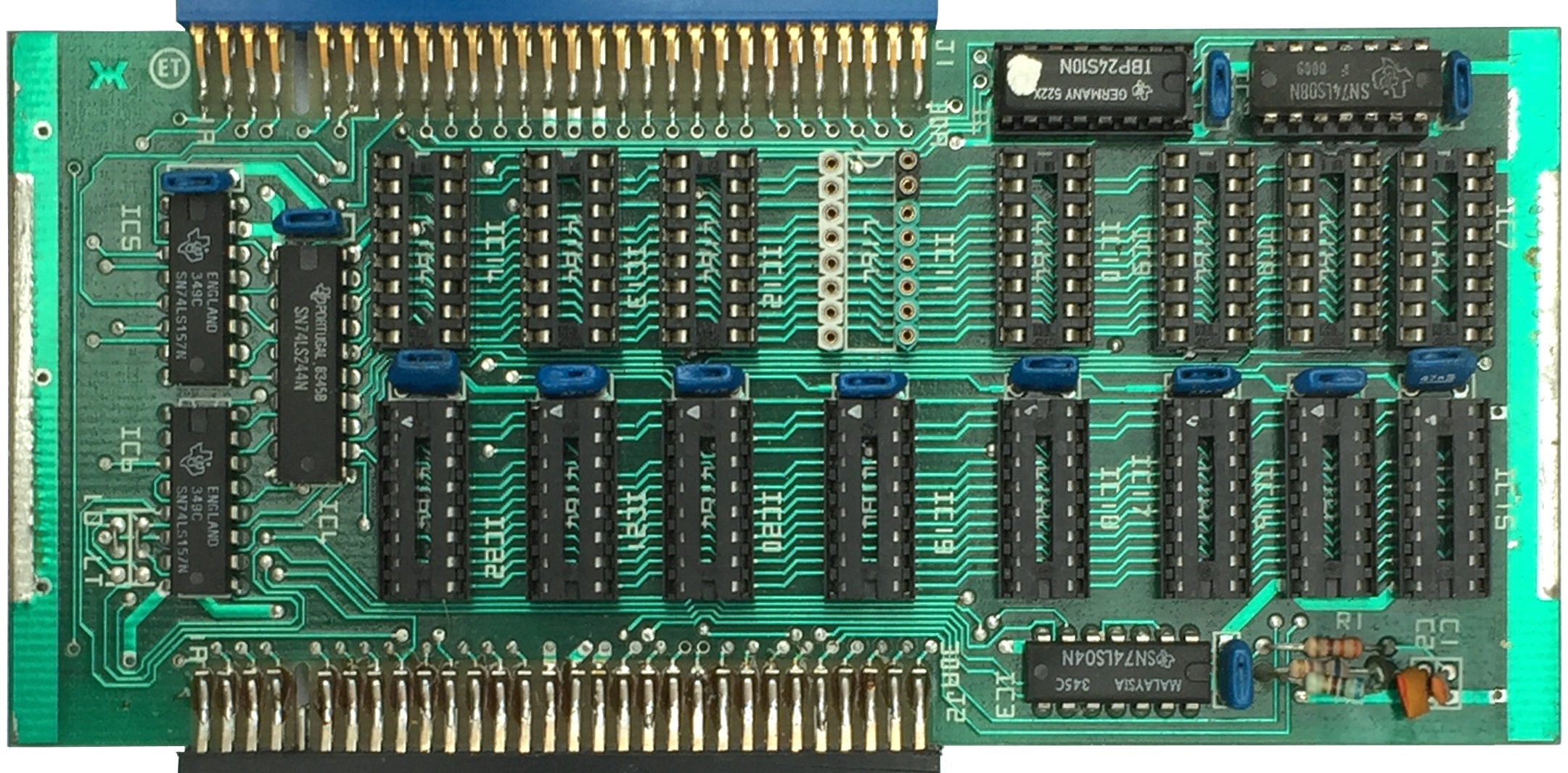
There is a MTX Memory Expansion board fitted,
but no RAM installed on it.
The original
Memotech PAL has been replaced with a TBP24S10 PROM,
one socket has been replaced, but there is no
obvious signs of any major modification. |
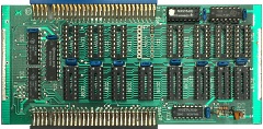 |
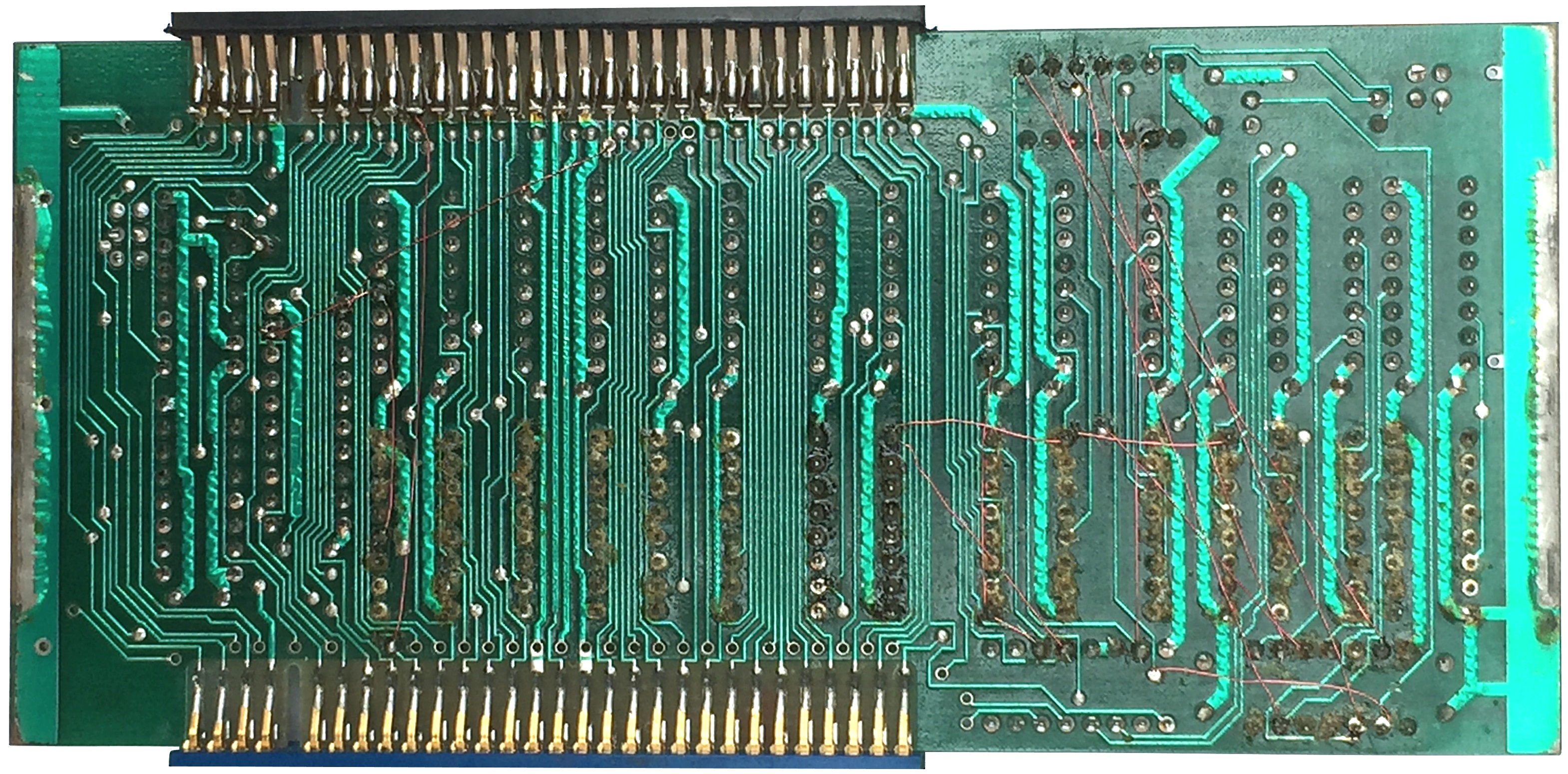
However, the solder side of the Memory Expansion
board has quite a few patch wires fitted.
I
will need to study the patch wires to try and work
out the modifications that were made to this board. |
 |
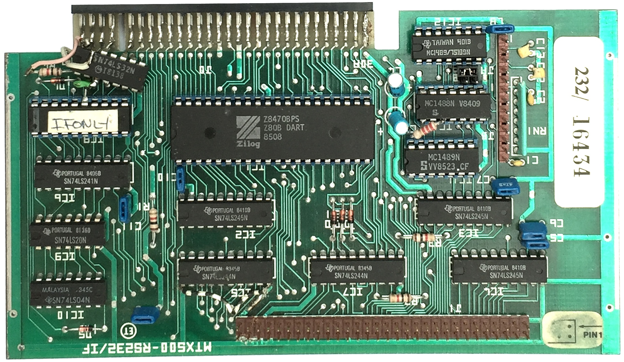
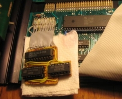
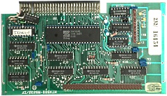
The FDX Interface board, with the original
Memotech PAL labeled I(nter)F(ace)ONLY. The DART and
other RS232 components have been retro-fitted.
A 74LS32 (Quad OR) has been soldered to the
board and some patch wires connected - probably to
enable the DART without modifying the PAL (PAL pin
15 = DARTEN). |
 |
Solder side of the FDX Interface Board
The
grey wire is connected to PAL pin 11 (A432)
The DART was enabled in a Memotech PAL by :
DARTEN =
A7 *
A6 *
A5 *
A432 *
IORQL * M1
The custom wiring should have replicated
this logic with OR gates - how good is your Boolean
algebra? - Prove :-) |
 |
| Inspection of the board shows that IORQL and M1
have not been used in the logic. Tony has pointed
out that the DART has its own
IORQ and
M1 pins, so does
not need them to be included in the custom enabling
logic. |
 |
| |
|
|
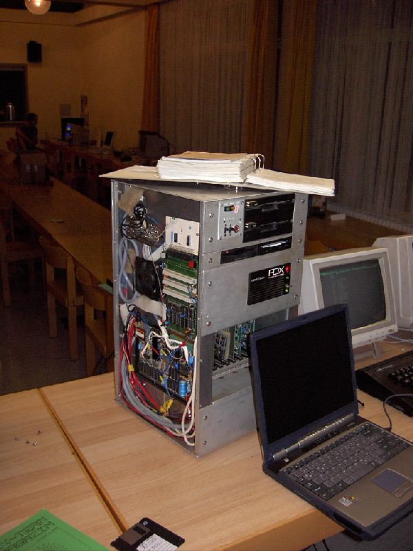
FDX Customisation |
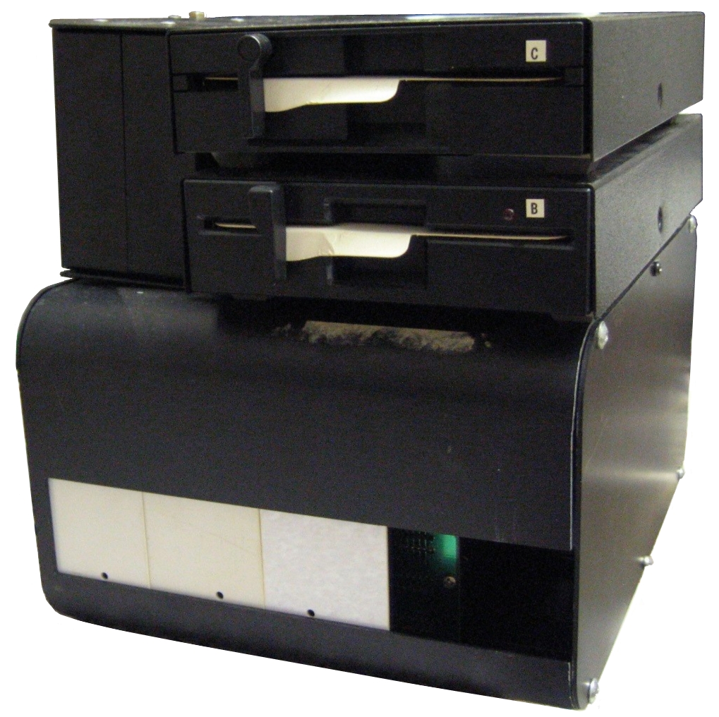
Wolfgang Joerger generously
donated an
MTX500 with an 32K RAM board and the FDX
interface board, along with what appeared to be a
Single Drive FDX, that had an after market upgrade
to add a second Epson SD521 floppy drive.
The
most interesting thing about the FDX though, is the
1MB self build Silicon Disk that Wolfgng had added
to the system. Not having a Memotech Silicon Disk
board in my collection, I had thought about building
one myself - thanks to Wolfgang - now I don't need
to! |
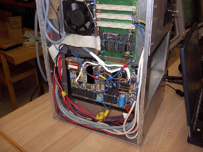
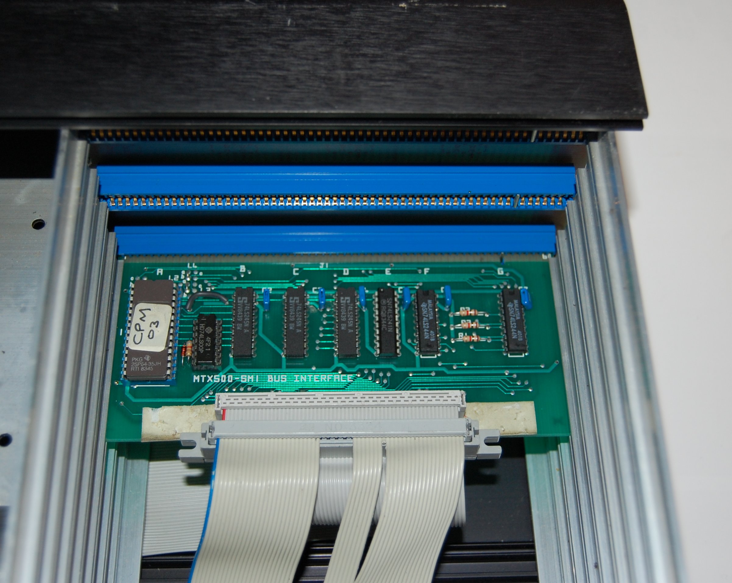
| Although the FDX card cage was designed to allow
additional cards to be added, none of the spare
slots had edge connectors preinstalled. Here you can
see that Wolgang has fitted an additional edge
connector in the second slot and installed a custom
interface board to breakout the FDX backplane to a
DIN 41612 socket. |
 |
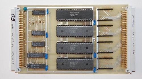
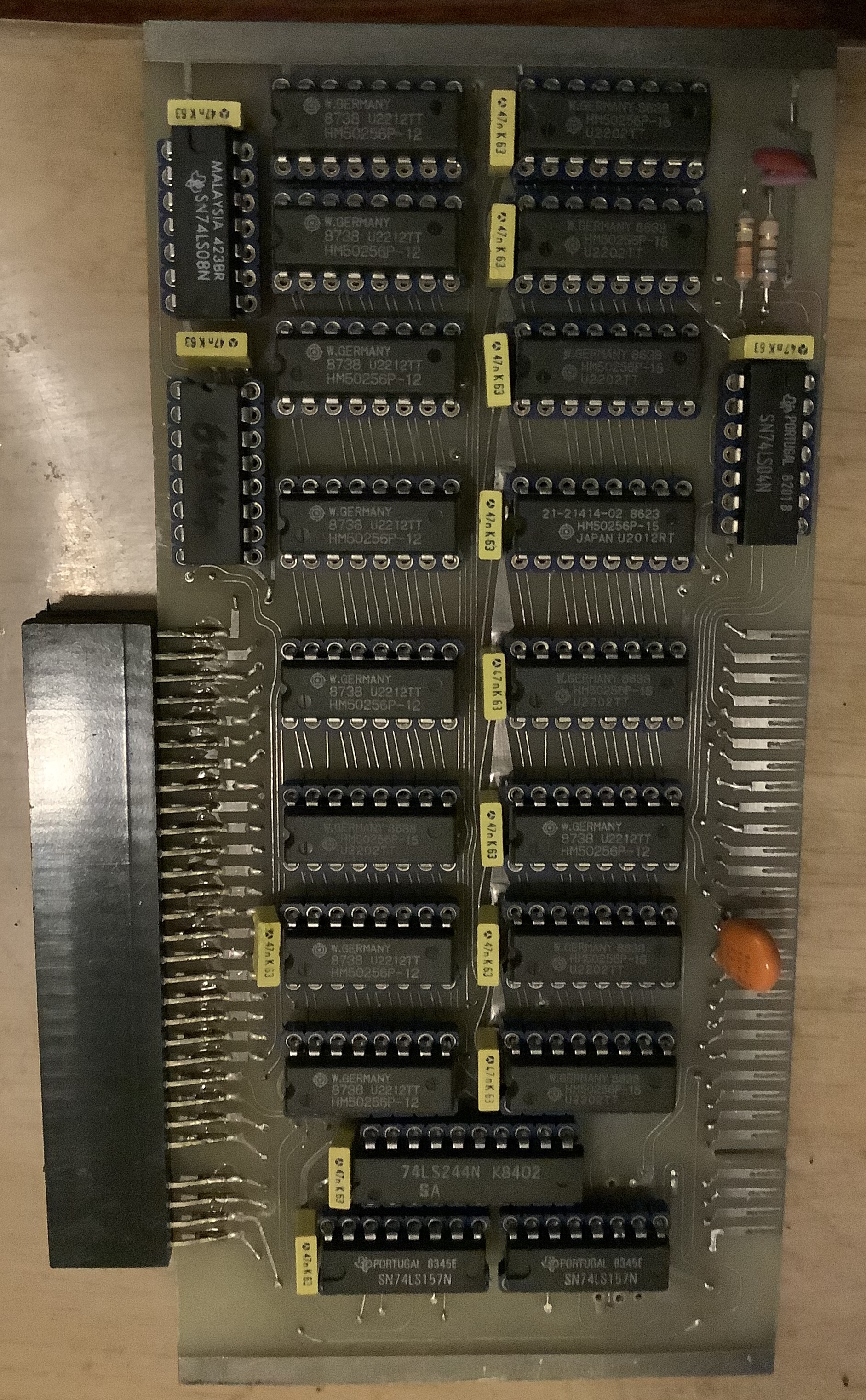
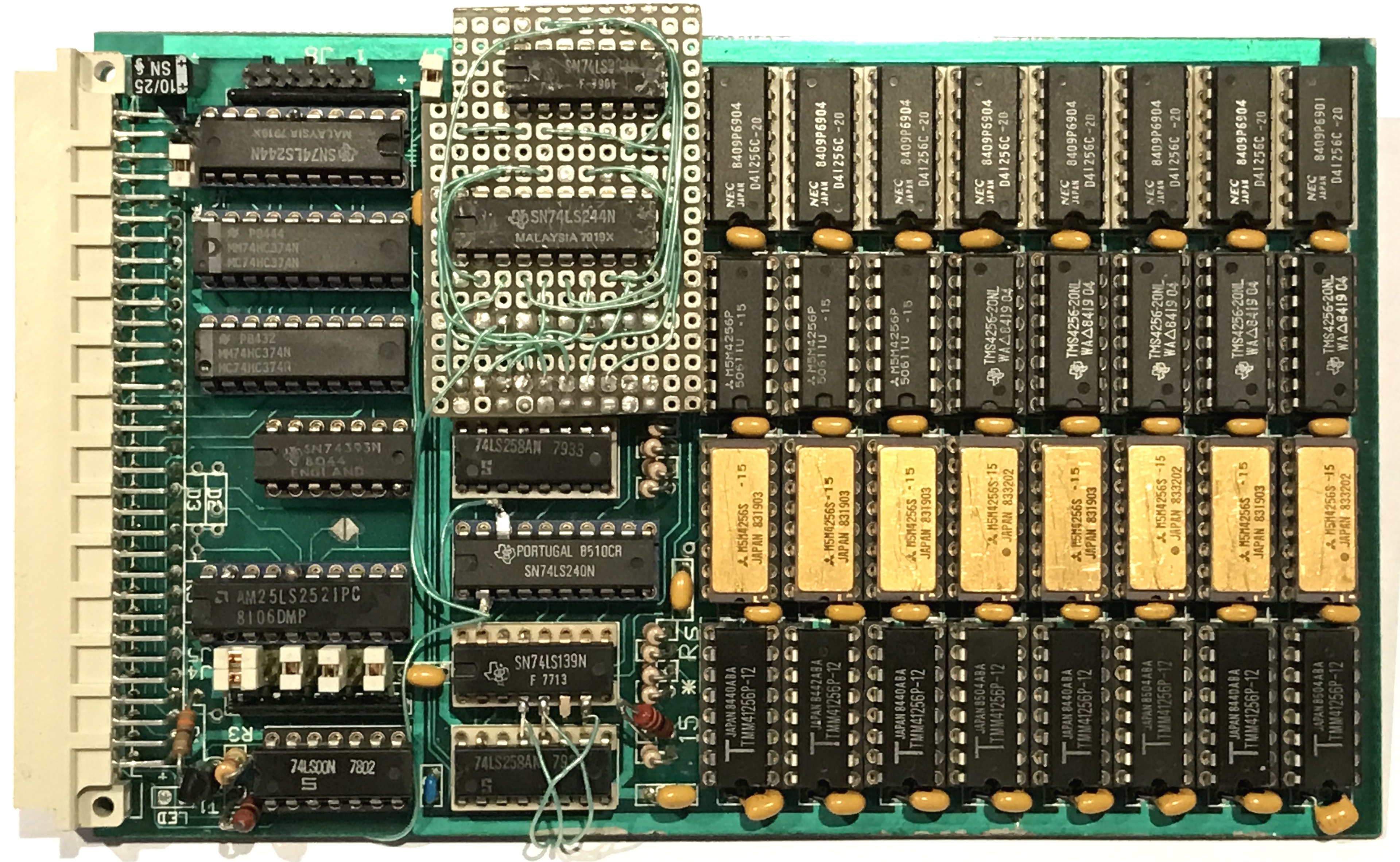
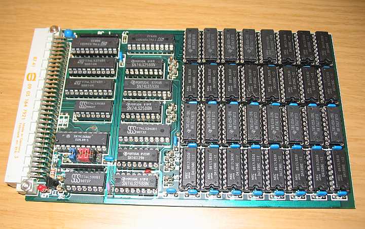
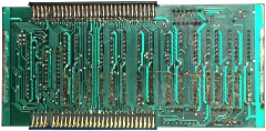
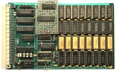
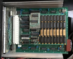
| Component side of the Eurocard board, showing
the 24 x 256 kbit RAMs, support logic, and what
appears to be a customised daughter board - perhaps
to enable a generic RAM board to be used to create
an FDX Silicon Disk? |
 |
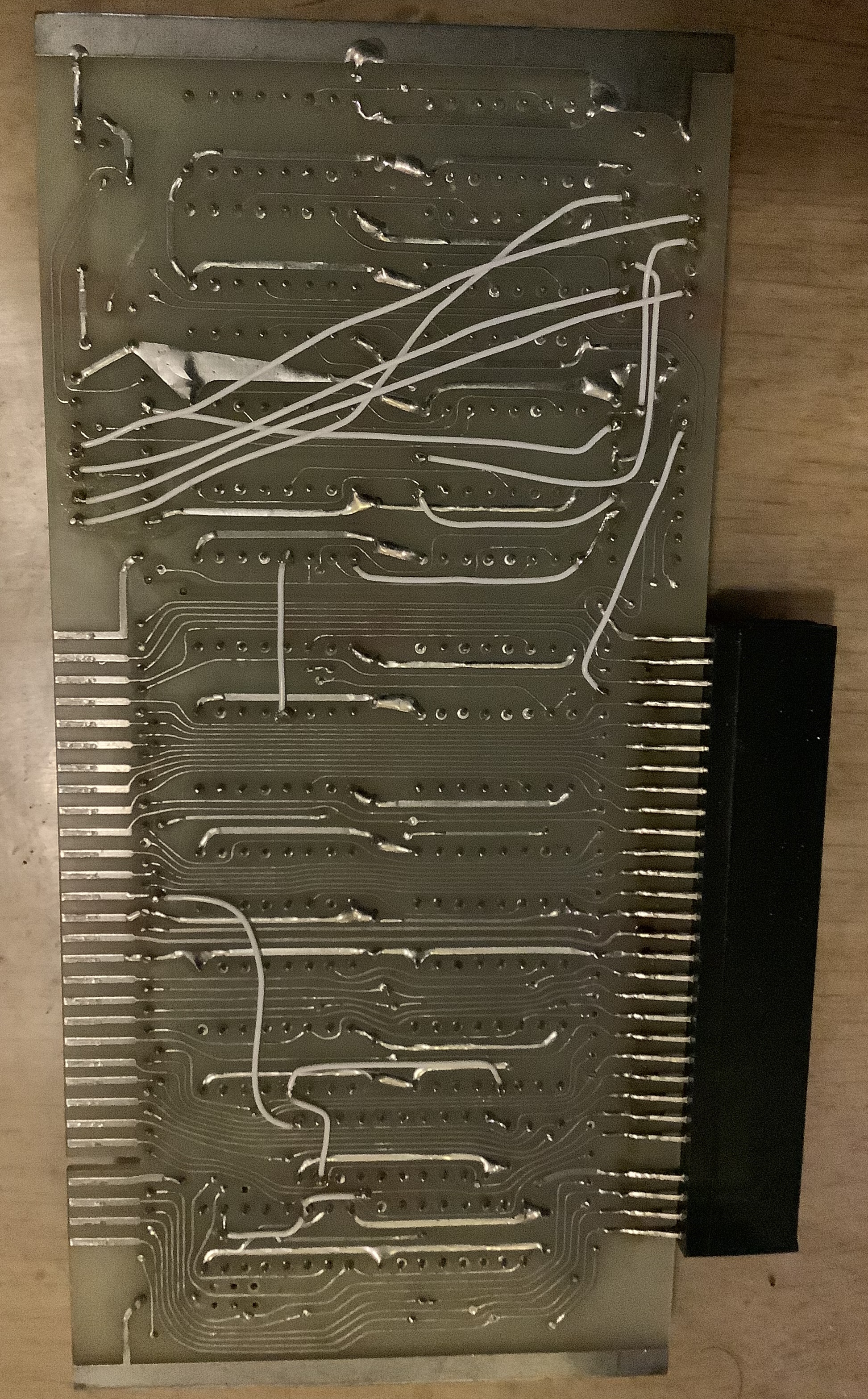
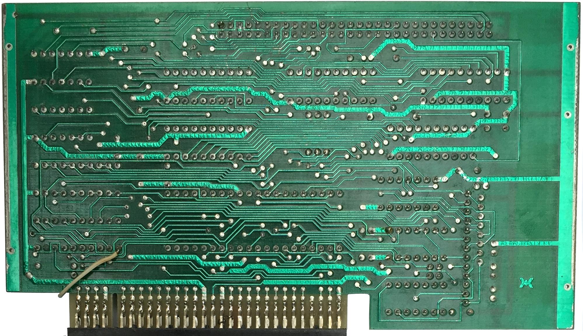
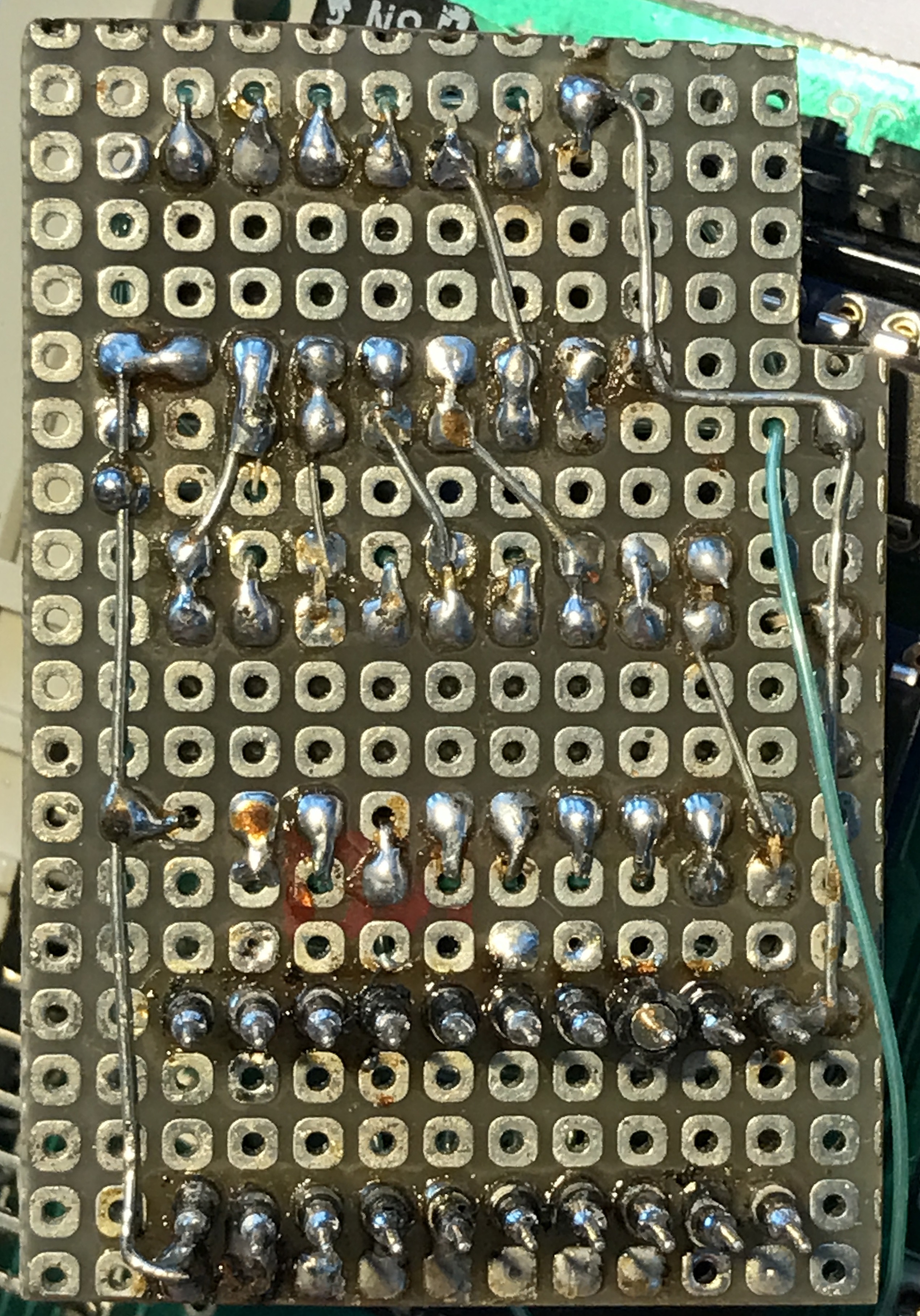
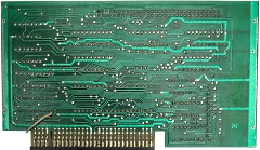
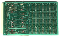
Solder side of the Eurocard board. The PCB has
some identifying marks, including Kayser,
RAM-Floppy and
V1.5.
|
 |
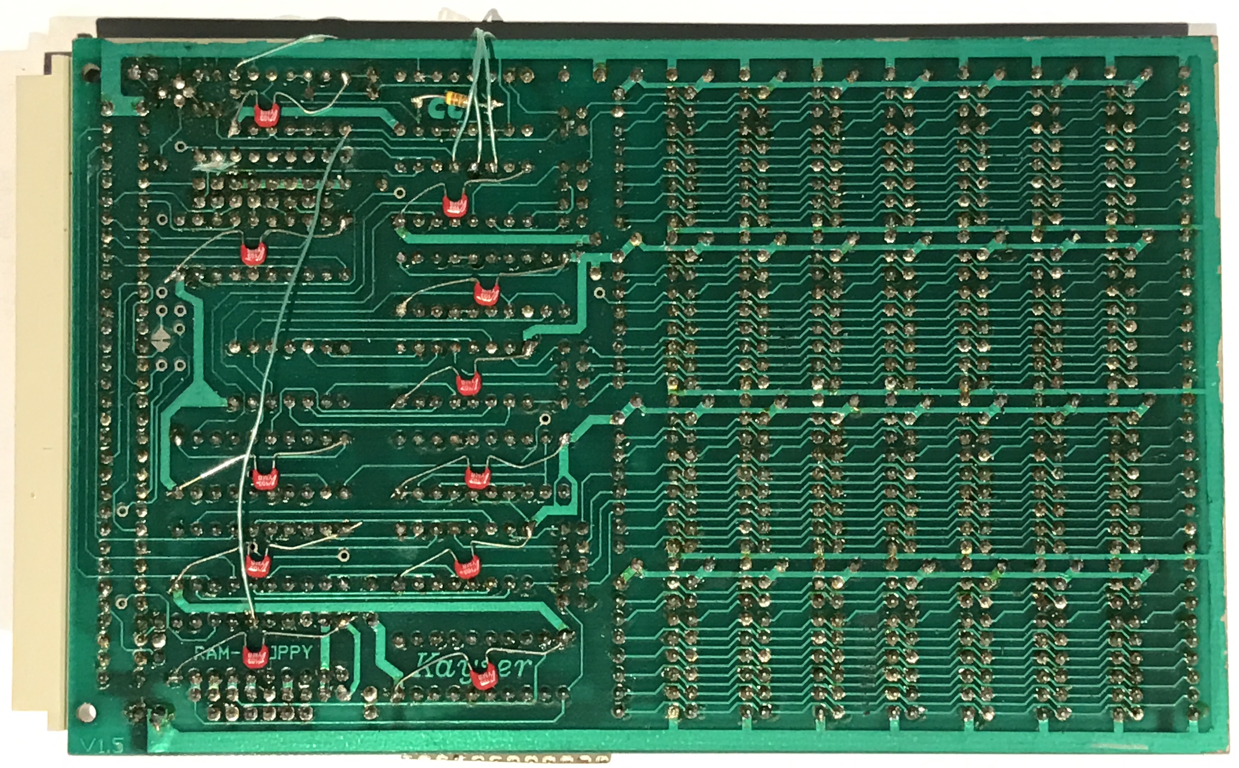
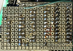
Solder side of the daughter board
Wolfgang
thinks that the daughter board and patch wiring were
configured to allow the RAM board to be I/O mapped
for the FDX, rather than operating through DMA as it
was designed to do. |
 |
A quick "Google" shows that the same card was used in
other Z80 systems.
More
info here (in German)
"A project of the
computer magazine "c't" was the ram-floppy of the
company Kayser. It must be integrated into the BIOS
and is simply addressed via port addresses. The RAM
Floppy is the drive F." |
 |
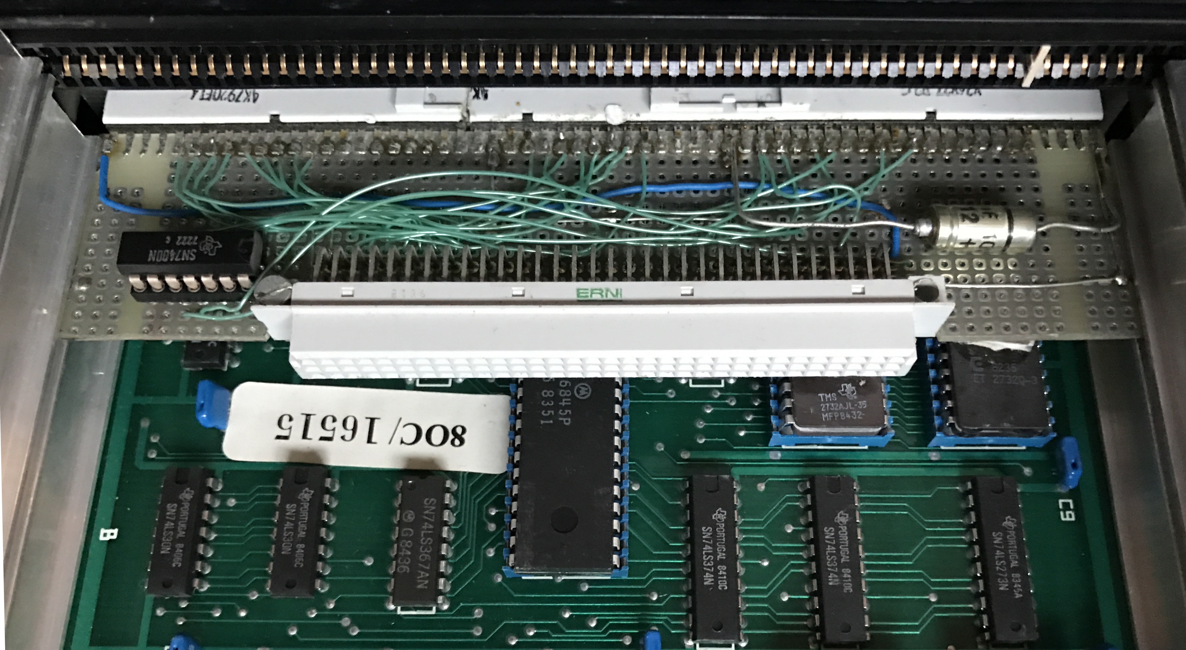
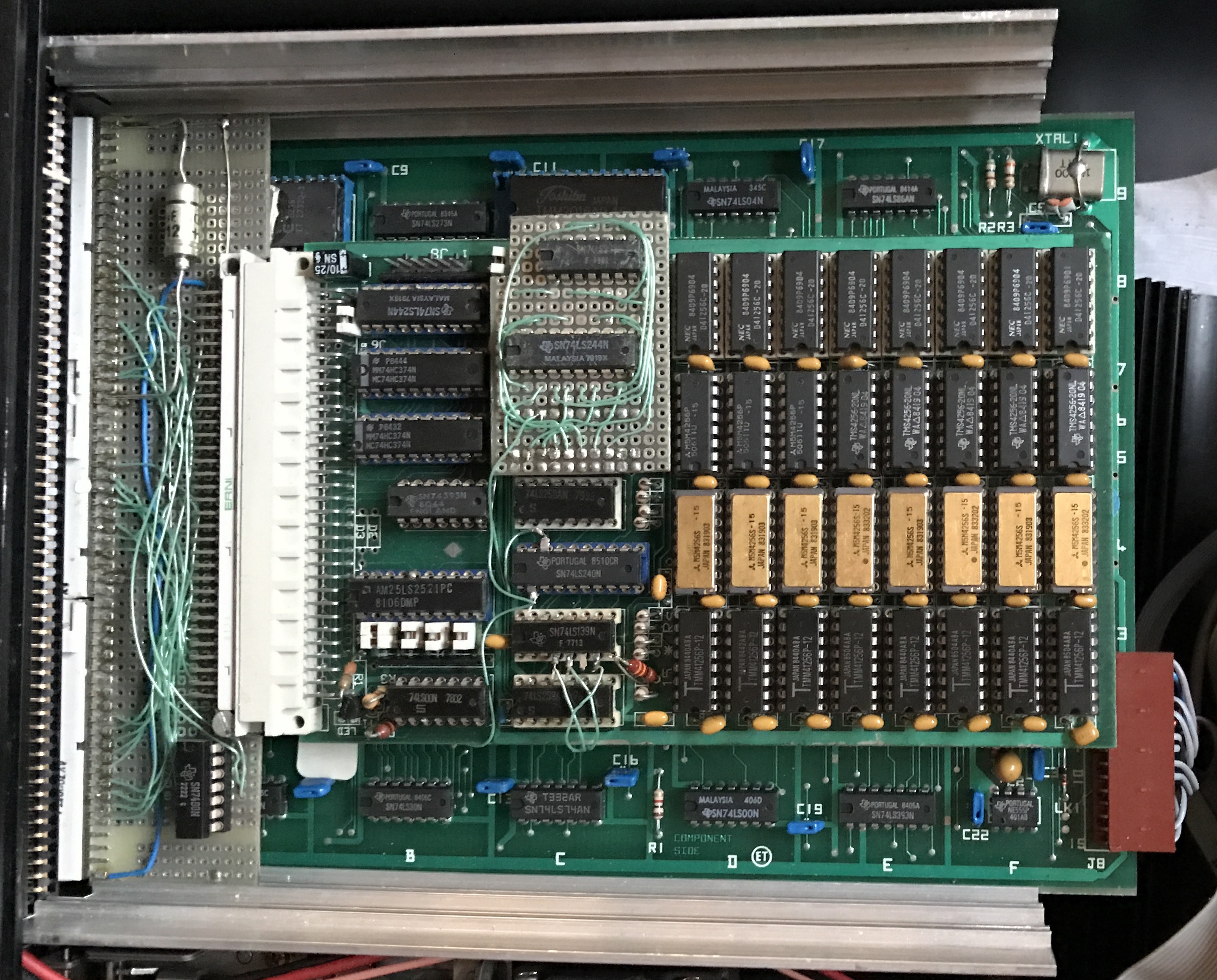
| With the FDX floppy disk controller removed,
you can see the Silicon Disk board installed in slot 2,
with the 80 Column board below it. |
 |
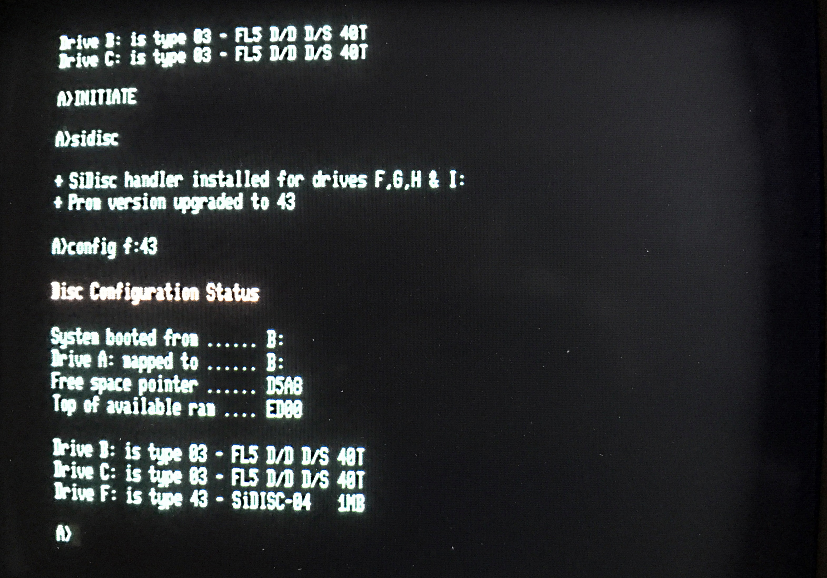
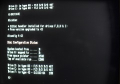
After running the FDX sidisc.com
silicon disk handler program and configuring the
disk as type 43, the system can see the 1MB disk
which can be formatted successfully. (The FDX
format program only checks
the first 64k of the RAM are working.)
Unfortunately, writing to the disk fails, hopefully,
the fault may just be one or more bad RAMs - to be
confirmed. |
 |
Replaced 3 x 258's
Replaced LS244
Replaced 2xHC374 with 2xHCT374
Replaced 74373
with LS373
Replaced all RAM with NEC 41256-150
Replaced LS240 with patch wires
Replaced LS139
with patch wires
Logic Chip testing with
TL866A
74LS00 OK
74LS258 OK (x3)
74LS245 OK
(Replaced original 'HCT')
74LS244 OK (Replaced
original)
74HCT374 (OK) (x2) (Replaced original
'HC')
74HCT393 (OK) (Replaced original 'LS')
|
|
|
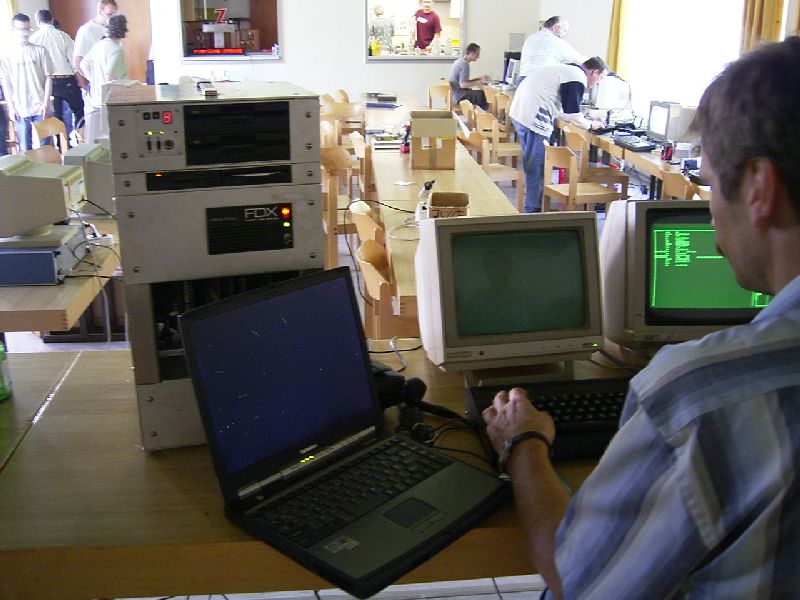
FDX Customisation - 2 |
FDX Advertised on eBay UK in June 2018
Has a user fitted Gotek USB drive running HxC
firmware.
A neat idea, but a better solution
is to use the Gotek with Keir Fraser's
FlashFloppy firmware like I did with one of my
FDXs. Read the details on
this page. |
 |
|
The French Connection |
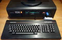
The next group
of photos are of an MTX512 from France.
The
machine is one of two obtained from Memotech's
French distributor by Gilles Bronchain.
|
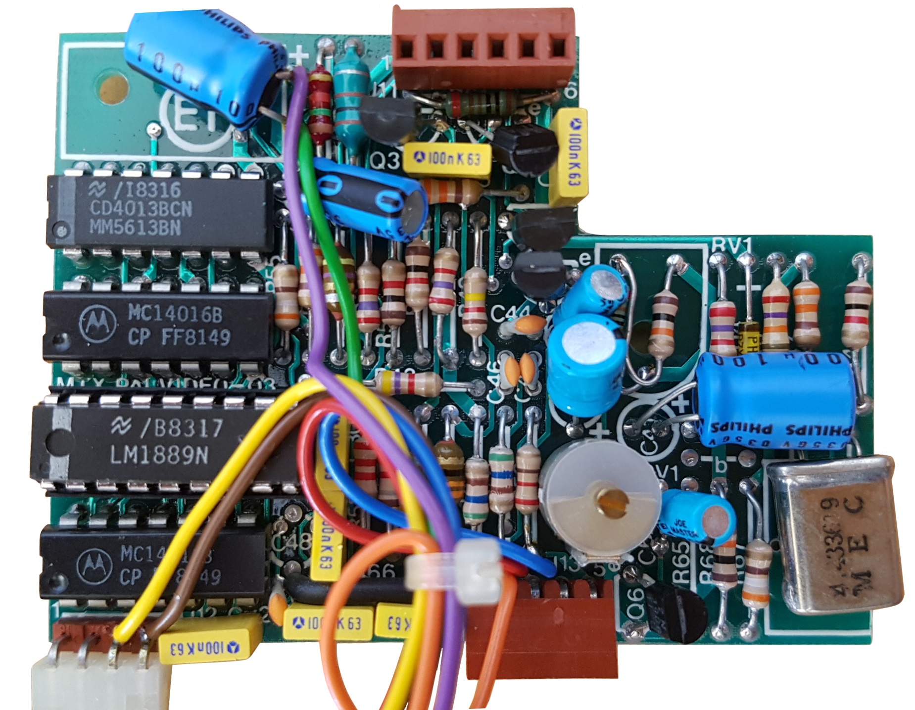
The machines have what appears to be a locally
made, custom PCB, that supplaments the MTX Composite
Video output with SCART RGB (probably).
The
brown plugs connect the MTX Video board to a SCART
converter PCB mounted inside the upper half of the
keyboard shell.
(Photos courtesy of Gilles
Bronchain, France) |
 |
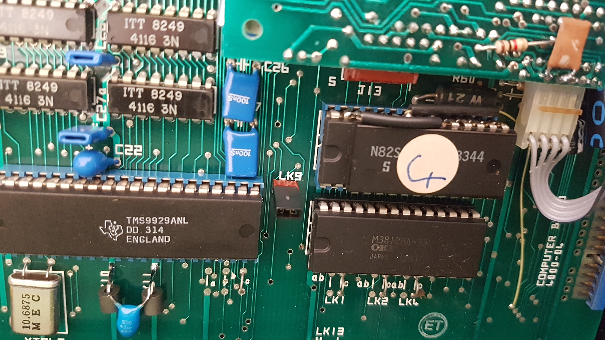
The Video PCB, removed from the MTX, showing
extra wires soldered to the board for the SCART PCB.
These wires are not taking modified signals from
the video PCB, they connect to the video and audio
signals on J13 from the VDP and sound chip on the
computer board.
The Purple and Green wires
are connected across capacitor C41, providing 5VDC
power for the SCART PCB. |
 |
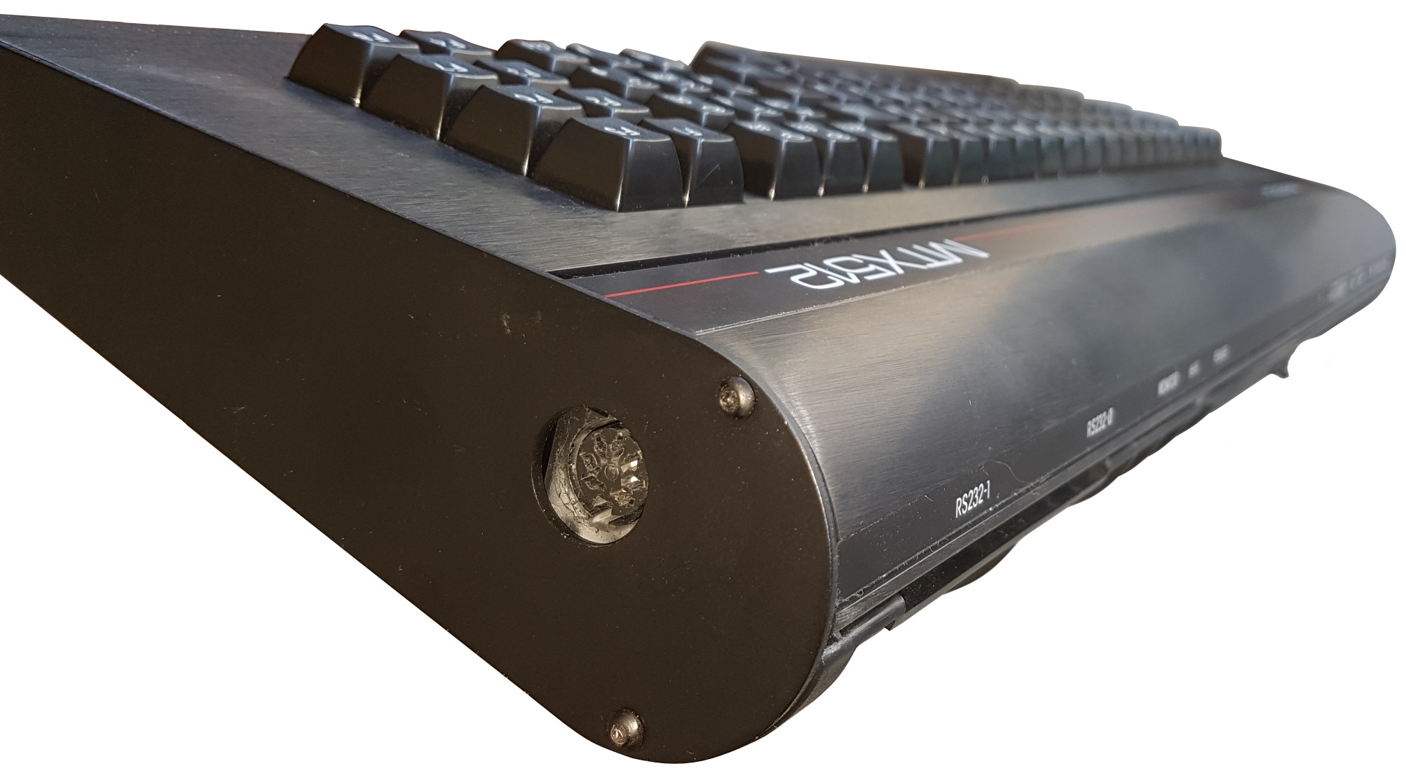
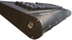
| A switch on the rear of the MTX is used to turn
the SCART output ON/OFF. (This switch is normally
used as the channel selector on US model MTXs). |
 |
| Tucked neatly in the space above the keyboard
PCB in the upper half of the MTX case, there is a
custom SCART PCB. There are no makers marks on the
PCB, so it does not appear to have been a Memotech
design. |
 |
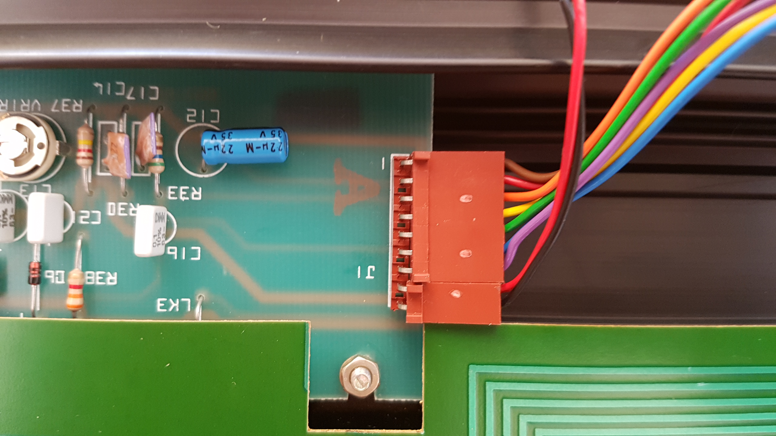
| Close up of the left hand side of the SCART PCB,
showing the red and black wires connected to the
switch on the rear panel and the 7 coloured wires
connected to the MTX video board. |
 |
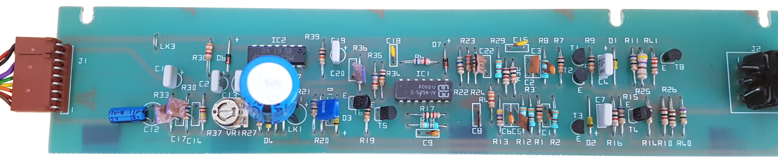
| The SCART PCB removed from the MTX |
 |
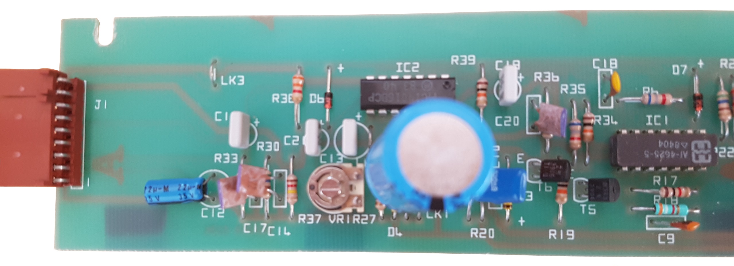
| A close up of the left hand side of the PCB |
 |
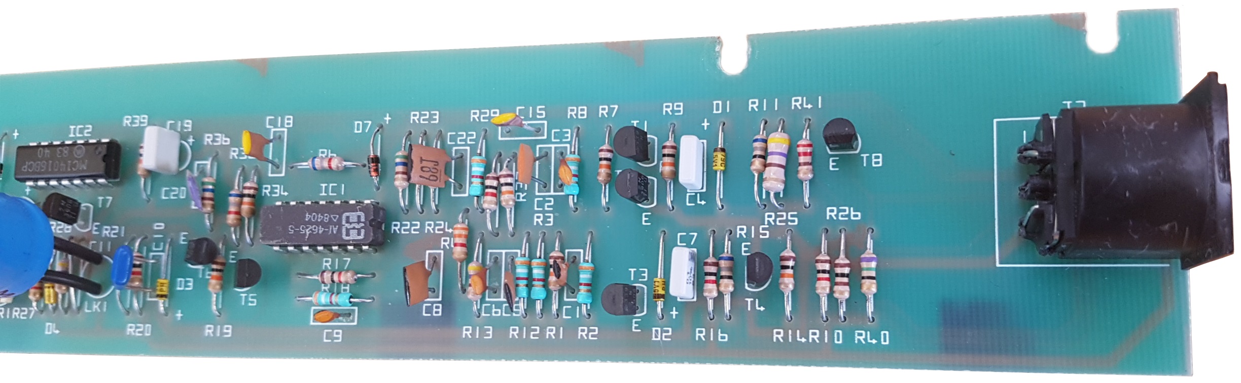
| Centre |
 |
| Right hand side |
 |
| A 7-pin DIN connector is soldered onto the SCART
PCB and the MTX end plate has had a hole drilled in
it to expose the connector. |
 |
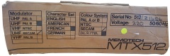
| The boxes for these MTXs are marked as French
SECAM as would be expected, but also contain
hand-written "PERITEL" (SCART) text - likely added
by the distributor. |
 |
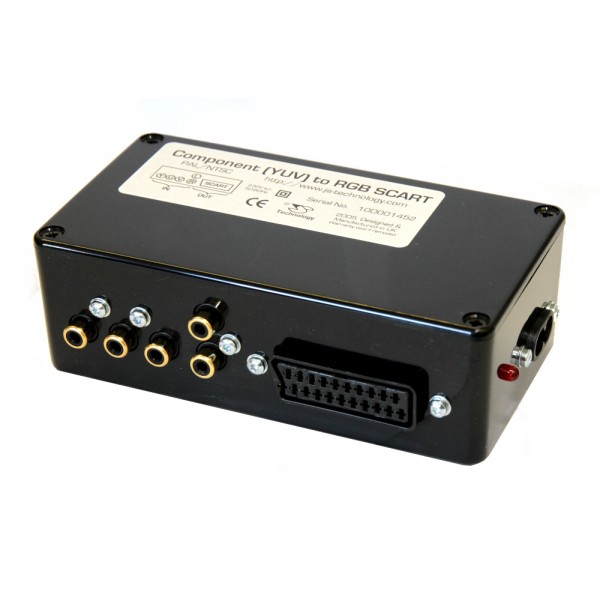
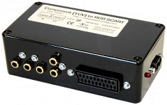
I would like to reverse engineer the "Memotech"
converter, but there appears to be an
"off-the-shelf"
converter that you could purchase from that
JS
Technology would do the job.
You would
need to add connections to the MTX Video board to
pick up the YUV signals in the same way as the "Memotech"
converter does.
NB : I have not
actually tried this converter. |
 |
The machine also has a piggy back language ROM
fitted.
The ROM is connected to the GROM line
and prevents external ROMs, such as Node or MAGROM,
from working with this machine. |
 |
| |
|
| |
|
| |
|