|
 |
The Memotech MTX Series |
 |
Video Wall "Reflex"
The Video Wall "Reflex"
The April 1990 issue of Lighting & Sound International,
available in the
Library pages,
describes the installation of a Memotech Video Wall as part of
the sound & lighting upgrades to the
Hammersmith Palais in 1990. The article briefly mentions the
"Reflex Touch Controller", this device allowed the
operator/DJ to "instantly access pre-programmed Video Wall
sequences using a 32 button keypad". Other that this reference, I
had been unable to find any other information about the
Reflex unit until I obtained a collection of Video Wall
hardware in 2013.
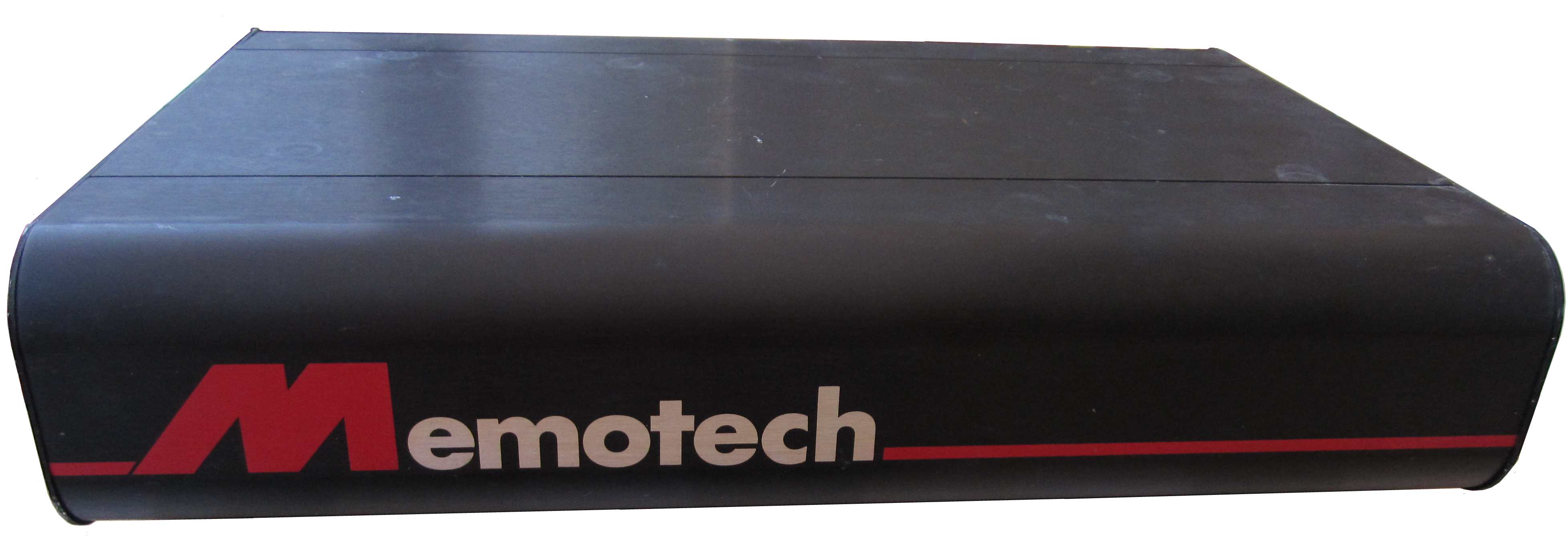
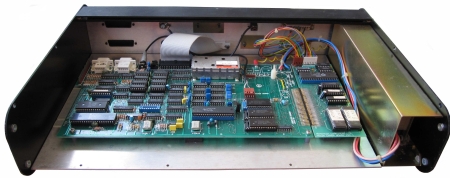
The photo at the top of the page shows one of the "black
boxes" in my Video
Wall bundle, this module has two Memotech labels on the
base, one identifying the module as a "10 x 1 Reflex",
the other marked "MTX2019R" - the same as the
model / serial number printed on the rear of the case.

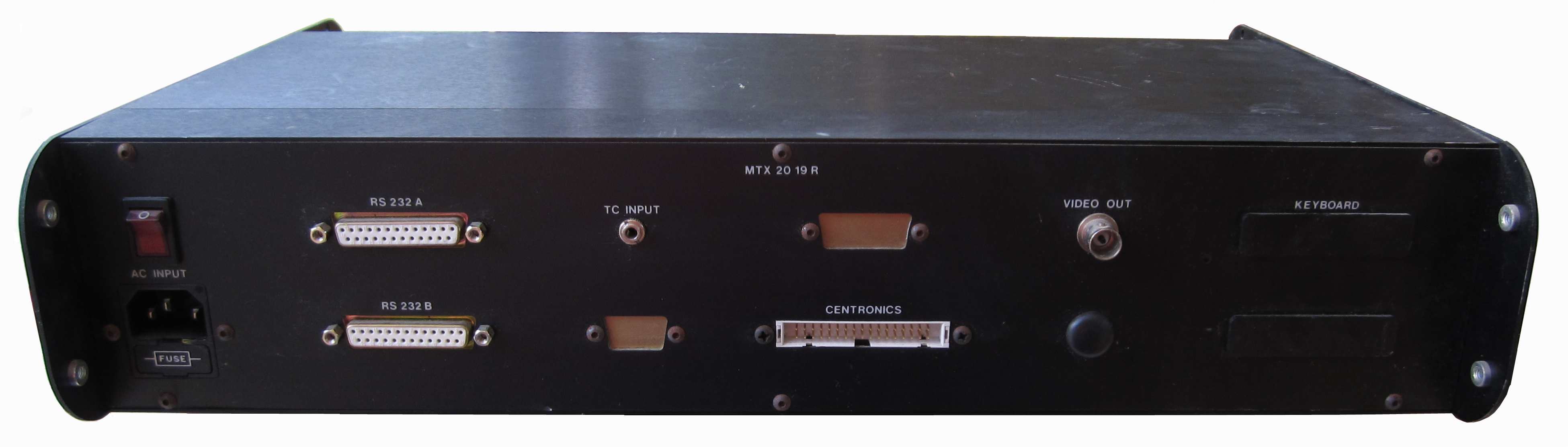
The rear of the Reflex unit
showing the input/output connections.
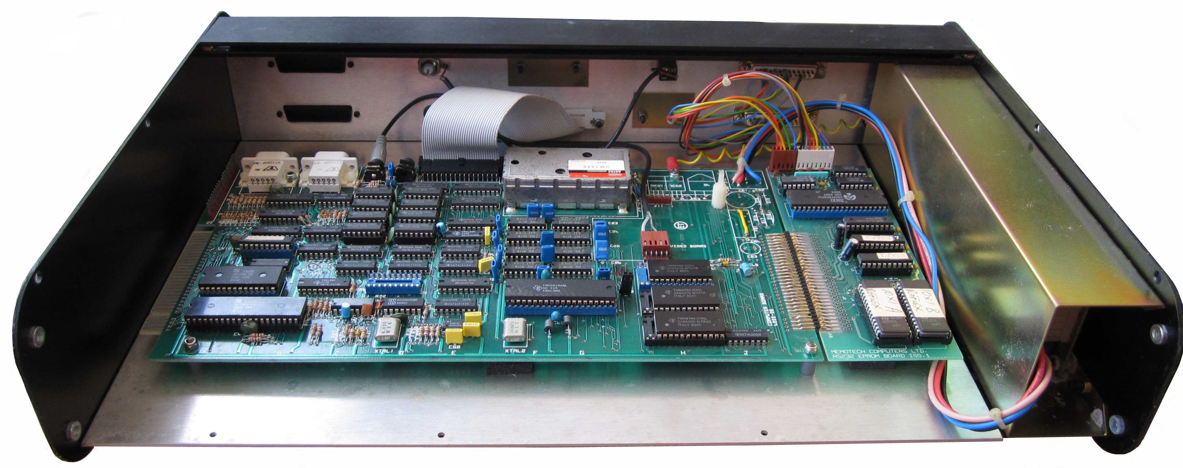
The Reflex unit was initially faulty - the PSU
had failed, making it necessary to open up the case, this
revealed how the Reflex system was put together :-
As the photo shows, at its heart is an MTX computer board
along with a board that I was previously unaware of - a combined
RS232 and ROM board.
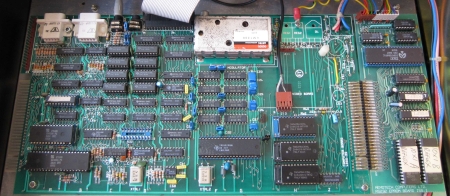
The majority of the standard MTX power regulation circuitry
has been omitted from the computer board and instead, the DC
voltages were provided by a
Skynet model number
SNP-3031 PSU, supplying +5V, +12V and -12V DC. The
-5V DC required for the Video RAM is supplied from the -12V
supply via the standard
MTX Zener diode, ZD3. The main-board RAM has been upgraded to
256kbytes in the same manner as an MTX512S2 and the Video
"daughter board" has not been installed. Modifications have been
made to the video circuitry to enable a monochrome composite
video signal to be taken directly from the TMS9929A video
display processor.
It can be see that the connectors on the rear panel interface
with the MTX and RS232 ports and we can deduce how the
Reflex system must have operated. The Reflex
has the key components that are installed in the MTX512S2 that
is also part of my Video
Wall equipment, i.e., a MTX computer with 256k of RAM and a
ROM card containing the Video Wall software making up a diskless
Video Wall system. The ROMs contained a copy of CP/M along with
the Video Wall software, when the system was powered on, it
booted CP/M, created a RAM disk using the memory in the MTX,
copied the software from ROM to RAM and started the Video Wall
program.
This Reflex supported a monochrome "prompt"
monitor through the BNC "Video Out" connector, an external
EBU/SMPTE
Time Code input connected to the MTX "Ear" port through the
"TC Input" 3.5mm jack socket and enabled control the Video Wall DDFS
through the MTX Centronics port through the Reflex
Centronics connector. The rear panel has a blank connector
labelled "Keyboard" which could have been cabled to the MTX
keyboard header if an external keyboard was required, but as
this is not fitted, the Video Wall would have to have been
controlled using a "remote". Andy
Key recalls that there was small keypad used with some Video
Wall systems. Unfortunately, my system is missing this separate
keypad.
The Memotech
Video Wall Product Description on the
Manuals page describes how a
Video Wall system could be controlled using commands over an
RS232 serial link. With no keyboard connector fitted, this
Reflex unit could only have been controlled via the RS232
connector - this is likely how a Reflex Touch Controller
was interfaced to the Video Wall system.
As I was unable to repair the failed PSU and the SNP-3031 is
obsolete, I spent a while trying to find a low cost replacement
solution, perhaps using a PC "micro" PSU. I did not manage to
find an alternative PSU that matched the voltage/current ratings
of the SNP-3031 that could be fitted into the case without some
difficulty, but I did find that the replacement Skynet product,
the SNP-9031 is still available and at reasonable cost, so
purchased a new one.
|
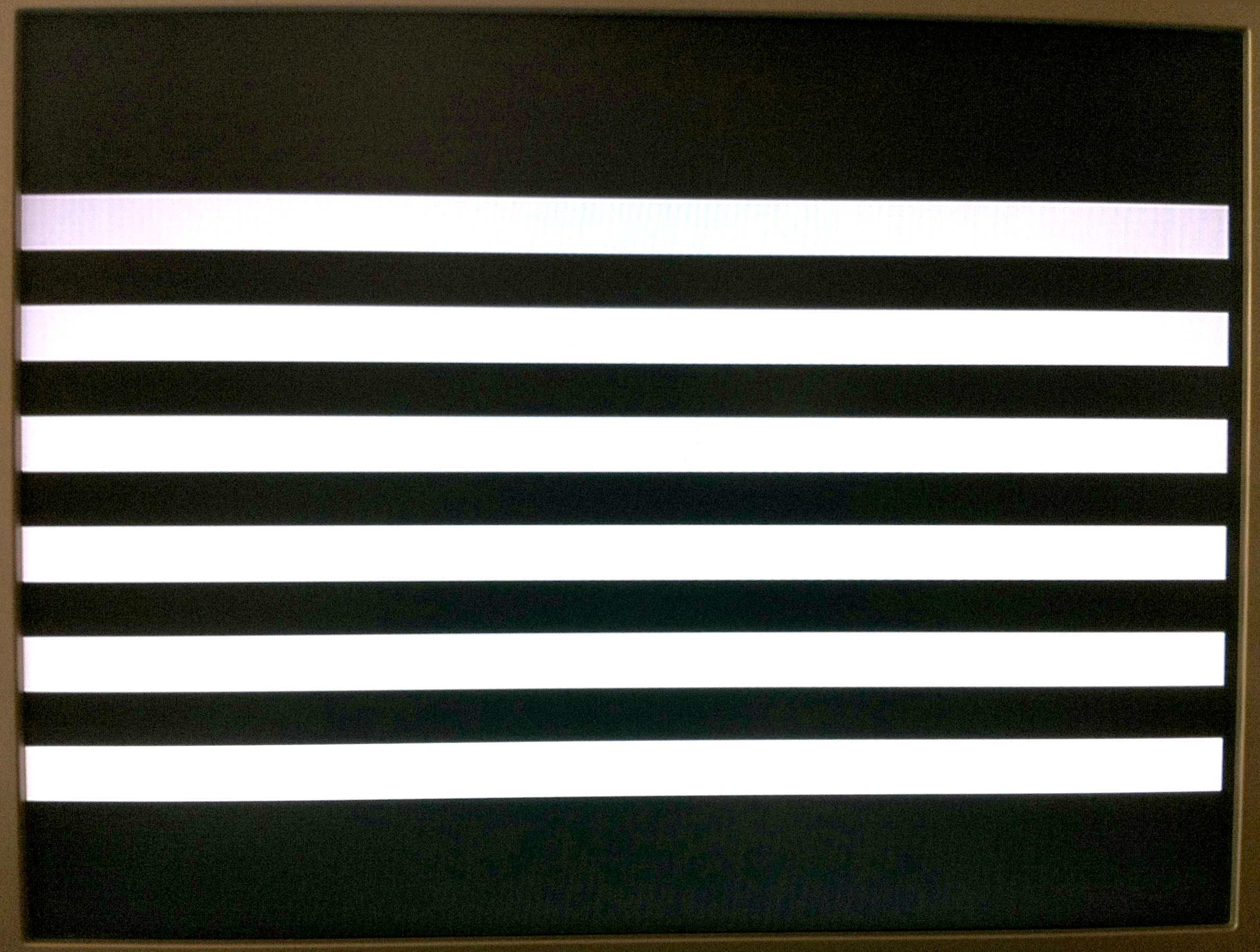
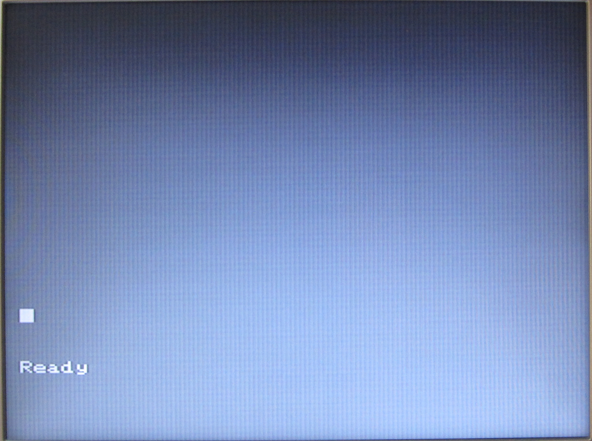
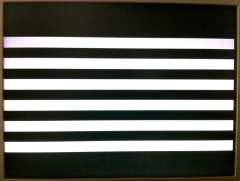
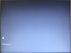
After installing the new PSU, checking the voltages
and powering up the Reflex, I was confronted with
this screen display on the prompt monitor. Obviously, the unit still had
a problem and needed further investigation to
determine whether there was just a video display
problem or whether there were more serious faults
present. |
 |
I removed the ROM board Video Wall ROMs and
tried to boot the MTX from its standard ROMs, this was
unsuccessful, it resulted in a solid black display, although
without the horizontal white lines. I tried various things, including
installing the Reflex MTX computer
board ROMs in another MTX, where they operated normally, as well as swapping out the CPU, CTC
and VDP - again, with no improvement.
I was able to take a dump of the Video Wall
ROMs that
Andy
was able to interpret and extract the start-up configuration
and provide the following details :-
The first ROM is an 8KB RSCPM boot ROM
followed by the first 56KB of initial RAM disk content
and the second ROM is the next 64KB of that initial RAM
disk content An RSCPM is the combination
of an SCPM ROM (using 56 column VDP text)
and RCPM ROM (copying ROM to RAM disc).
[Details of how the RSCPM boot ROMs work can be found on
this page on Andy's site.]
After booting CP/M, the STARTUP command
would execute "VS108R F8\F1", which
would run the "VS108R" program an pass simulated
keystrokes "F8" and "F1" to
it.
The Video Wall Product Description helps us
decode the meaning of the start up string :
| VS108R |
|
Id. |
Meaning |
| VS |
Program name prefix, "VS" is
unusual, it would normally be "VW" |
| 10 |
Software Version, in this case,
Version 10 |
| 8 |
Video Wall Size, in this case 8
x 8 |
| R |
Control option, in this case,
"Remote" control |
|
Program Start-up String |
| F8 |
Special Options Menu |
| F1 |
Enter Remote Mode |
The Video Wall software in the ROM would
therefore appear to suggest that this Reflex
was intended to control a very large Video Wall system,
consisting of an 8 x 8 matrix of 64 screens.
The
Cameron Video Wall User Manual contains information on
the commands used by an earlier version (5.x) of the Video
Wall software, it is believed that later software versions,
including version 10.x installed in the Refelx ROM would not
have made significant changes to the user commands.
|
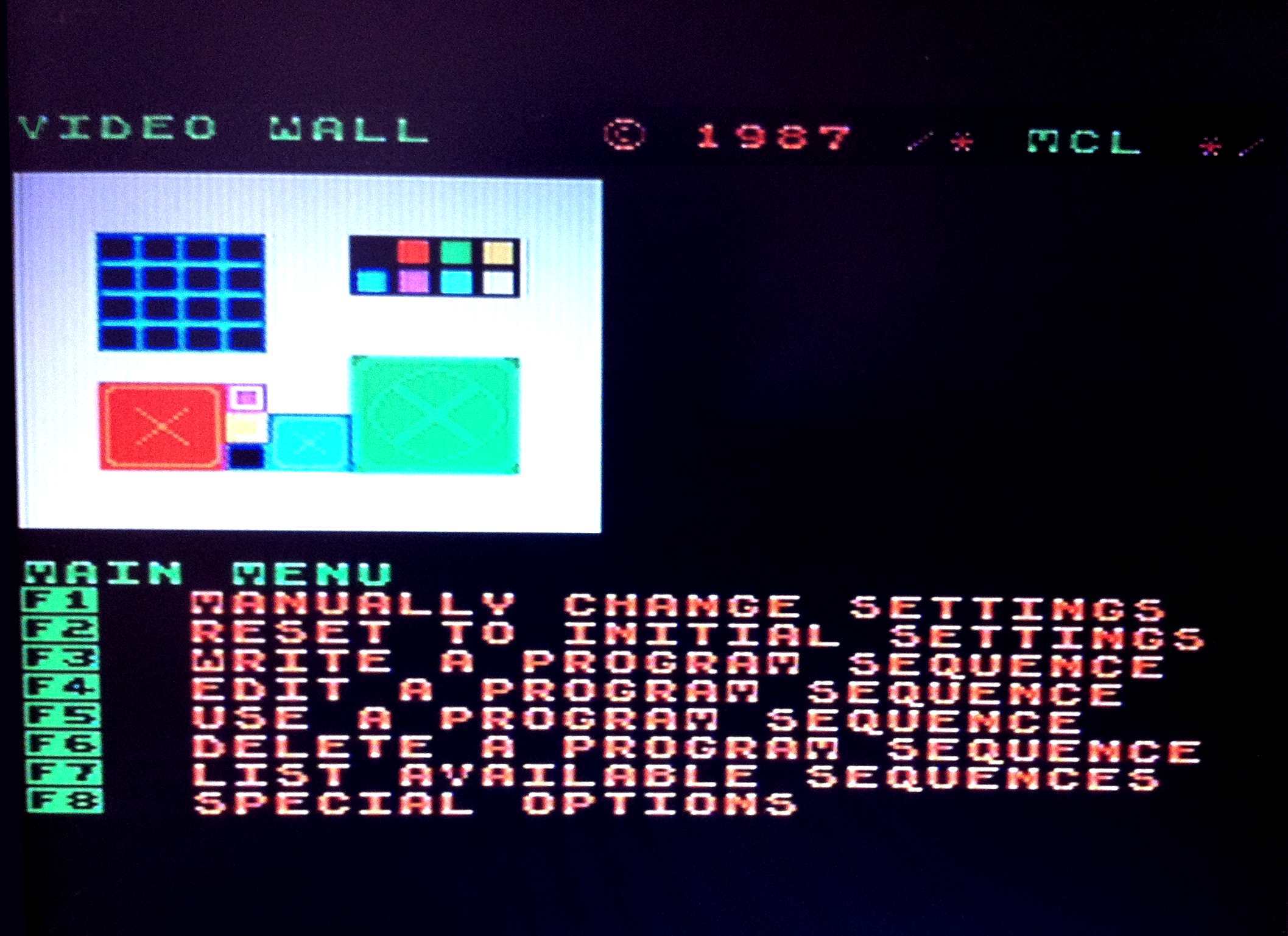
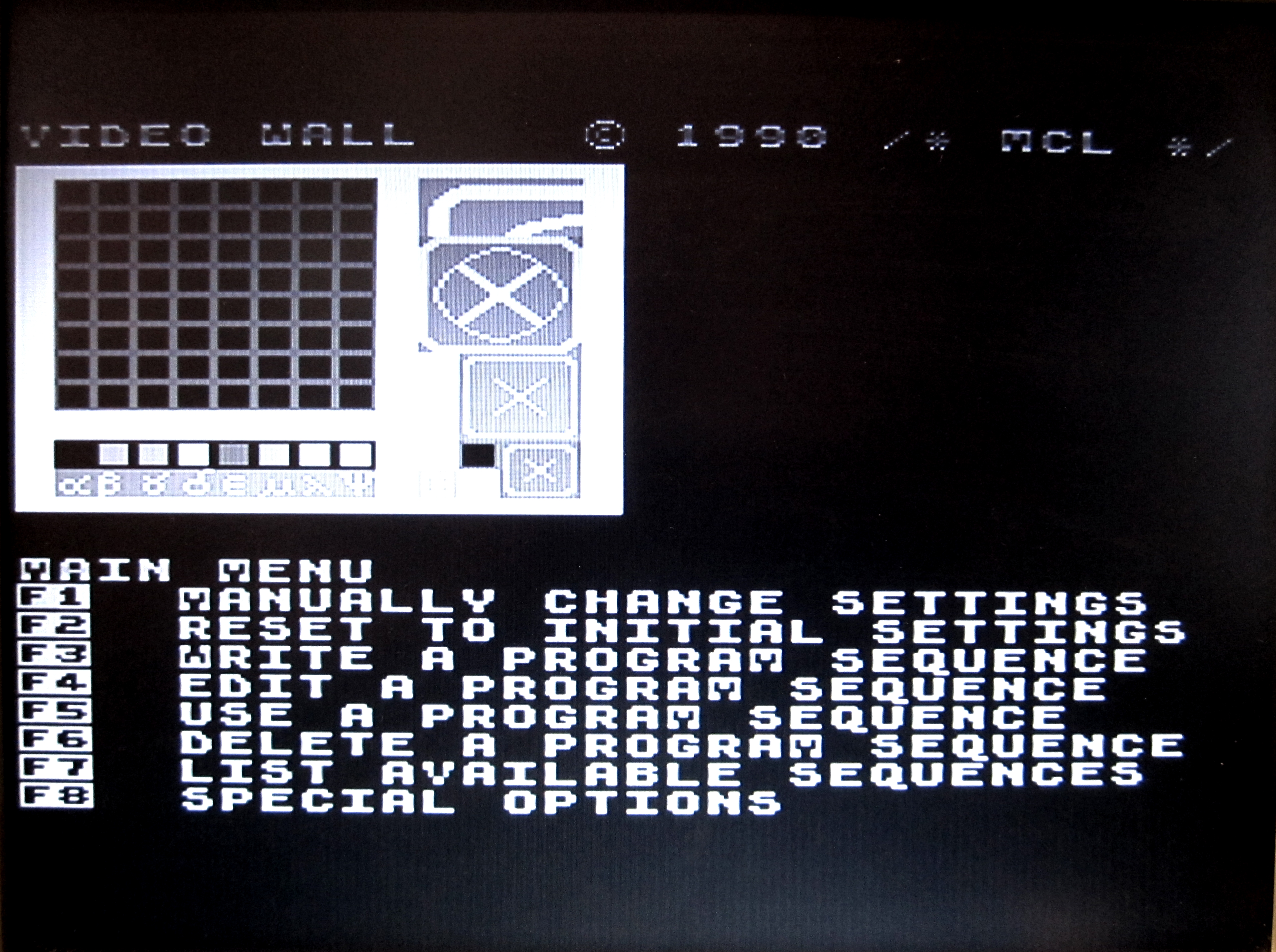
When started interactively, the
Video Wall software would initially display a Main
Menu similar to that shown here, loaded from the ROM
of my MTX512S2 Video Wall computer.
Entered manually or on the start-up
command line, "F8" would invoke the "Special
Options" selection of the Menu, subsequently, "F1"
on the "Special Options" menu would put the Video
Wall software into "remote" mode. |
 |
The Cameron manual states that "Remote" mode
was not included in Version 5.x of the Video Wall software,
but "remote" mode is described in the Video Wall Product
Description. In remote mode , commands to control the Video
Wall through the operator interface, e.g., MTX computer or
Reflex controller, would be received on serial port "A".
To try to determine whether the Reflex
was operating at any level, I reinstalled the Video Wall
ROMs and connected a terminal emulator to the serial port
and tried to enter commands to "take control" of the system
and issue commands over the remote link. The Reflex did
not respond to any enquiry or control sequences over the
serial port, I took this to be a good indication that the
software was
not actually running. (When the Reflex was eventually
working, I discovered that this conclusion was incorrect -
without the DDFS(s) connected to the Reflex, the software
reports a "NO SYNC"
error, does not
enter remote mode and waits for an operator to hit the "ESC"
key.)
Since the software did not appear to be
running with the Video Wall ROMs installed and the screen
output from the normal MTX ROMs was a solid black display,
the symptoms were suggestive of typical MTX
RAM problems, which often result in a pure black
screen with a constant audible tone, although in this case, the
system has no sound output capability (sound is
normally passed through the Video board).
Fortunately, the RAM on 256k MTX
computer boards is installed in sockets, and whilst I
did not have any replacement RAMs that I could use
for testing, I was able to remove all of the
on-board RAM and install
one of
Andy Key's
external
MTX RAM cards.
|
With the Video Wall ROMs removed and the external
RAM card connected, the MTX started up and displayed
the usual MTX "Ready" prompt, although
it was obviously in monochrome. |
 |
|
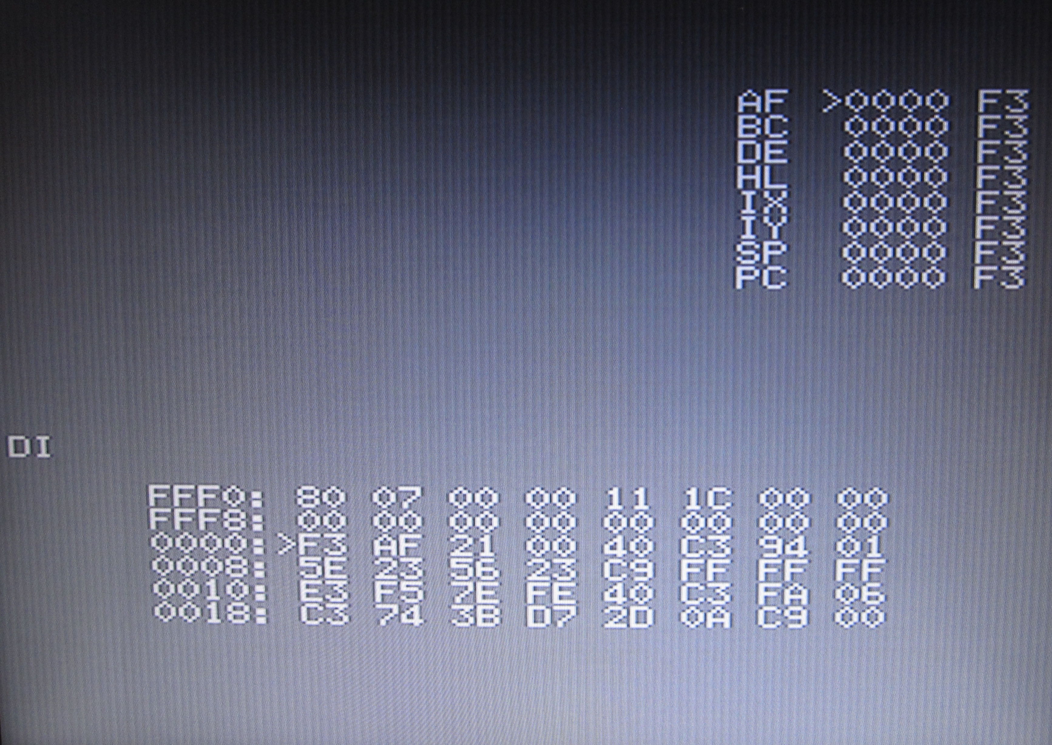
Connecting a standard MTX keyboard to the computer
board connector, the system operated in normal MTX
40 column mode and I was able to enter BASIC, use
PANEL etc., demonstrating that the main computer
board was now working correctly using the external
RAM board. |
 |
|
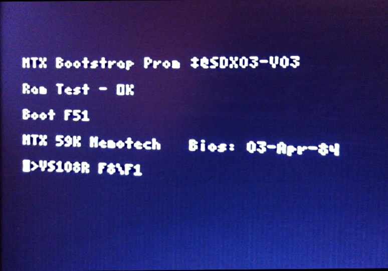
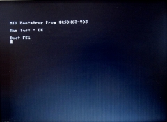
With the
Video Wall ROMs re-installed, the system now started
up in 56 column RSCPM mode, displayed
the PROM bootstrap message, executed and passed the
standard 64k memory test, but then hung.
The RAM
card was only pinned to provide 64k of memory to the
system, allowing it to pass the base 64k memory
test, but resulting in failure when it tried to
create the RAM disk for the Video Wall software. |
 |
|
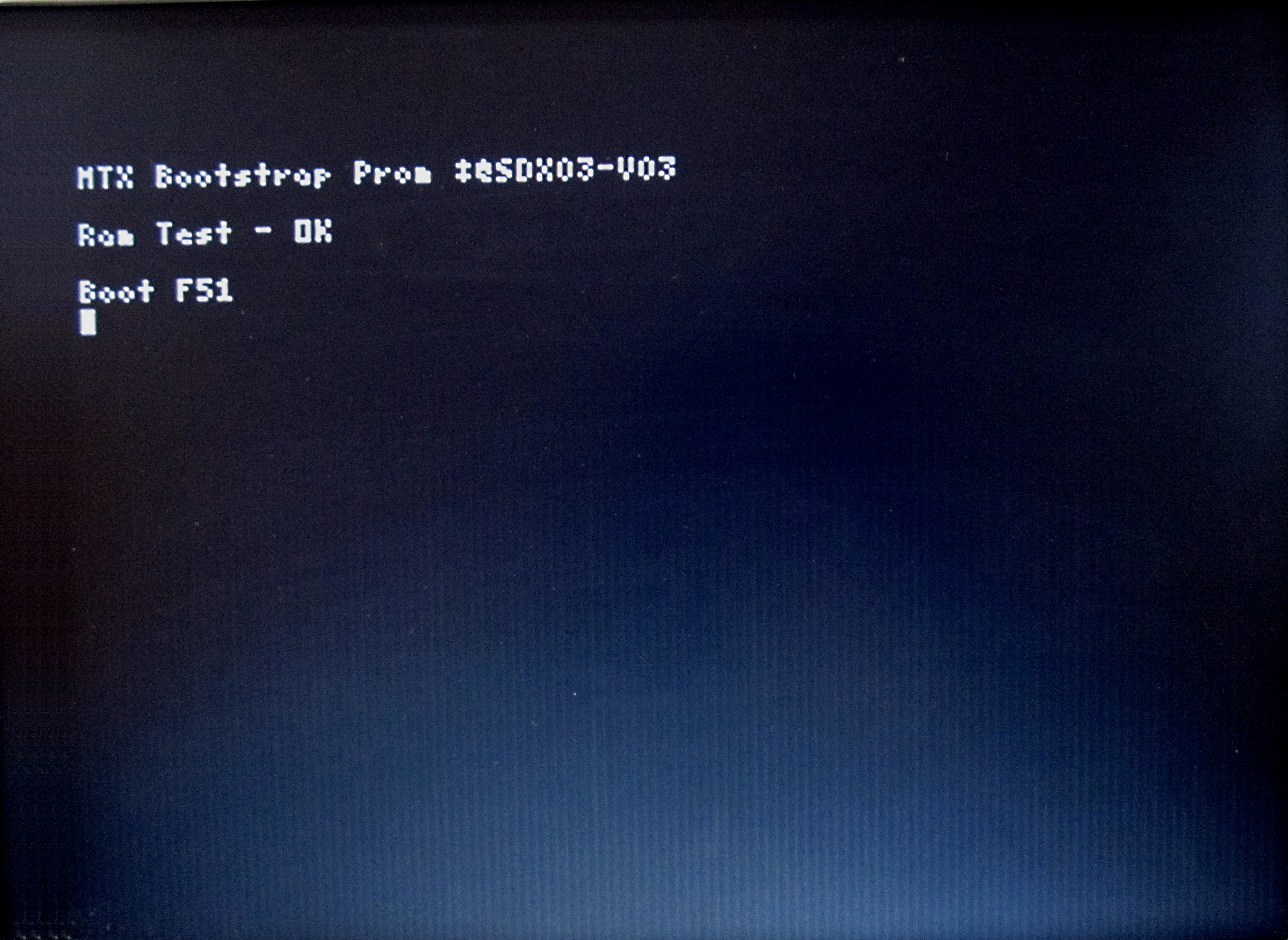
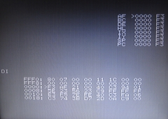
After re-pinning the RAM card to provide 512k of
memory, the system was able to configure the RAM
disk and start up the Video Wall software. As with
my other Video Wall MTX512S2, the CP/M start-up
screen is only displayed for the briefest of moment -
making it difficult to capture., but displaying the
messages shown in this poor quality image! |
 |
|
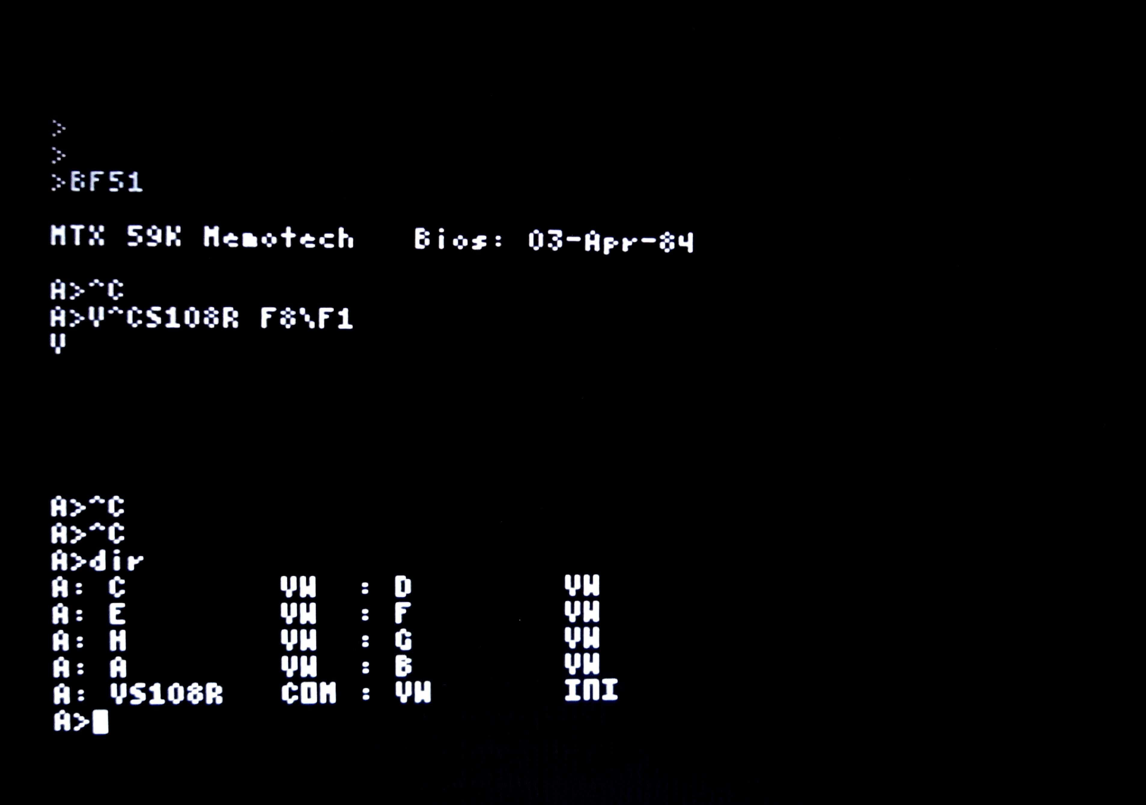
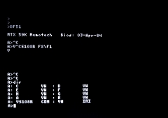
If you are very quick, you can hit <ctrl><c>
between the Boot F51 message being
displayed and the Video Wall software being loaded
to interrupt the start-up sequence and gain access
to the CP/M A> prompt. This is of
limited use, but you can see the Video Wall software
program and sequence file names on the RAM disk.. |
 |
|
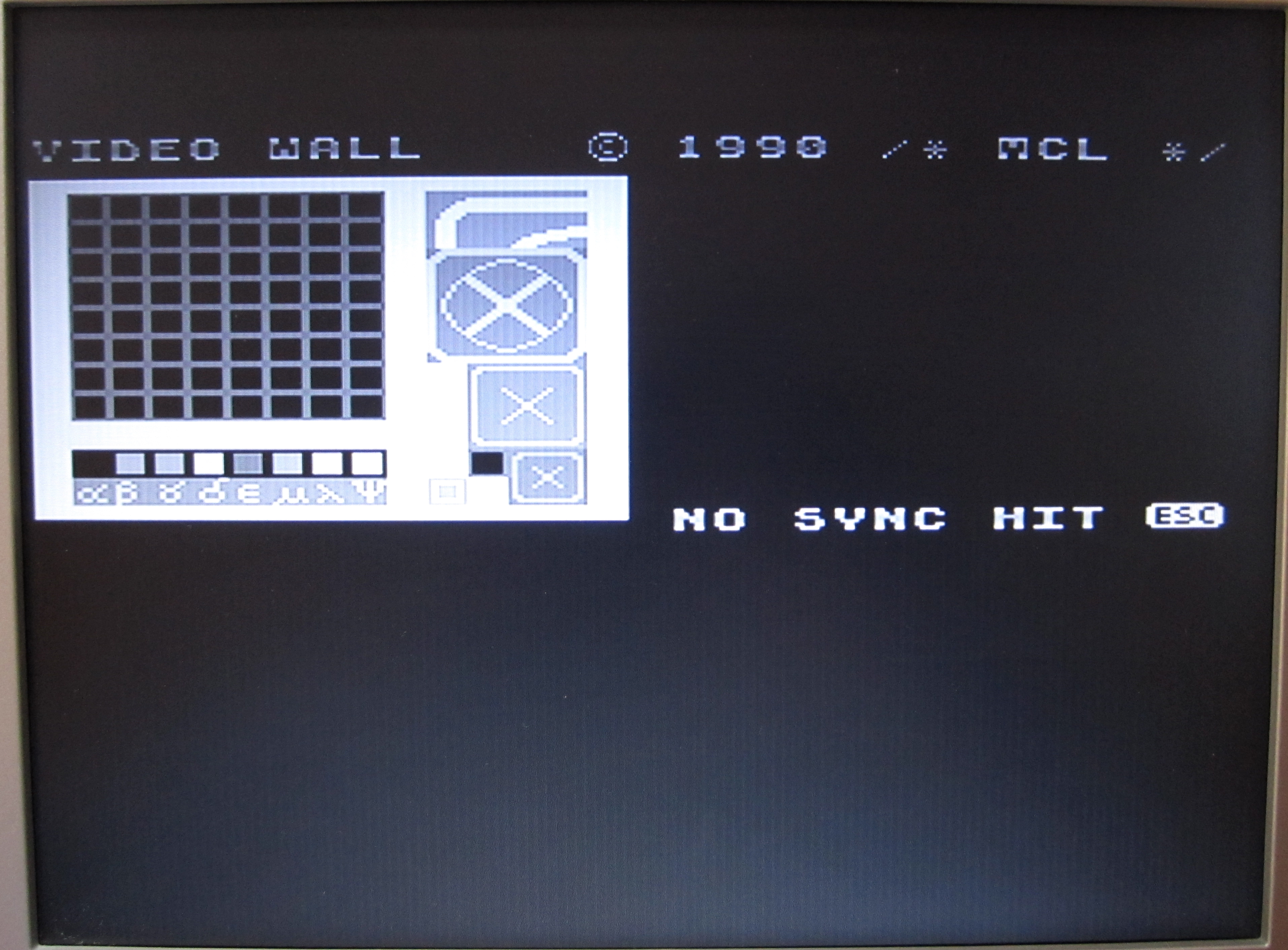
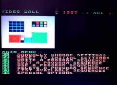
The video display quickly switches to 40 column mode
and displays the Video Wall Main Menu graphic - the
screen layout confirming that this system was indeed
intended to control a 8 x 8 screen Video Wall.
With no DDFS(s) connected, the "HIT (ESC)" prompt
remains on the screen until the operator responds -
if there is a keyboard present. With my test setup,
I still had an MTX keyboard connected. |
 |
|
After hitting <ESC>,
the normal Video Wall software menu is displayed.
The F8 key brings up the "Special
Options" Menu, from where the Remote
mode can be manually enabled.
|
 |
|
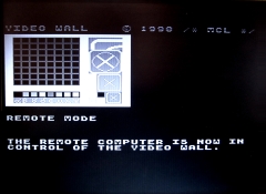
If Remote mode is enabled, either
manually, or automatically by the start-up command
string, a message to that effect is displayed on the
prompt monitor. |
 |
With the Reflex now functional, the final step will be to repopulate the
on-board RAM sockets with replacement memory - as the internal
photo shows, there is no room inside the Reflex module to allow
the RAM board to be permanently installed.
Whilst I am pleased to have a functional Reflex
unit, it is evident that I do not have the remainder of the
hardware required to construct a 64 screen Video Wall - that
would require 8 DDFS units and I have only one, confirming that
I appear to have a selection of various items of Video Wall
hardware, rather than a single Video Wall system.
Return to Video Wall Overview
|