|
"MTX Plus+" -
I/O Board
Introduction
The basic functionality of the I/O board will include
keyboard, parallel printer and RS-232 serial interfaces, largely
based on the MTX computer design, as well as the decode logic
for the I/O ports on the board. The MTX uses a Z80 DART
(Dual-Channel Asynchronous Receiver/Transmitter), clocked at
4MHz, to provide the RS232 interfaces, the original intention
was that MTXPlus+ would also use a DART, clocked at 4MHz to
drive the serial ports. However, it became clear that the DART
needs to be clocked at the same frequency as the CPU, so this
would not have been acceptable for the 16MHz clock speed of
MTXPlus+.
Since the Z80 DART is only available in NMOS versions with
maximum clock speeds up to 6MHz, for MTXPlus+, the Z80 DART will be replaced with
the more versatile Z80 SIO (Serial Input/Output
Controller). CMOS versions of the SIO
are available with clock speeds up to 10MHz, still
below the intended clock rate (16MHz) of the
computer, but, the
encouraging results that we have
seen with over-clocking CMOS Z80 CPUs made us
optimistic that a 10MHz SIO would be reliable at
16MHz - time will tell!
The design also includes an
8255
Programmable Peripheral Interface (PPI) chip, to provide an
IDE interface for a
Compact
Flash "drive". (Additional information about the IDE
interface can be found on the
Notes page.)
The MTX keyboard interface will require the use of the
keyboard from an MTX computer, this is fine for Martin and I,
who can "borrow" keyboards from our MTX computers, but this is
probably not an option for anyone else interested in building
their own MTXPlus+. To allow the design to support
the use of non-MTX keyboards, the board will include a new
interface to enable the computer to use a standard PS/2
keyboard. To maintain compatibility with the MTX, the PS/2
interface will need to convert the PS/2 key scan codes to the
MTX keyboard drive/sense line I/O signals using I/O ports 5 and
6.
The provisional design for the PS/2 keyboard interface uses a
pair of Altera MAX7000
CPLDs as used on the MTXPlus+
CPU board, for much the
same reasons as one is used on that board. The interface will be
based on the same principles as
Andy Key's keyboard
interface for
ColecoVision, along with some of the VHDL in Andy's
REMEMOTECH - a faithful replica of the Memotech MTX/FDX/SDX
hardware running in the
FPGA on an
Altera DE1 "Development and Education" Board.
In a similar way to how we did the CPU prototype boards,
Martin and I will be using slightly different approaches for the
basic I/O board and keyboard interface. Martin's board
will use the 74HC same keyboard interface components whilst I
intend to try and fit all of the MTX like, discrete logic, into
the CPLDs.
Design & Build
|
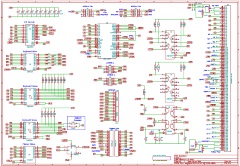
The draft
schematic for the I/O board, including twin CPLDs
that I plan to use to do conversion between
a PS/2 keyboard scan codes and the drive/sense port
values that an MTX computer expects to see.
The
schematic also includes an alternative
implementation using discrete ICs for the I/O decode
logic and I/O port interface chips for the board
that Martin will be building.
Connection to the peripherals will be via headers at
the edge of the board |
 |
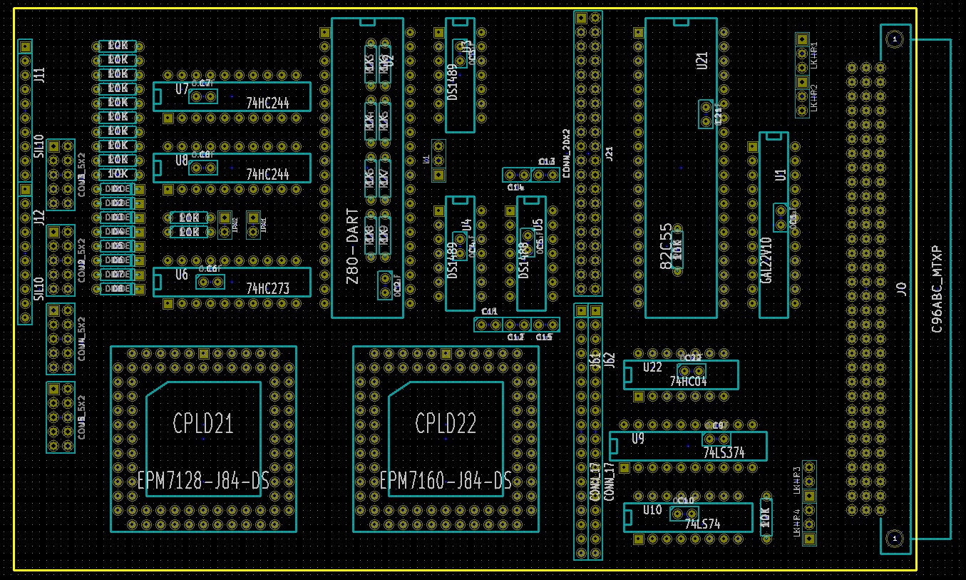
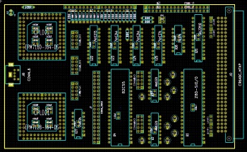
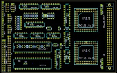
| Initial layout of the twin CPLD
board, at this stage, I was mainly focused on making
sure that the intended components would fit the
board and that the I/O port headers were accessible
from the front edge. Although this
layout was feasible and the components were loosely
grouped by I/O device, it was not well suited to a
phased construction and all of the wiring would need
to cross over the CPLDs. |
 |
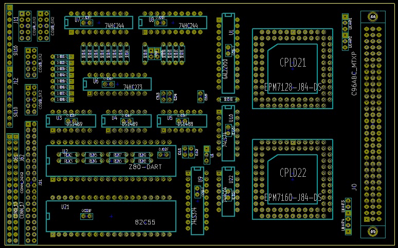
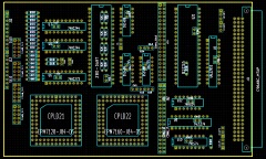
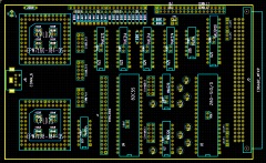
| The second incarnation of the
layout, this board has the components more clearly
split into zones and the CPLDs better separated from
the other components.
The 4 ICs in the upper centre of the board are
the SIO and support chips for 2 x RS232 ports,
using the same hardware as the MTX RS232 board.
Typical of designs of the day, MTX serial ports
needed +/- 12V DC supplies to drive the ports at
typical RS232 voltage levels. |
 |
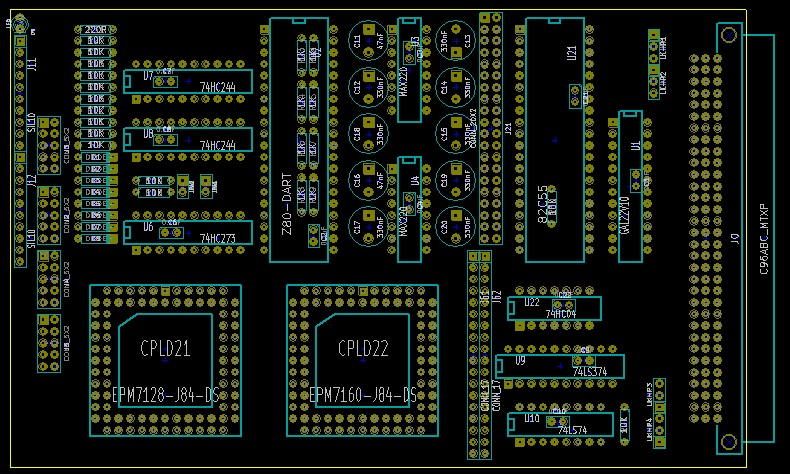
| To eliminate the need for +/- 12
volts on the board, the legacy DS1488 and DS1489
have been replaced with 2 x MAX232 chips from Lez.
This IC has internal charge pumps that generate
RS232 compatible + /-10 volt lines from +5V, to do
this, they each need 5 electrolytic capacitors. Due to
the extra space required for the capacitors, 2 x
MAX232s will be used to provide one fully RS232
compatible port with handshaking (like MTX Port B)
and one port that uses the TTL voltages from the
DART. |
 |
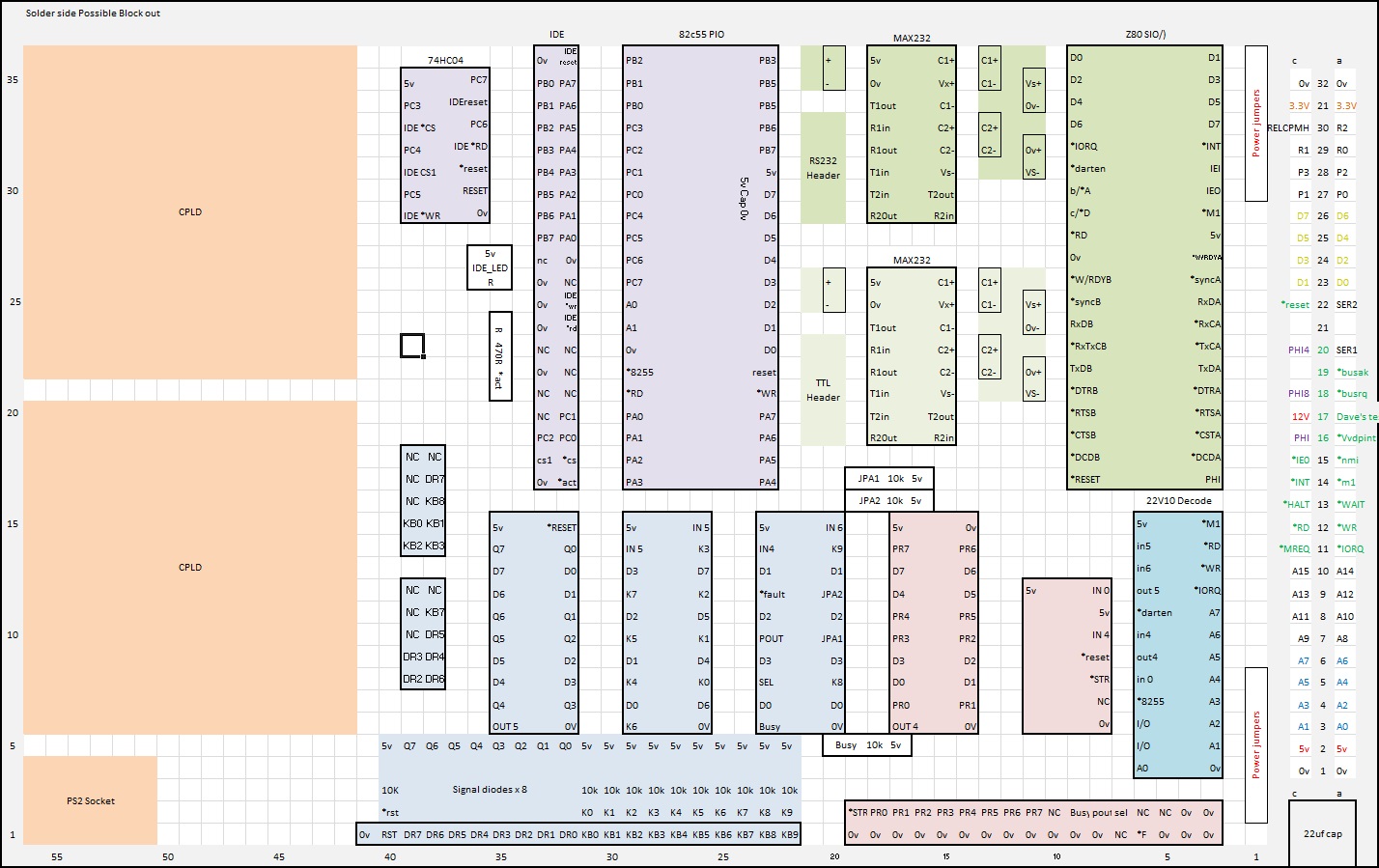
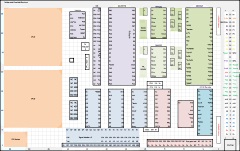
| After discussing various options,
Martin's draft board layout looked like this. (Note:
Martin's layouts are from the wiring side
perspective) The squares at the left hand side are
areas "blocked out" where the CPLDs and PS/2
keyboard connector will be placed on my board. The
layout allows both the CPLD and MTX hardware
components to be placed, allowing me the flexibility
to add the components from the older design should
they be required. |
 |
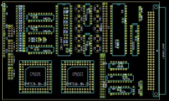
| My version of the "final" layout, I
have moved the CPLDs and PS/2 socket around a
little, but the two layouts are essentially the
same. Martin's prototype boards have a slightly
different matrix than mine - being 1 hole wider and
1 hole shorter. |
 |
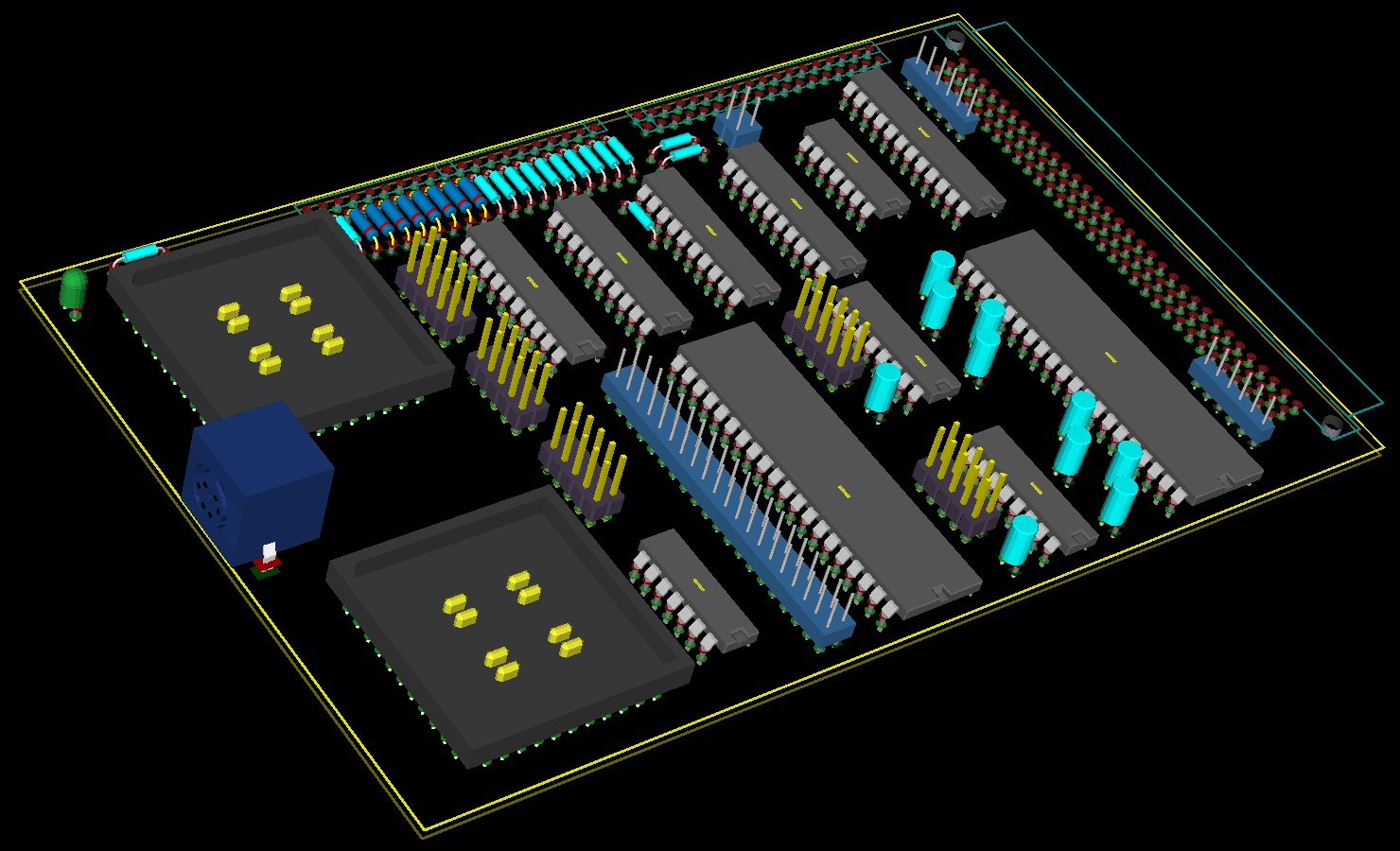
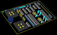
| KiCad / PCBNew 3d model of the draft
design |
 |
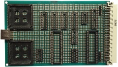
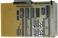
| My Board, with the sockets for the
major components placed to check the fit and ensure
that sufficient space was left for the passive
components and headers for the I/O devices. As
seems to be the norm for MTXPlus+, the board will be
pretty "busy" again, but should be build-able. |
 |
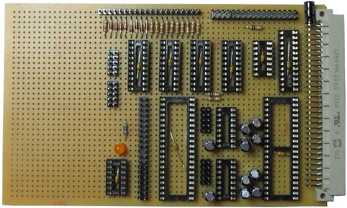
| Martin's board, with the passives in
place. |
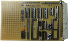 |
| With a minimum set of components to
installed to allow the system to be tested,
including the keyboard and printer interfaces. |
 |
| Wiring side of Martin's board. |
 |
| Can you tell what is is yet ? Yup
- the Memotech MTX ROM running on Martin's MTXPlus+
hardware. Things are looking good, a minor error in
the keyboard I/O port decode logic meant that keystrokes
were not being recognised, but that was quickly
fixed.
Hopefully, I can press on and catch up before
Christmas. |
 |
| The first BASIC program on MTXPlus+
In the foreground, you can just about make out
Martin's DIY matrix keyboard driving the computer -
although missing keycaps or other identification
makes typing somewhat difficult !
(My board is getting there, still quite a lot of
wiring to do) |
 |
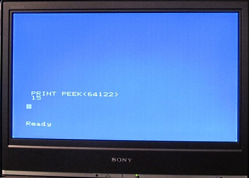
|
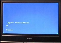
Proving
that MTX BASIC can see 512K of RAM . . . . .
PRINT PEEK(64122) returns 15, i.e., 15+1
x 32K pages = 512KB
Just
waiting for Martin's first 512KB BASIC program now .
. . . . .
(Martin
has two 512K SRAMs on his CPU board, the maximum
useable in non-ROM, i.e., CP/M mode is 784KB) |
 |
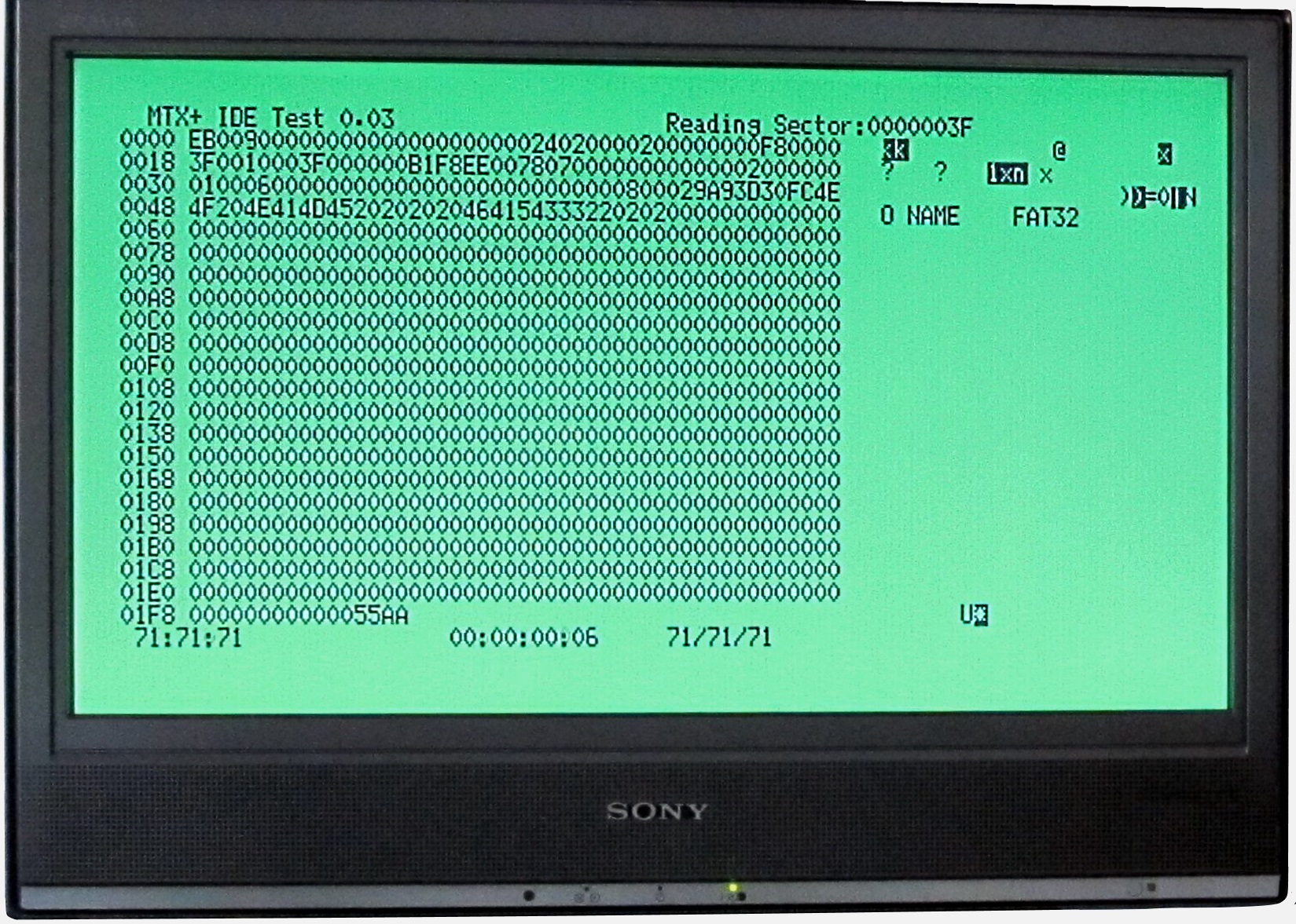
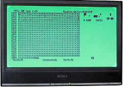
| While I was lagging behind wiring my
I/O board, Martin was able to start testing the
IDE/CF interface by creating another of his test
ROMs.
This is Version 0.3 of his IDE test code, the
display shows a dump of the boot sector of the FAT32
partition on the 8gig drive. |
 |
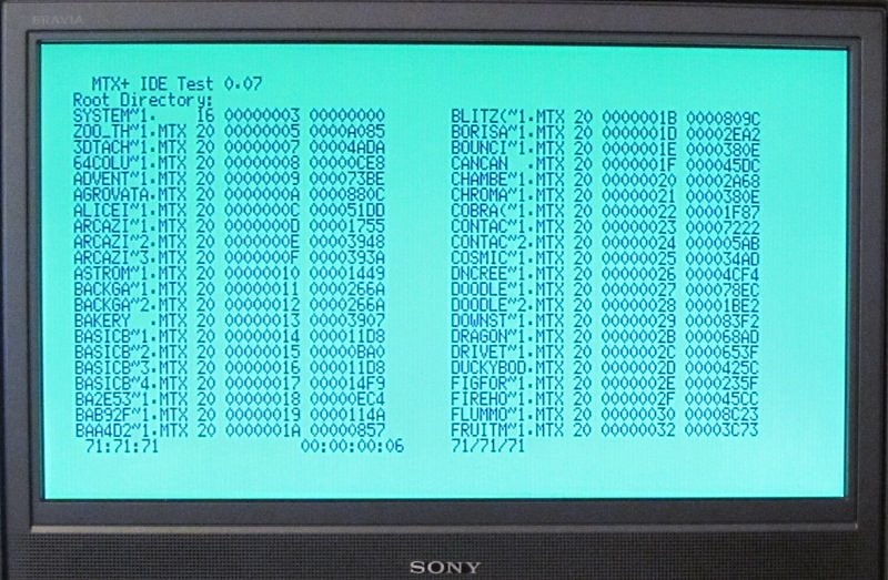
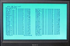
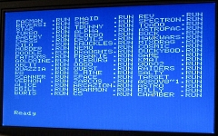
| Now up to Version 0.7, this is the
output from Martin's CF test ROM displaying multiple
filenames from the root directory of the card. If
you open the full size picture, you should recognise
the filenames as some of the .mtx files that we have
in the software
library, displayed here with DOS 8.3 format
filenames. |
 |
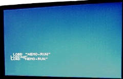
| Still a work in
progress, but Martin is making real progress with
integrating the CF into the MTXPlus+ ROM (the actual
CF code will be in the support ROM and called from
the patched MTX ROM).
This video shows a ".RUN" file for Nemo
being loaded from MTX BASIC - it is just a little
faster than from a tape - don't blink, or
you'll miss it :-) |
 |
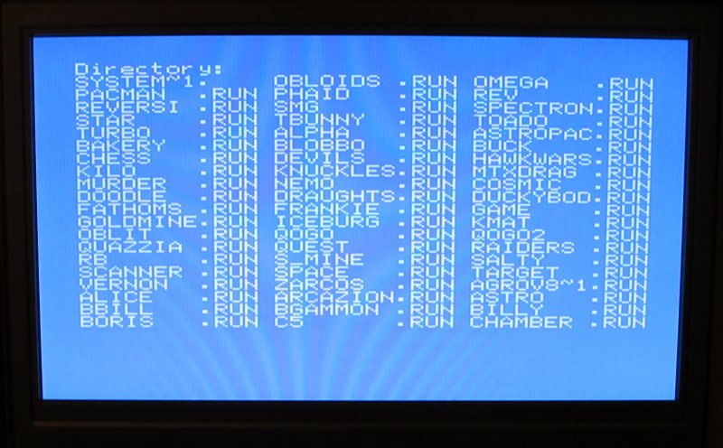
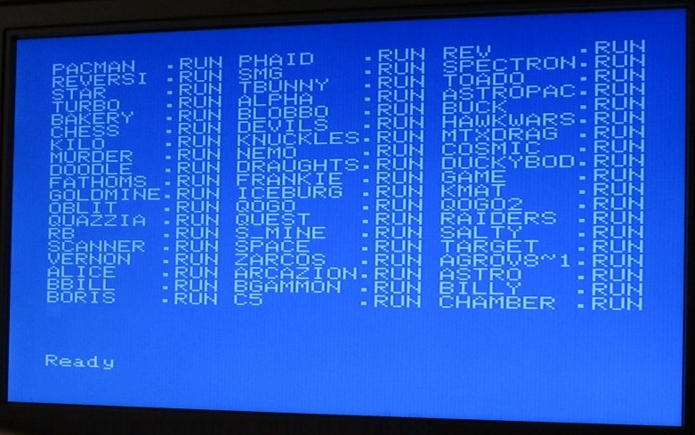
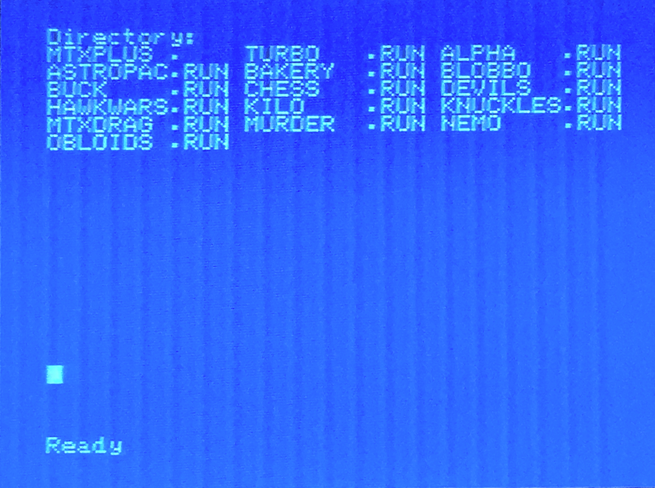
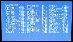
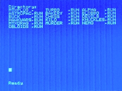
| Another update on Martin's CF ROM
code . . . . This picture is Martin's MTXPlus+
"Turbo" displaying a directory listing for the CF
card in response to a modified MTX BASIC LOAD ""
command.
(Patching the LOAD command requires less
modification to the original MTX ROM than adding a
"DIR" command to MTX BASIC) |
 |
| As the "LOAD" command does not
normally return to BASIC, the directory listing
would crash to PANEL when it was completed.
Martin has modified the code so that the
directory listing will return to the MTX BASIC
"Ready" prompt |
 |
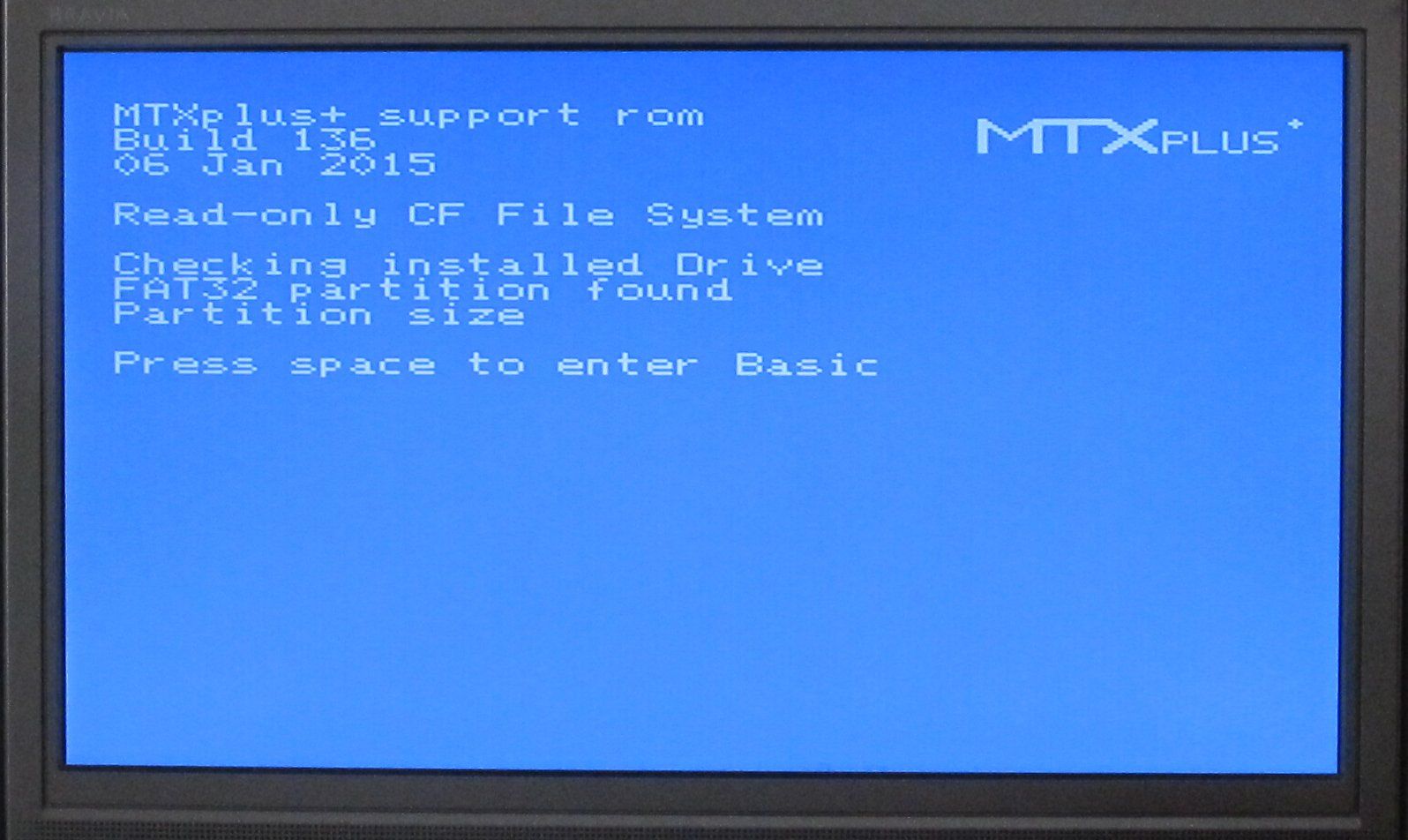
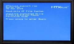
| Martin modified the code to
initialise the CF drive at start-up, with the ROM
then looking for the CF at boot time, a check was
added to ensure that the drive and card were
present. Leading to a new Boot Screen for MTXPlus+
- a nice touch. |
 |
| I have finally finished wiring my
I/O board ! My board is way more complex than it
needed to be, but it incorporates all of the
components to test the three main hardware options
:-
- Discrete logic chips, like Martin's board,
MTX type matrix keyboard input
- 2 x Altera EPM71xxS CPLDs replacing the
discrete chips, MTX type matrix keyboard input
- 2 x Altera EPM71xxS CPLDs replacing the
discrete chips, PS/2 keyboard interface
The board is laid out with the components in 5
zones :-
- keyboard passives (resistors & diodes),
keyboard, joystick and printer headers
- the CPLD area with the two CPLDs and JTAG
interface header (see notes page for extra info)
- MTX512 keyboard and printer I/O port decode
GAL and interface components
- Serial port hardware : Z80 SIO, 2 x MAX232s
and 2 x serial port headers
- IDE/CF port hardware : 82C55 PPI, Hex
inverter and IDE interface header
With the zoned board layout, I had intended to
build the board in stages, starting with either the
CPLD or discrete logic components required to
connect a keyboard and add the other components
later. When I started building though, it became
clear that it would be better to wire up all of the
components at one time, rather than try to add
components and connections later. This took me quite
a bit longer than I anticipated and meant that I
slipped quite a way behind Martin - still, by the
time I catch up, I'm sure that he will have written
software to use the CF interface ! I made a couple of minor changes during the
build, including, replacing the standard PS/2
keyboard connector with a header block. If I do put
the system in a case, it will be better to have the
PS/2 connector attached to the case, rather than the
front of the I/O board. Some IDE devices,
including the CF cards that we are using, are able
to receive power via pin 20 of the interface so I
connected a fused 5V line to pin 20 of the IDE
connector - the fuse holder is located on the front
of the board between the two PLCC-84 sockets.
Note : due to space constraints over the holiday
period, I did not have my system attached to a
decent TV/monitor. The screen images below were
taken using my iPhone from my cheap 7" composite
monitor. |
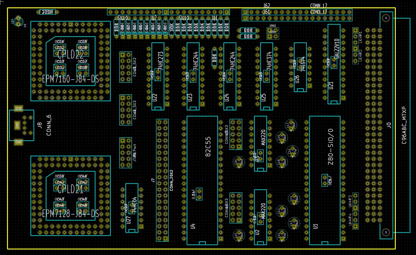
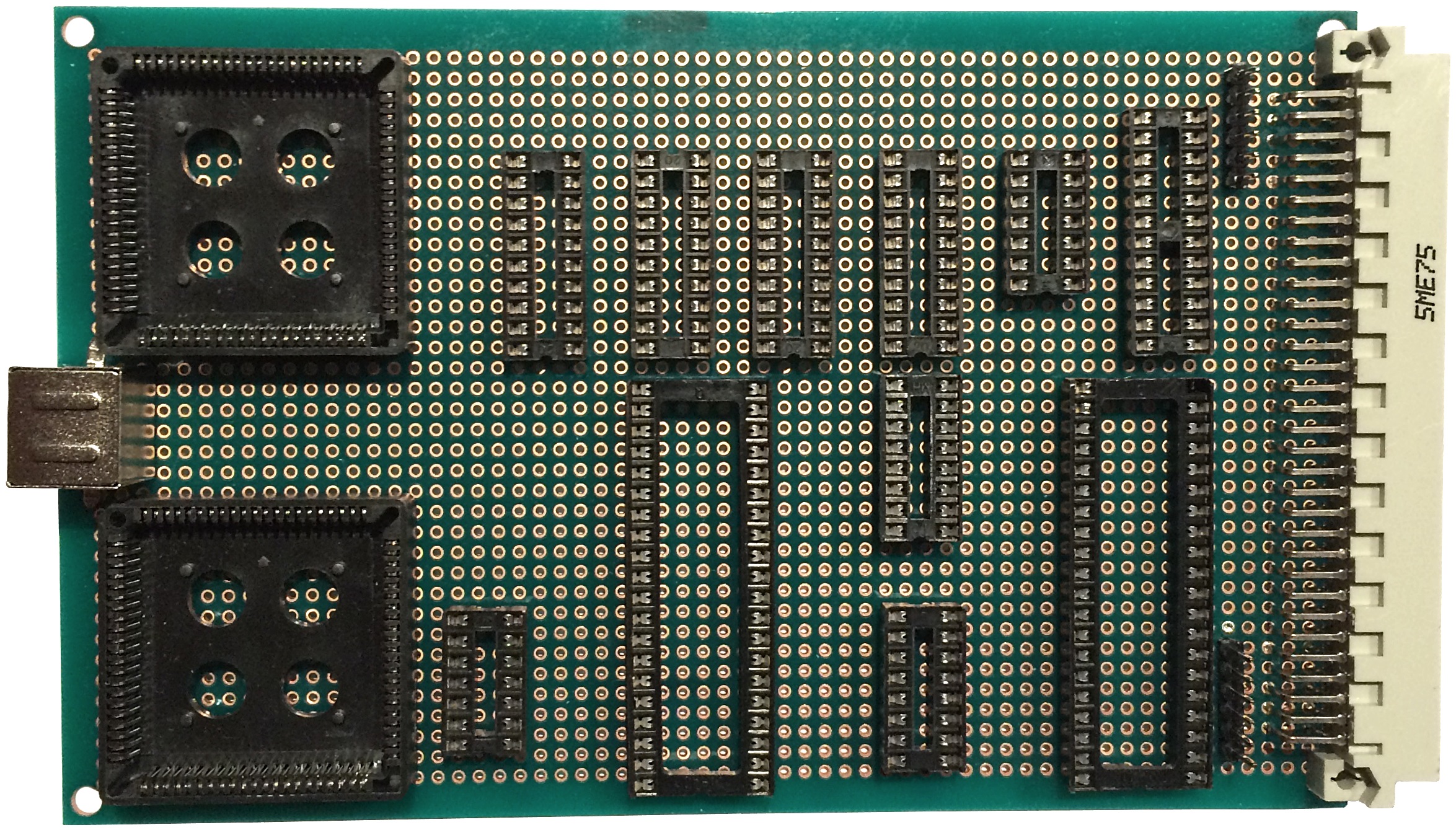
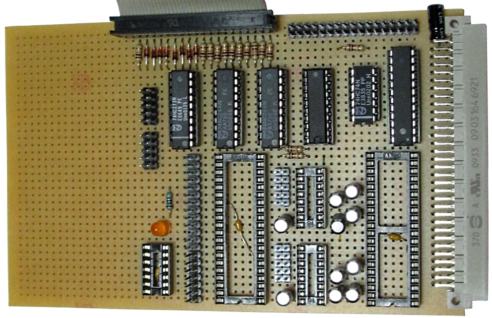
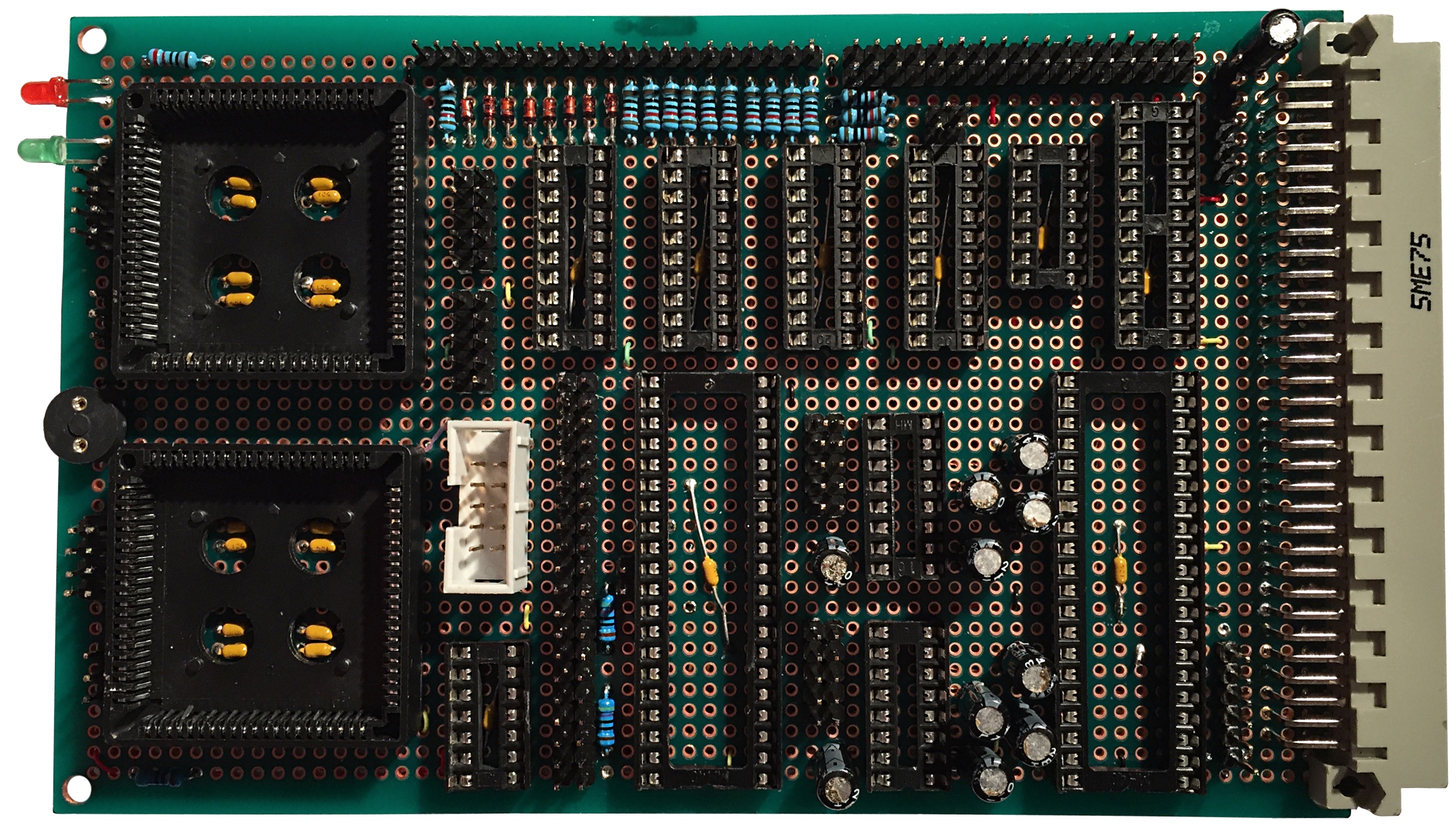
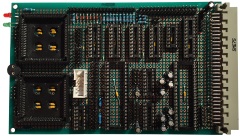
| "As built" layout of my I/O board.
The white IDC socket is for the
JTAG interface used to program the CPLDs.
Ideally, both CPLDs will be permanently connected to
the JTAG lines, but each can be disconnected using
the jumpers at the front of the board. (For
additional details, see the
Notes page.) Only limited connectivity testing had been done
at this point. |
 |
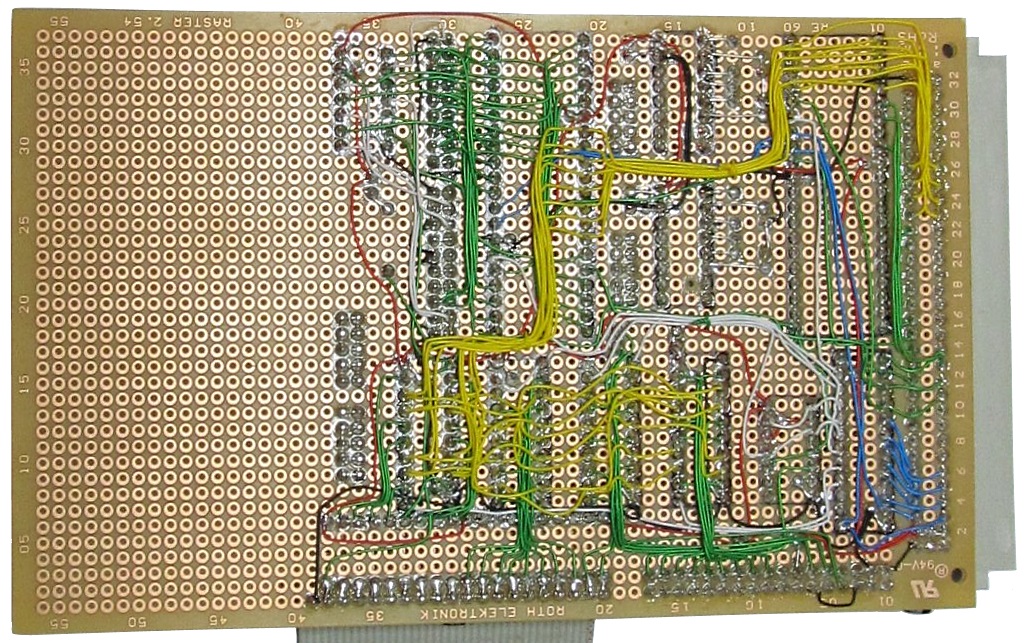
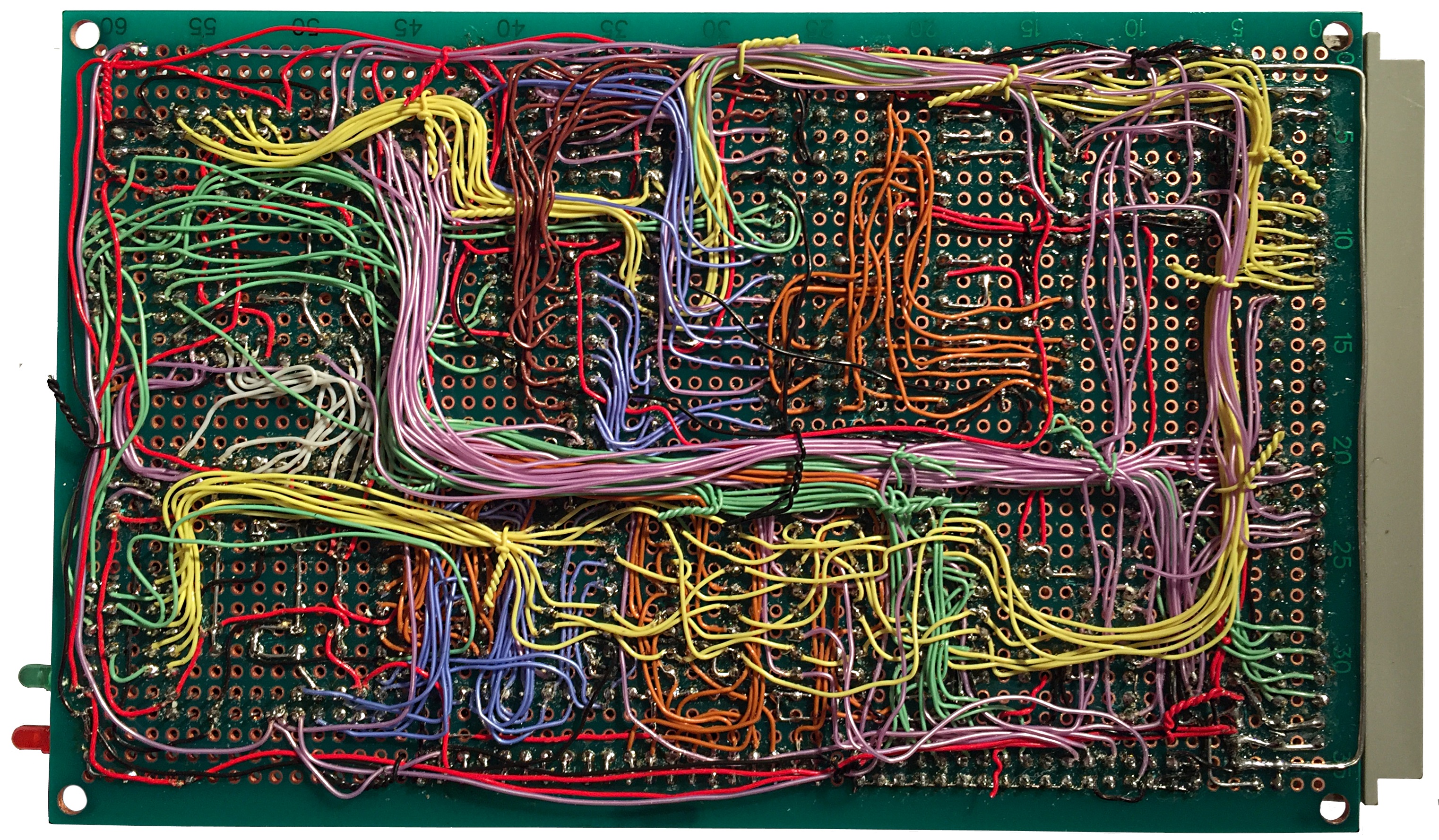
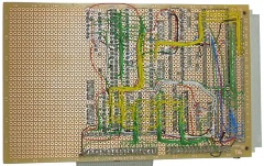
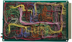
| The wiring side of the board, as you
can see, fully wired, there are a lot of connections - it
was definitely a better, if much slower, option to
fully wire the board at the outset, rather than
trying to do it piecemeal.
The only things not wired are the TTL RS232 port
and the PS/2 header will be added when I try out the
PS/2 to MTX keyboard logic. |
 |
|
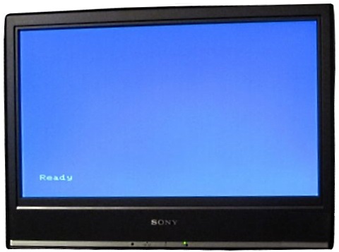
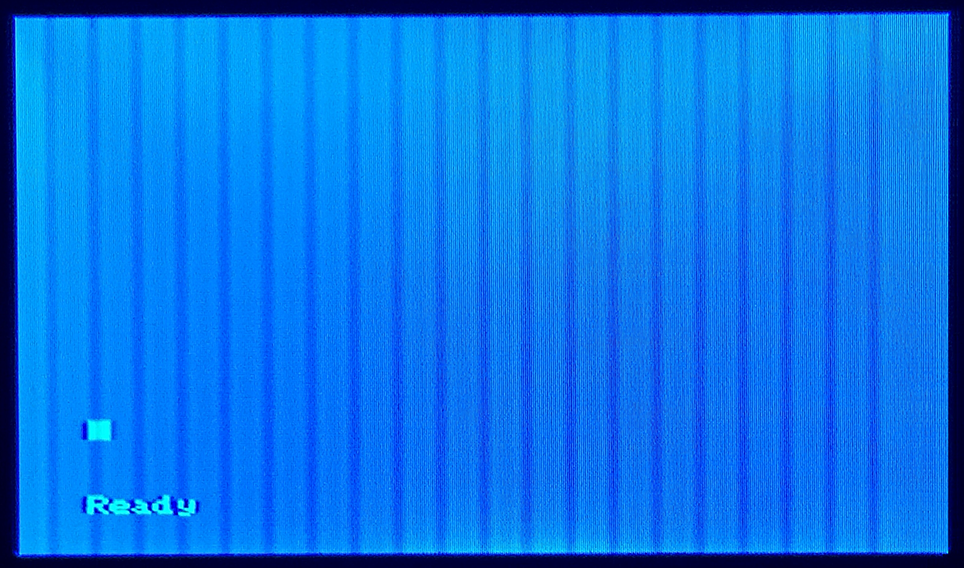
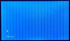
With the
MTXPlus+
"megaROM" programmed with the standard MTX ROM
images, the usual MTX BASIC "Ready"
prompt was displayed, even before the
I/O board
was connected.
At a
similar stage, Martin's system produced an "SE.B"
error message, likely due to the system reading
invalid data on the keyboard drive/sense lines. My
CPU board has pull-ups on the data bus that appear
to stop the bad data generating the BASIC error. |
 |
| The tests that I wanted
to do were with the proven MTX keyboard interface using the discrete logic
chips - a GAL22V10 (U21), a 74HC273 (U22) and 2 x
74HC244 (U23 & U24). When doing some final
checks before I plugged the I/O board in, I
discovered that I had made an error in connecting
the address lines to the GAL - I probably confused
myself when working on the underside of the board,
the address lines to the Z80SIO (U1), 82C55 (U4) and
the CPLD are correct though.
This wasn't too much of a problem - apart from
the fact that I don't have a copy of any GAL
programming software currently installed. Martin
kindly produced a new GAL program for me with my
"customisation" included. |
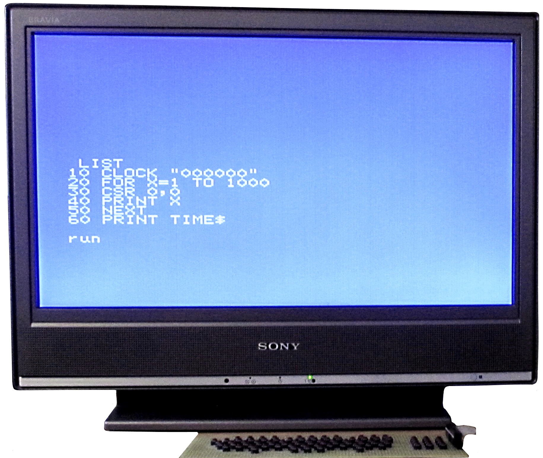
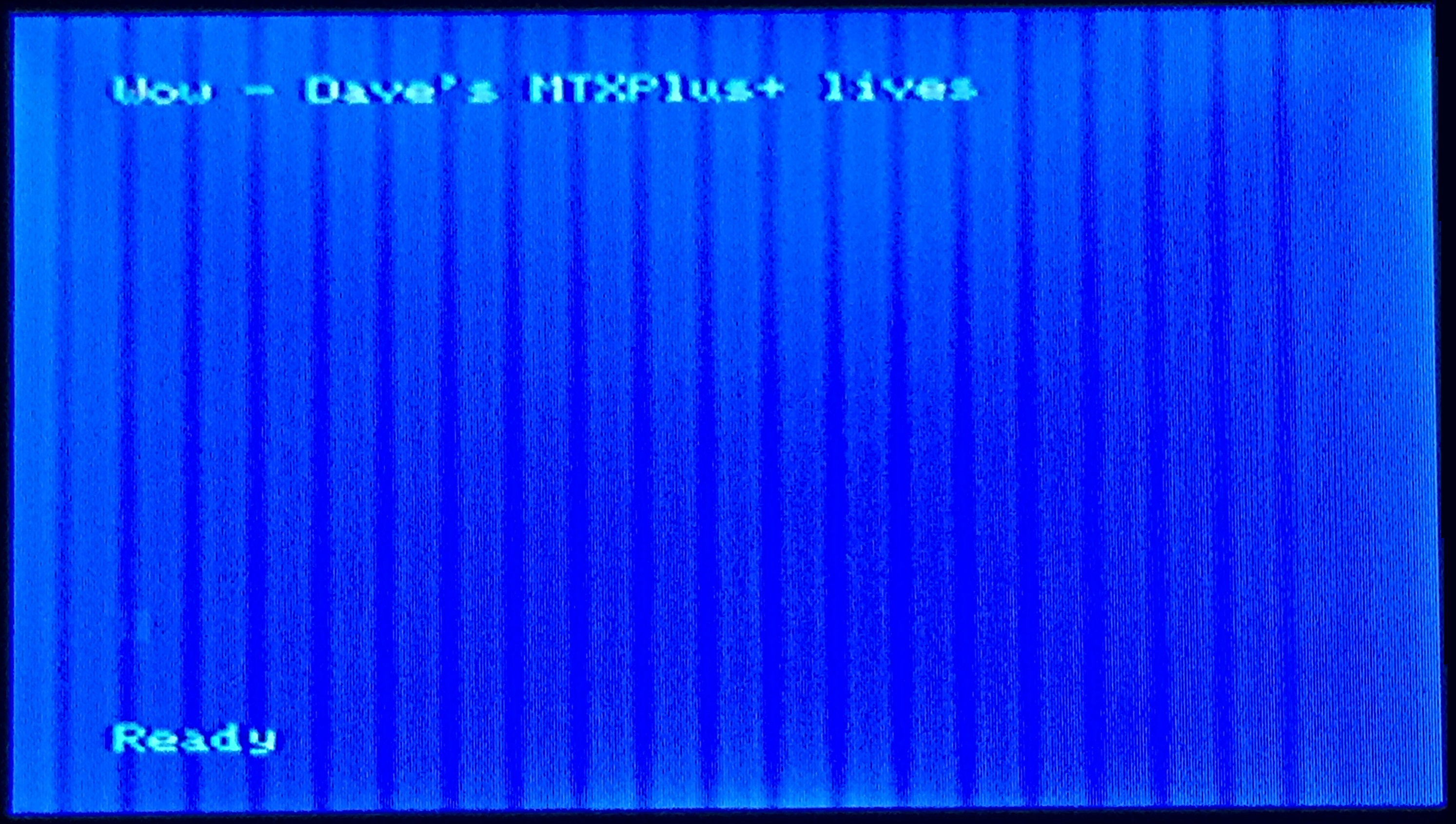
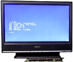
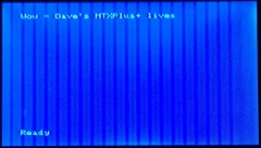
| With the modified GAL and keyboard
ICs installed, and an original MTX computer keyboard
connected, here you can see the first simple BASIC
program running on my MTXPlus+ The system can
"see" all 512KB of RAM,
PRINT PEEK(64122) returns the expected
"15" for the number of 32KB RAM pages. |
 |
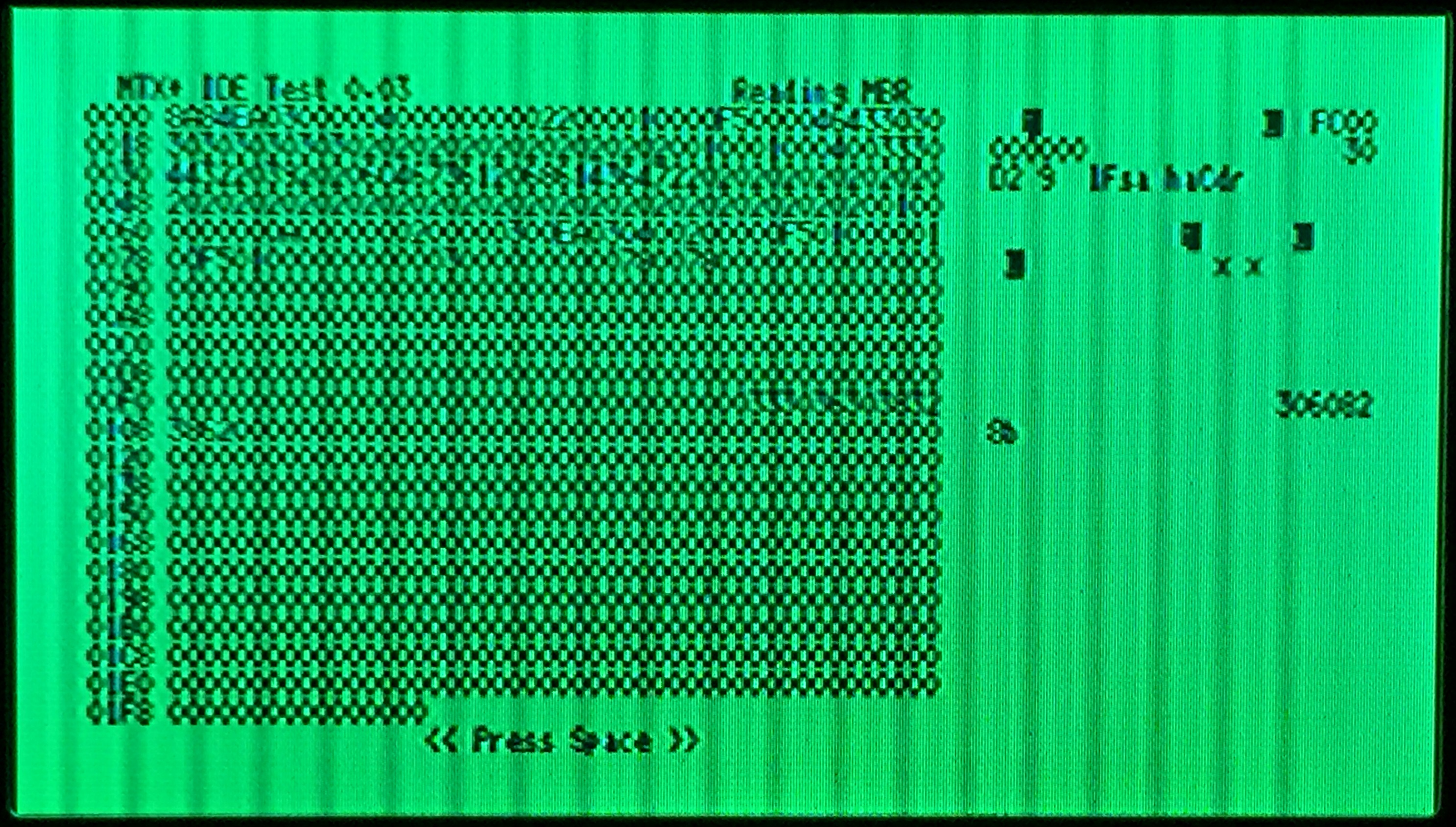
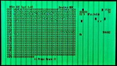
| To test the IDE/CF interface, the
82C55 PIA (U4), 74HC04 (U5) and the IDE power jumper
(JP3) were installed.
The ROM was programmed with Martin's IDE test ROM
and booting the system showed that the CF card could
be read, beginning with the Master Boot Record (MBR),
as shown. |
 |
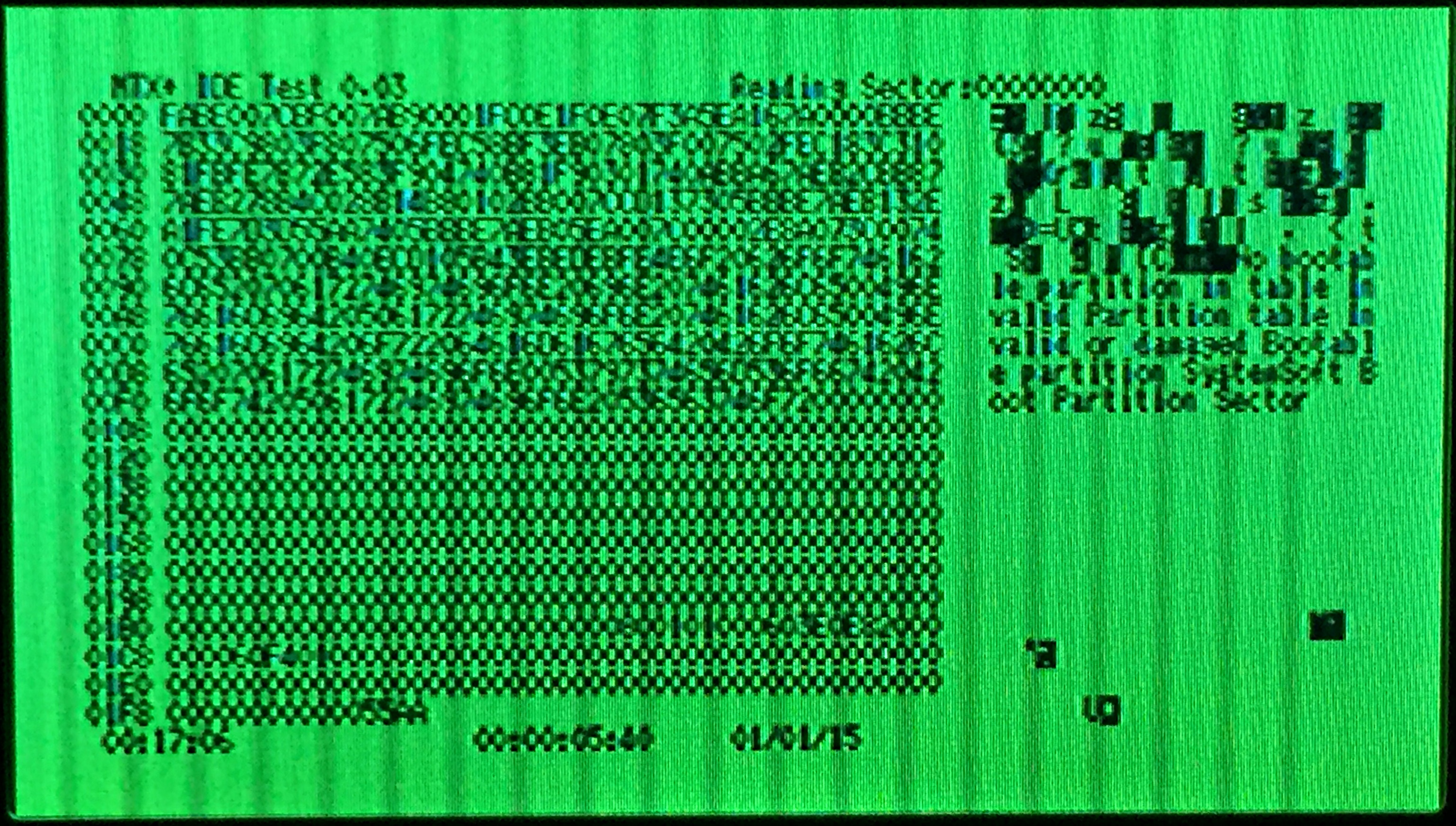
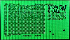
| Pressing the <space> bar causes the
program to step through the "disk" sectors and
display the contents as shown. |
 |
| And with the MTXPlus+ support ROM
installed, the system can quite happily use the CF
card. |
 |
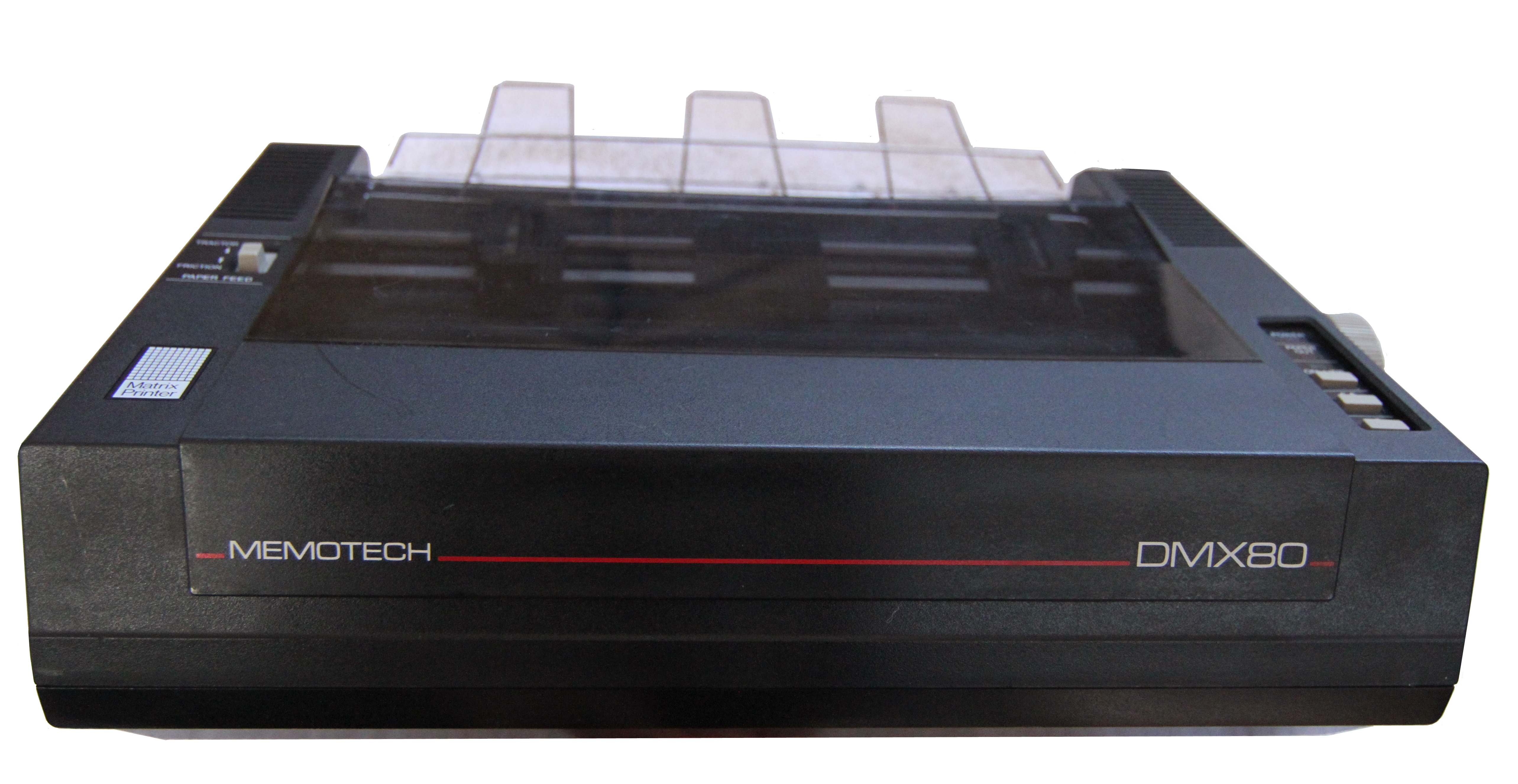
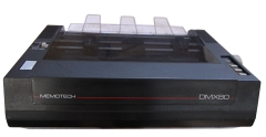
| After adding a 74HC374 (U25) and
74HC74 (U26), the printer interface was tested with
my Memotech DMX80 printer (previously
donated to me by Jan Seyfarth). The printer
interface worked with no problems, when I can think
of a more "interesting" photo of the printer in
action to post - I will. |
 |
| |
|
| |
|
|