|
"MTX Plus+" ROM
- Timing
 |
 |
|
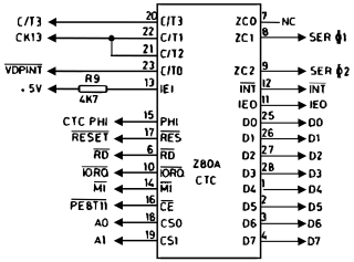
MTX CTC Pin-out |
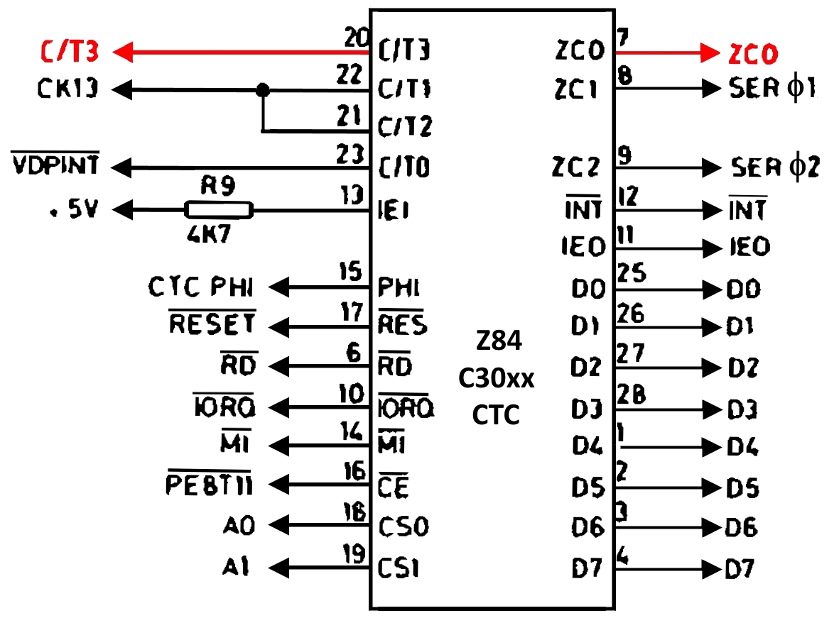
MTXPlus+ CTC Pin-out |
Background
Both the original MTX and MTXPlus+
computers include a Z80 Counter/Timer Circuit (CTC), the CTC has
four independently programmable counter/timer channels that can
be used to perform functions such as interrupt timing and clock
rate generation. Each channel has an external Clock/Timer
Trigger input (T/T0 to C/T3) and can drive one or two
outputs. Channels 0 to 2 each have an individual
Zero Count/Timeout output (ZC0 to ZC2) and all channels
can drive the Interrupt Request (INT)
pin.
The diagrams above show the connections to the Z80 CTC for
the original MTX and MTXPlus+, the only differences
being the connections to pins 20 and 7. Allocation of the CTC
channels for the MTX and MTXPlus+
are shown in the table below :
| CTC Pin-out |
MTX |
MTXPlus+ |
| External
Clock/Timer Trigger inputs, C/Tx |
|
|
0 |
|
23 |
VDP Interrupt |
VDP Interrupt |
| 1 |
22 |
CK4/13 (For DART Channel 1) |
CK4/13 (For SIO Channel 1) |
| 2 |
21 |
CK4/13 (For DART Channel 2) |
CK4/13 (For SIO Channel 2) |
| 3 |
20 |
Cassette Interface |
125 Hz
interrupt clock input |
|
Zero Count/Timeout outputs, ZCx |
|
|
0 |
|
7 |
Not used |
Raw VDPINT
Interrupt clock output |
| 1 |
8 |
Serial Clock for DART Channel 1 |
Serial Clock for SIO Channel 1 |
| 2 |
9 |
Serial Clock for DART Channel 2 |
Serial Clock for SIO Channel 2 |
As the device name suggests, each channel can be configured
as either a counter or a timer. Each channel is programmed with
two or three (if interrupts are enabled) 8 bit words - a control
word and a time-constant word.
| When in Timing mode, each channel has a
selectable pre-scaler (set in the control word) which
divides the system clock by either 16 or 256, and a
time-constant word that can have values from 1 to 256,
that can be used to specify the interrupt frequency. (Equation
1) |
|
Interrupt frequency |
= |
PHI |
| Prescaler * Time
Constant |
|
Time related functions in the MTX, such as the system clock and keyboard repeat rate, are controlled by
periodic interrupts with a frequency of 125Hz which are
generated by the CTC.
Channel 0 of the CTC is connected to the VDP interrupt
output pin (VDPINT), the VDP generates an interrupt signal at the end of each
active display scan, which, in the case of the TMS9929A, is
about every 1/50 second. The MTX ROM has an interrupt routine
called VDPINT that handles the internal clock, key auto repeat,
cursor flash and some sound functions.
| The interrupt is generated by CTC channel 0, but instead of using the
VDPINT signal as
a trigger, it uses the CTC timer mode to divide the CPU clock by
(256 * 125) to give a 125 Hz interrupt. |
|
Interrupt frequency |
= |
4
MHz |
| 256 * 125 |
|
| |
= |
125 Hz |
Using this method means that the interrupt period would be
the same for the NTSC (TMS9918, 60Hz) and PAL (TMS9929, 50Hz)
versions, allowing the ROM code to be common.1
MTXPlus+ Timing
If a copy of the MTX ROM, with interrupts
generated from the CPU clock, was used in MTXPlus+
without modification, then the time related functions would only
be correct when the system was operated at 4MHz, as the system
speed increased, so would the rate of the timing dependent
functions.
| When discussing how we were
going to handle the time related functions in MTXPlus+,
initial thoughts were around using CTC constants
appropriate for the clock frequency, at 16MHz though,
constraints in the CTC were somewhat problematic.
Using the maximum pre-scaler (256) value : |
|
Scaled frequency |
= |
16
MHz |
| 256 (pre-scaler) |
|
| |
= |
62500 |
| Using the maximum time
constant value (256), the minimum interrupt frequency
would be almost twice that expected - doubling the clock
tick rate etc. |
|
Interrupt frequency |
= |
62500 |
| 256 (counter
maximum) |
|
| |
= |
~244Hz |
Although it is possible to cascade more than one
counter to get values greater than 256, the problem would still
be that the interrupt frequency would only be correct for a
single clock speed. To keep the timing correct at all clock
speeds without having to change constants in the software for
each, some method of automatically controlling the interrupt
frequency was required.
Tony Brewer suggested a mechanism for doing this
that didn't need additional resources (on my board anyway),
using the redundant CTC channels C/T3 and ZC0, as well as spare
I/O in the CPU control buffer GAL2,
enabling the GAL to count ZC0 pulses and generate 125Hz
interrupts for any of the three defined clock speeds.
| GAL
Inputs |
GAL Logic |
| CPU
Clock speed select |
MHz |
|
VDPINT frequency divide counters -
internal use only - no physical outputs |
|
/ZC0_CNT0
|
: = |
ZC0_CNT0 |
|
/ZC0_CNT1 |
: = |
/ZC0_CNT0
|
* |
/ZC0_CNT1 |
(00 -> 01) |
|
|
+ |
ZC0_CNT0
|
* |
ZC0_CNT1 |
(11 -> 00) |
* A "00" value on PS1/PS0 is a variable rate
slow clock used for testing |
| PS1 |
PS0 |
| 0 |
0 |
n/a* |
| 0 |
1 |
4 |
| 1 |
0 |
8 |
| 1 |
1 |
16 |
|
ZC0 |
CTC
Ch.2 Output |
|
CT/3 |
= |
/PS1 |
* |
PS0 |
* |
ZC0 |
|
|
| |
+ |
PS1 |
* |
/PS0 |
* |
ZC0_CNT0 |
|
|
| |
+ |
PS1 |
* |
PS0 |
* |
ZC0_CNT0 |
* |
ZC0_CNT1 |
| |
| |
4 MHz |
CT/3 |
= |
ZC0 |
| |
8 MHz |
CT/3 |
= |
ZC0 / 2 |
| |
16 MHz |
CT/3 |
= |
ZC0 / 4 |
|
| GAL
Outputs |
| ZC0_CNT0 |
(Internal use) |
| ZC0_CNT1 |
(Internal use) |
|
C_T3 |
CTC Ch.3 Input |
| (125Hz clock for
interrupt) |
The CTC is programmed to output the
interrupt signal derived from the MTX ROM, i.e., the CPU
clock divided by (256 * 125), resulting in ZC0 frequencies
of 500, 250 or 125 Hz for CPU clocks speeds of 16, 8 and 4
MHz respectively. Based on the configuration of the CPU
clock speed select switches, the GAL divides the ZC0
frequency by 4, 2 or 1 and feeds back into the CTC C/T3
input at 125Hz, independent of CPU clock speed.
Design Development
Having the GAL22V10 divide ZC0 by 1, 2, 3 or 4 for 4, 8, 12
or 16 MHz CPU clocks was an ideal solution when the system clock
speeds were multiples of 4MHz, but becomes less useful now that
the system has the capability of running at clock rates that are
not multiples of 4MHz.
The
GAL22V10 has now ben removed and the CTC ZC0
output fed back directly to the CTC C/T3 input.
ZC0 pulses high whenever CTC channel 0 down-counter reaches
zero. This will happen in two different cases, when :
(a) CPU clock is divided to generate 125
Hz interrupt or
(b) /VDPINT input used to generate
interrupt, as discussed separately below.
For a normal MTX at 4 MHz, the CPU clock is divided by a pre-scaler
of 256 and a time constant of 125 to generate the 125 Hz
interrupt (see Equation 1 above). The
time constant value is pure coincidence as 4000000 / (256*125) =
125. A time constant of 250 for an 8 MHz clock and maximum of
256 (0 value is programmed) for 8.192 MHz clock is possible.
Anything higher ('fast') requires two cascaded CTC channels,
0 and 3, the latter, otherwise unused cassette interface, is not
supported.
If 'fast' = 10 MHz, have channel 0 pre-scaler of 16 (cannot
be 256), time constant of 125 and channel 3 time constant of 40.
If 'fast' = 12 MHz, have channel 0 pre-scaler of 16 (or 256),
time constant of 125 and channel 3 time constant of 48 (or 3).
Channel 0 is in timer mode and channel 3 in counter mode with
no pre-scaler available and external trigger ZC0. Therefore
simply connect ZC0 output to C/T3 input and remove C/T3 from all
other devices.
Time constant of 1 ensures that /INT goes low every time
/VDPINT goes low so that CPU is interrupted 50 times per second
at the end of active display. As ZC0 will go high whenever
/VDPINT and hence /INT go low, we have a choice of which of /INT
or ZC0 to connect to CPLD for Speculator logic (which must know
when /INT goes low) but we don't need both.
N.B. ZC0 and C/T3 changes mean must have different interrupt
code for 4MHz and 'fast'. If latter is only 8 MHz now as
temporary measure, only one byte would differ (time constant 125
or 250) as one CTC channel sufficient for 125 Hz (but not true
for 10+ MHz).
Explanation of currently implemented ROM code (from
Martin)
The current setup for the CTC is :
Channel 0 is set up as follows:
| The control word is now &25 which is a
bit pattern of 0010 0101 |
| Bit 7 clear |
– no interrupt |
| Bit 6 clear |
– timer mode |
| Bit 5 set |
– pre-scaler 256 |
| Bit 4 clear |
– falling edge detection |
| Bit 3 clear |
– automatic trigger when time constant is
loaded |
| Bit 2 set |
– time constant follows |
| Bit 1 clear |
– continued operation |
| Bit 0 set |
– identifies control word |
The original MTX code would have had the interrupt bit
set, as this was the only counter in use The modified hardware
has the output to this pin connected to the input of channel 3
The timer constant that follows is 31 (decimal) instead of 125.
At 4mhz counting to 125, with a pre-scale of 256 results in an
interrupt every 32000 cycles, giving the system its 125hz
interrupt.
The MTXPlus+ however, with it’s count of 31 and a pre-scale of
31, results in the input of channel 3 being pulsed every 7936
cycles.
Channel 3 is set up as a counter and not a timer
| The control word is &D5 which is bit
pattern 1101 0101 |
| Bit 7 set |
– Trigger an interrupt |
| Bit 6 set |
– Counter mode |
| Bit 5 clear |
– not used in count mode |
| Bit 4 set |
– Rising edge detection
( NB I’m not quite sure
why I changed that in theory either edge should work) |
| Bit 3 clear |
– not used in count mode |
| Bit 2 set |
– time constant follows |
| Bit 1 clear |
– continued operation |
| Bit 0 set |
– identifies control word |
The time constant that follows is the CPU speed in MHZ
that’s detected on start up.
So, channel 0 triggers channel 3 every 7936 cycles, If the
MTXplus+ CPU is running at 4mhz, that results in the channel 3
interrupt being triggered every 31744 cycles, Which is a
fraction faster than the original MTX, there are now an average
126.008 interrupts per second. So by changing the count for the
software clock from 125 to 126, TIME$ is now sufficiently
accurate for normal use.
Using the CPU speed as the constant for the 2nd stage
count means that whatever speed the CPU is clocked at, as long
as its an exact number of MHz, the result is a 126hz tick i.e.
10MHz CPU, the interrupt triggers every 79360 cycles, 10,000,000
/ 79360 = 126.008 as above, the system clock runs as before.
At 10.5mhz, the interrupt would still trigger every 79360
cycles, however 10,500,00 / 79360 = 132.3 so the system clock
will run 5% fast
"Final" Implementation
Using CPLD or GAL logic developed by Tony, MTXPlus+
now has the ability to operate at any one of 16 clock
frequencies from 4MHz to 16MHz. To support this, 16 different
CTC time constants are required :
| Clock |
/? |
MHz |
125 Hz Error |
CTC Time Constants |
| 0 |
8 |
4.00 |
|
16,125 |
(4,000,000) |
| 1 |
7 |
4.57 |
1s in 8001s |
18,127 |
(4,572,000) |
| 2 |
6½ |
4.92 |
1s in 4570s |
23,107 |
(4,922,000) |
| 3 |
6 |
5.33 |
1s in 8001s |
21,127 |
(5,334,000) |
| 4 |
5½ |
5.82 |
1s in 3201s |
15,194 |
(5,820,000) |
| 5 |
5 |
6.40 |
|
25,128 |
(6,400,000) |
| 6 |
4½ |
7.11 |
1s in 8001s |
28,127 |
(7,112,000) |
| 7 |
4 |
8.00 |
|
32,125 |
(8,000,000) |
| 8 |
3¾ |
8.53 |
1s in 12801s |
17,251 |
(8,534,000) |
| 9 |
3½ |
9.14 |
1s in 8001s |
36,127 |
(9,144,000) |
| 10 |
3¼ |
9.85 |
1s in 4570s |
46,107 |
(9,844,000) |
| 11 |
3 |
10.67 |
1s in 8001s |
42,127 |
(10,668,000) |
| 12 |
2¾ |
11.64 |
1s in 7112s |
23,253 |
(11,638,000) |
| 13 |
2½ |
12.80 |
|
50,128 |
(12,800,000) |
| 14 |
2¼ |
14.22 |
1s in 80011s |
56,127 |
(14,224,000) |
| 15 |
2 |
16.00 |
|
64,125 |
(16,000,000) |
For clock frequencies of 4, 6.40, 8.0, 12.80 and
16.0MHz, the clocks can generate a 125 Hz interrupt precisely,
the rest have small errors as listed in the table of CTC time
constants, the worst case error is at 5.82MHz, where the error
is 1s in 3201, i.e., 1s in 53 minutes, or approximately 26
seconds per day.
Identifying the CPU speed, in software
The MTXPlus+ is designed to have an adjustable CPU clock.
4MHz for Compatibility with the MTX, mostly for games, and a
range of faster speeds to take advantage of the enhanced
hardware.
The support ROM, therefore uses the on-board RTC chip to
calculate the CPU speed. To do this it counts how many
processor cycles it completes in one second of real time as
determined by the DS12887. The ROM counts how many times it
executes a 9874 cycle sub routine, It’s a slightly odd figure as
the count routine averages 126 cycles per loop which has to be
taken into account. From there it knows to within 0.01 of a MHz
how fast the system clock is. Tested with an 11.0592mhz
oscillator it reported 11.06, close enough!
The CTC only counts in integers, which for the majority of
available oscillators isn’t a problem, Having the 4MHz
compatibility mode really means the master clock is going to be
some multiple of that anyway.
Credits :
1
Information about the CTC configuration in the original MTX ROM
courtesy of Tony Brewer, January 2015
Notes
:
2 Utilising the GAL22V10 used on Dave's CPU
board to buffer the Z80 control signals
|