My original intent was to have a separate ROM board, having 8
ROM sockets to cater for each of the physical Memotech 8KB ROMs and switch
them in as required using the MTX Page Port in much the same way
as in the original MTX. However, this proved to be unnecessary
as Lez's parts kit included
a much larger
EEROM, the 128KB (128k x 8) Winbond W27C010.
The “Colour CPM ROM” was initially developed in an attempt to allow the CPU to run
faster than 11MHz. It uses additional software delays on all
accesses to the VDP in order to prevent the OS from losing data
being transmitted to the VDP. Compatibility with previously
written MTX games etc. is “poor”. However in BASIC and CPM it’s
been possible to achieve 20Mhz on Martin's short backplane
prototype.
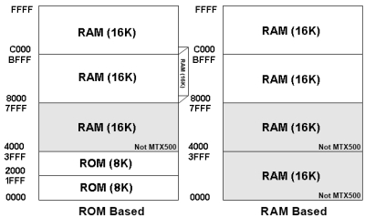
To understand
the ROM configuration for MTXPlus+, it is probably helpful to
review the memory map for MTXPlus+
and see how it relates to the original MTX.
| MTXPlus+ Memory Overview |
|
|
MTXPlus+ ROM Configuration
Each half of the 128KB
ROM on the CPU board contains copies of the Memotech OS, BASIC, ASSEM,
CP/M and SDX ROMs, as well as the support ROM for MTXPlus+.
| MTXPlus ROM Map |
|
Address |
Image |
A15 |
A14 |
A13 |
| 0000-1FFF |
OS |
0 |
0 |
0 |
| 2000-3FFF |
ASSEM |
(ROM 1) |
0 |
0 |
1 |
| 4000-5FFF |
BASIC |
(ROM 0) |
0 |
1 |
0 |
| 6000-7FFF |
(not used) |
(ROM 2) |
0 |
1 |
1 |
| 8000-9FFF |
(empty) |
(ROM 3) |
1 |
0 |
0 |
| A000-BFFF |
FDX |
(ROM 4) |
1 |
0 |
1 |
| C000-DFFF |
SDX |
(ROM 5) |
1 |
1 |
0 |
| E000-FFFF |
MTX+ support |
1 |
1 |
1 |
The OS and BASIC ROMs are
assembled as a single 16k unit just like the MTX-04
board. |
|
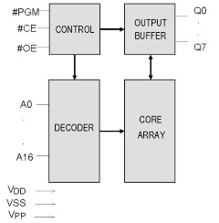
Winbond W27C010
block diagram |
|
 |
|
MTXPlus+ OS ROM Customisation
Given my very limited Z80 programming
ability, the "base case" for MTXPlus+ was that
the system would be useable by just dropping in a set of
unmodified MTX ROMs and having the system operate
identically to an MTX512. The obvious benefit of this is the
ability to have a working system without having to write an
operating system from scratch, the downside being that there
would be no access to any MTXPlus+ enhancements
such as faster CPU speed, enhanced graphics, Compact Flash
storage, Real Time Clock, etc.
A new operating system could, and should, be
written to take full advantage of these features, but this
is not a trivial exercise, so, the design caters for an
intermediate position where MTXPlus+ enhancements
can be enabled by modifying the original MTX ROMs. Even this
task would have been a challenge for me, but, thankfully,
Martin has done all the work!
The original Memotech ROMs were packed with
features, packed to such an extent that there is very
little, if any, space available for additional code.
Although some functions such as tape load and save could be
removed, there would still be insufficient space for all of
the MTXPlus+ enhancements, this is where the
"Support" ROM comes in. If there is insufficient space in
the base ROMs to enable MTXPlus+ features,
additional code can be installed in the Support ROM and
called from the base ROMs.
The majority of enhancements in MTXPlus+
comprise upgraded hardware along with corresponding
modifications in the system ROMs. The main areas where ROM
modifications have been implemented are :-
Some enhancements are supported by the
hardware and do not require changes to the existing ROMs :-
Additional details of the specific functions
can be found by following the links above.
Since the MTXPlus+ ROM does not need to include the tape
routines from the original ROM, Martin has eked out some
space to make the original MTX "terse" (i.e., atrocious)
error messages rather more informative.
This table compares
the MTXPlus+ error messages with those from the original
ROM.
MTXPlus+ OS ROM
Technical Details - Courtesy of Martin
There are sufficient difference between the two 64k ROM
images that make up the 128k flash, that they are assembled
from separate files. The 2 binary output files are then
combined for writing to the flash chip.
Though the ROM contents differ, they’re both laid out the
same way: the first 8k of the flash is the OS ROM that
resides in the first 8k of memory when the ROMS are paged in
(RELCPMH=0) The remaining 7, 8k images, are paged ROMs,
each assembled to live in the remaining ROM space from
8-16k, and selected by bits R0-2 of the page port just like
the original MTX. For ease of assembly, since the OS and
Assem ROMs are logically a single unit and assembled that
way, the order of the pages ROMs is:
| |
Range |
Content |
| ROM 1 |
8-16k |
ASSEM |
| ROM 0 |
16-24k |
BASIC |
| ROM 2 |
24-32k |
|
| ROM 3 |
32-40k |
|
| ROM 4 |
40-48k |
CPM Boot ROM |
| ROM 5 |
48-56k |
SDX Disc ROM |
| ROM 6 |
56-64k |
MTXPlus+ Support ROM |
The current page mapping deliberately
makes ROM 2 inaccessible, as that was used by Memotech for
ROM based software. This allows for the possibility of
modified versions of the Pascal and/or Newword ROMs to run.
The “Mono CPM ROM” relies on the V9958’s
hardware wait system to ensure data transfer between the CPU
and VDP are kept in sync. This Basically limits the Z80 to
running at or below the speed of the VDP. Running this ROM
with a clock speed of over 11MHz can result in video
corruption as data from the CPU can be lost in transit to
the VDP. However at slower speeds, this system is more
compatible with the original MTX, as it prevents video data
loss from software that was written to meet the timing
requirements of the original 4MHz CPU.
Modifications to
the original MTX ROMs
The OS, ASSEM,
and BASIC ROMs are mostly the same as the original, with the
following changes:
|
Mono ROM Block |
|
OS ROM |
|
Memory Address (hex) |
Modification |
|
0006-0007 |
The original jump to 0194h
now goes to the V9958 setup code, which jumps to
0194h on completion |
| 091C
|
CTC interrupt count
increased from 124 +”0” to 125+”0” |
| 099C –
09AF |
CTC setup changes for the 2
stage counter.
The first stage counter is now
set to count 126 ticks per mhz, the extra stage uses
the calculated clock frequency to trip the interrupt
126 times a sec, but that assumes there’s no
fractional frequency. |
|
0A53-0CAA |
Tape loading code removed
and re-used for support routines.
The inout
routine is replaced with a dummy routine that just
updates the pointers and reports success, but does
no loading.
The load and save entry points are
maintained but report “undefined”
The V9958 and
remainder of the extra CTC setup code resides here,
as does the RTC to CLOCK and CLOCK to RTC code
Total differences, around 600 bytes. |
| |
|
ASSEM ROM (ROM 1) |
|
Memory Address (hex) |
Modification |
| |
No changes |
| |
|
BASIC ROM (ROM 0) |
|
Memory Address (hex) |
Modification |
32D9h
[Offset 52D9 in the ROM] |
The “adjval” routine in the
tape area has moved, this is an external reference
to part of that routine, so the address has changed
slightly. |
| |
|
|
ROM 2 |
The ROM
2 slot is empty by design |
| |
|
|
ROM 3 |
ROM 3
is not used and is also empty |
| |
|
|
ROM 4 |
Mono CPM
This is an adaptation of the original FDX code with
low level changes to drive the CF. The display uses
the V9958 in text 2 mode, which is why the display
is in mono, scrolling is done in software, and the
cursor is programmed using the built in character
flash abilities of text 2. |
| |
|
|
ROM 5 |
This is a near standard SDX
image, the low level disc driver is the same as the
one in ROM 4.
It's a "work in progress", as
there are some additional commands from the CFX/SFX
code branch to be added back in once they’re
complete. |
| |
|
|
ROM 6 |
The support MTXPlus+ ROM.
Originally this ROM was to have all the FAT32
code. Currently it contains the boot screen, start
up tones and CPU clock detect software and not a
whole lot else |
|
Colour ROM Block |
OS, ASSEM and BASIC ROMs - include the same
modifications as the Mono ROM
In
addition the are numerous “patches” through the 3
ROMs in order to intercept all transfers to and from
the VDP. The Z80 opcodes IN A,(port) and OUT
(port),A which handle all VDP transfers are 2 bytes
long, the jump instruction needed to access the
patch code needs 3 bytes. This means moving at least
one additional instruction to make room, leading to
a multitude of slightly different patches.
The patch code within the former tape code area then
calls a replacement IN or OUT routine which has a
software delay before returning
That makes
an extra 100 or so bytes changed spread all over the
3 roms. |
| |
|
|
ROM 2 |
The ROM
2 slot is empty by design |
| |
|
|
ROM 3 |
This is
the Data ROM for the Colour CP/M text display
driver, Colour map lookup table, 3/4k. Ink/Paper
lookup table, 1/2k, 2 character sets 2k each, plus
Palette data and a non booting header. |
| |
|
|
ROM 4 |
Colour CPM
Further adapted from the FDX ROM, the display is now
the bitmapped 16 colour Graphics 6 mode (512x192).
Scrolling is done using the VDP’s block move
command, as moving up to 48k in software is quite
time consuming. The cursor is generated using one of
the sprites available in graphic modes.
To match
the the 80 column board’s colour scheme, the palette
registers are reprogrammed to produce an RGBI style
8 colours + bright. Even with the hardware assist,
and faster CPU availability, text handling in CP/M
is somewhat slower than the mono version. |
| |
|
|
ROM 5 |
SDX basic extensions, runs
the same code as the Mono ROM. |
| |
|
|
ROM 6 |
The support MTXPlus+ ROM.
The support ROM is mostly the same as the Mono
version, with the major change being the software
delays added to the screen handling. |
The builder program currently puts the
“colour CP/M” ROM and the associated ROMs into the first 64k
of the flash and the “Mono CPM” ROM and its ROMs into the
upper 64k.
The initial design of the CPU board included
a jumper block which connected the ROM's A16 address line to
either 0V or 5V to select either the colour or mono ROM
sets. The CPLD version of the CPU board now uses a
DIP-switch input to the CPLD and additional logic to set the
ROM A16 address line and select the appropriate ROM block.