|
 |
The Memotech MTX Series |
 |
Memotech MTX
- Various Failures
System Description : MTX500 Serial
No.(missing), 4000-04 computer board with 32k DRAM chips.
Problem Description : System dead, black
screen with no sound at power on
Resolution Summary : Replaced failed 74S04,
74LS374 and upgraded on board RAM to 64k
Darren sent me two faulty MTX computers, his original
"MTX500" (which has a MTX512 keyboard) and an MTX512 that he had
obtained later, and made the attractive offer that, if I fixed
his original machine, then I could keep the other one for the
collection.
Darren reported that the "512 boots to a ready prompt, but
the keyboard doesn't work, the 500 simply shows a black screen."
When they got to me, neither of the machines booted and both
displayed a black screen on power on. Although Darren wasn't in
any hurry to get his "MTX500" back, (he was about to move
house), I decided to start with the "MTX500" to get that repair
out of the way then I could work on the "MTX512" as my time
allows (or doesn't!).
Initial inspection of the computer board revealed that
someone had previously worked on the machine; as well as a
number of passive components having been replaced, the 16k ROM
had been removed from its socket and accidentally reinserted
with pin 16 (D4) not engaged in the socket! Had there been no
other faults, this would obviously have stopped the system from
working, but inserting the chip correctly made no difference to
the fault.
Darren didn't send me his power supplies, so I used one of my
known good ones for the testing. The first checks were to put a
DVM on the DC voltages - the VRAMs are a convenient point to
measure all of the DC voltages; Pin 1 should be -5VDC, Pin 16
should be 0V, Pin 9 should be +5VDC and Pin 8 should be +12VDC.
Worryingly, although the other voltages looked OK, the
voltage on Pin 1 was -6.0 VDC which I thought might have damaged
the VRAMs. With the video daughter board removed to get better
access to ZD3, the 5.1V zener diode that controls the -5VDC
line, I found some debris on the -5V side of the diode. I don't
know what the debris was and why it should have affected the
voltage, but cleaning it off returned the voltage to -5VDC.
However, it had no effect on the fault, but did leave me with
concerns about the integrity of the VRAMs.
As is common, the cable between the video daughter board and
the back panel connectors had broken, so my initial testing was
done using the TV output from the modulator. One of the most
frequent "fatal" fault symptoms on the MTX is a black screen
accompanied by a constant tone from the sound chip. Since I had
the black screen, but no audio tone, I wondered whether the RF
modulator was faulty, so I repaired the AV connections so that I
could check the sound and video outputs straight off the video
board. Again, this made no difference to the fault.
Since I have the luxury of having quite a few MTX spares, I
swapped out the majority of the socketed chips, i.e., the CPU,
CTC, VDP and ROMs with known good replacements, all to no
effect. When I was doing this, I noticed that someone had made
an odd modification in the region of the clock circuit on the
PCB - including adding a transistor where one was not originally
installed. The 74S04 (hex inverter) in board position 9D, used
in the clock circuit, was running VERY hot - an indication of
possible failure.
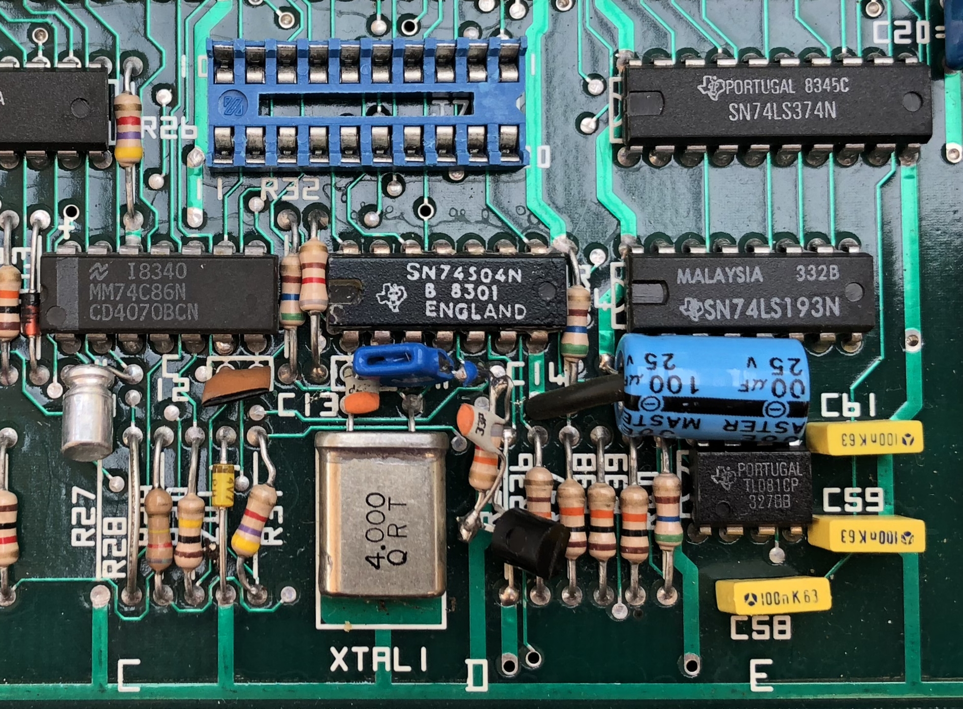
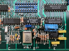
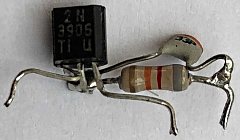
Close up of the clock
circuit modifications.
A resistor and
capacitor were connected to one side of the blue
47pF capacitor below the 74S04. What is not clear in
the photo is that that this leg had separated from
the capacitor body, i.e., the capacitor was open
circuit and likely the cause of the failed clock
signal. |
 |
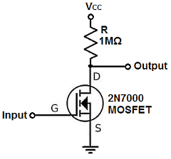
As described in
this link on the
Learning about electronics website, and
illustrated here, it is possible to make an inverter
out of a transistor, so I theorised that, rather
than replace the failed IC, someone had used a
transistor to replace a faulty gate in the 74S04.
Putting a 'scope of the clock line to the CPU
revealed that the expected 4MHz clock was absent so
I decided to replace the failed chip and remove the
transistor "bodge" to return the system to its
factory state. |
 |
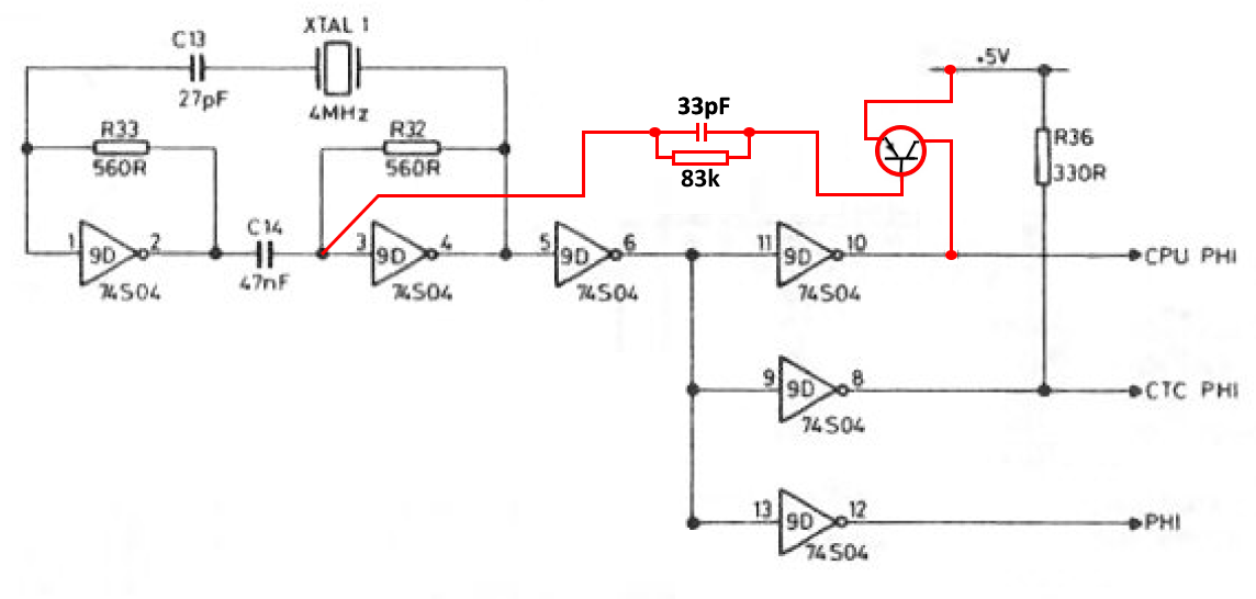
The clock modification
components, consisting of a 2N3905 PNP transistor,
resistor and capacitor.
When installed, they
were connected as shown below. |
 |
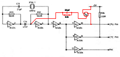
| The modified clock circuit,
the changes from the Memotech design are shown in
red. (R35, a 330R resistor, is normally installed
adjacent to R36. It had been removed and the
transistor installed as shown.) A 100uF electrolytic
capacitor has also been installed between 5V and 0V
adjacent to the 74S04 but I just left this in place. |
 |
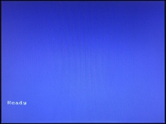
Ta-da ! - With the 74S04
replaced with a socket, a new chip installed, R35
replaced and the surplus components removed, the
machine now booted to the "Ready" prompt - the
composite video output is shown here.
You can
also see that my previous concerns about potential
damage to the VRAMs from the out of spec -5VDC line
were unfounded - the video output is fine. |
 |
However,
some problems remained, there was a constant tone
from the sound chip and the TV output was unusable -
although the "Ready" prompt was present, it was not
possible to get a decent picture from the RF output.
Having spoken to Darren, we decided that there
was no point in spending any time trying to improve
the modulator output, Darren, like most people these
days, would be using the composite video output and
had no need for a working RF output. So, the next
issue to be looked at was the audio output.
|
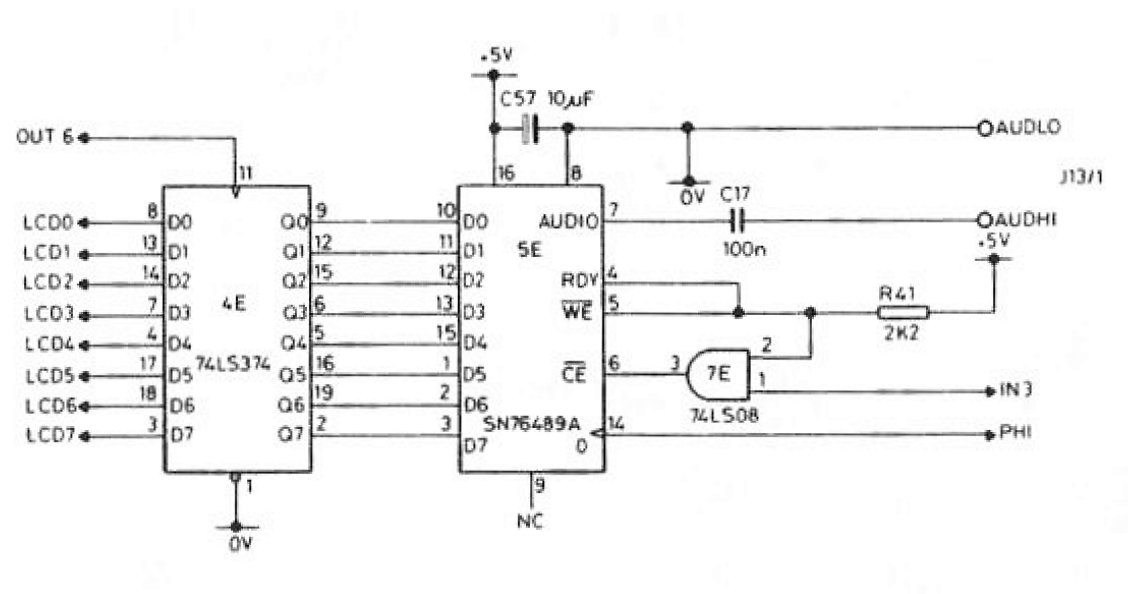
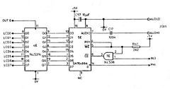
The MTX generates sound
using a
TI SN76489A complex sound generator (CSG) and
the SN74LS374N octal flip-flop that buffers the data
to it.
The relevant portion of the circuit
diagram from the MTX manual is shown opposite. |
 |
The system was generating a
constant tone with no sound commands active, but,
did respond to a <CTRL><G> ("Bell") command,
although the result was a strange siren type sound,
rather then the expected "ding", so the CSG was
working, at least, to some extent. Although I should
have followed a more structured fault finding
approach, I started by swapping out the CSG - as I
should probably have expected, this didn't make any
difference.
At that point, I got the 'scope
out and probed the sound port control lines, OUT(6)
and IN(3). Both of these appeared to be working as
expected so I compared the flip-flop outputs in
response to a <CTRL><G> with the outputs of a
working MTX. On the working MTX, all of the outputs
were seen to change state, but on this machine, bit
D7 (pin 2 of the '374) was stuck low.
As I
did not have a 74LS374N to hand, I replaced it with
a fully compatible SN74HCT374N and the sound problem
was resolved.
Note : since
this article was written, at least two other MTX
computers have been reported as having a constant
tone from the sound chip. In both cases, replacement
of the SN74LS374 has resolved the issue.
|
Although he had sent me an MTX500
and an MTX512, as it was his original machine,
Darren wanted me to return the MTX500 to him, rather
than the MTX512. When he mentioned that he was
probably going to look into making a 32k expansion
board, I offered to upgrade the onboard RAM to 64k
instead.
This process is not without risk,
when I first tried this a few years ago, I
managed to brick the MTX and ended up using one of
Andy's memory boards to get the system working.
I did eventually manage to recover the MTX and got
the RAM upgrade working. These days, my toolkit (and
my ability to use it) has improved and, having done
quite a number of PCB repairs since, I am relatively
confident of doing these upgrades without issue. In
the unlikely event that it does go horribly wrong,
then a separate memory card would be the fall-back.
|
As I had done this upgrade
before, I didn't take step-by-step photos, but you
can see the steps involved
here.
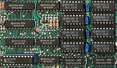
This photo shows the new RAMs
installed in sockets and the PAL replaced with a
suitably programmed GAL16V8A using the JED file from
Andy's hardware page. |
 |
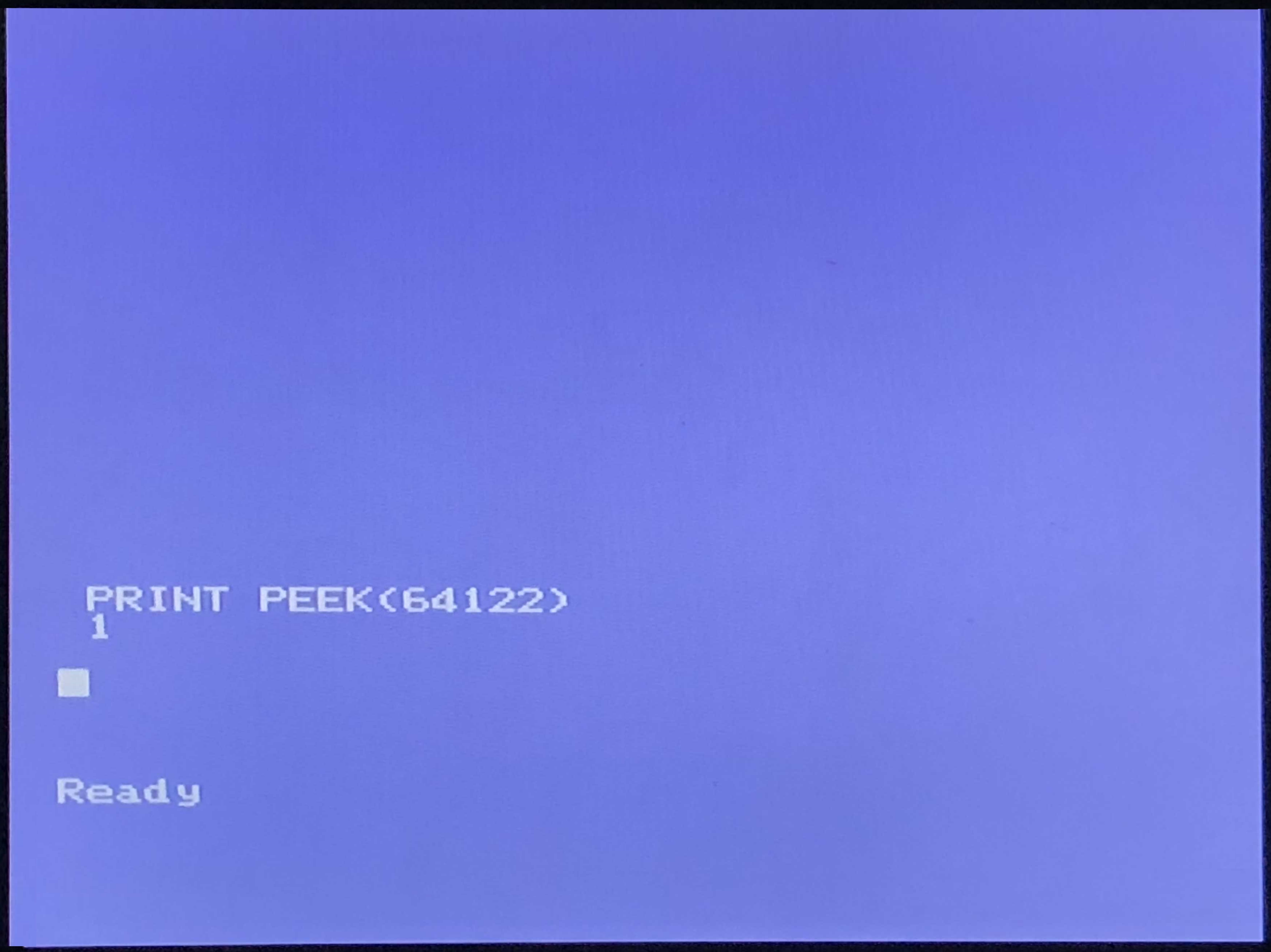
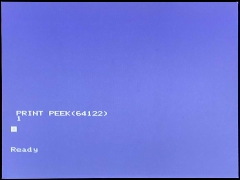
| Proving that the RAM
upgrade has worked and the full compliment of RAM is
visible to MTX BASIC, PRINT PEEK(64122) returns 1,
signifying 2, 32k pages of RAM are installed. |
 |
That completed the repairs and
upgrade to the computer board, all that remained to
be fixed was the keyboard.
The keyboard on
all but one of my MTXs has a pin header soldered
onto the keyboard PCB which connects to the computer
board with a 20 way ribbon cable. My other MTX, and
this one from Darren, had the ribbon cable soldered
directly onto the keyboard PCB. On this machine, the
ribbon cable had been torn from the keyboard PCB,
rendering it useless.
I removed the remnants
of the ribbon cable cores from the keyboard PCB and
used a Dremmel with a 1mm diameter drill to enlarge
the holes so that a SIL header could be fitted.
When repairing the broken cable, I saw that the
keyboard itself was in pretty poor shape. There was
a large amount of corrosion on the metal plate that
supports the keyboard PCB, possibly due to some
corrosive liquid (coffee?) being spilled on it.
It didn't come as a surprise to find that, when
the keyboard was plugged in, it had more than a few
problems! When new, the MTX keyboard worked really
well, but, when not used for extended periods, even
well preserved keyboards can be problematic. The
key-switches can become stiff and/or suffer from
varying degrees of "bounce". The majority of
key-switch issues can be resolved by thoroughly
exercising the affected keys, i.e., giving them a
good workout, will usually restore the keys to an
acceptable level of operation. If that fails, then
the key-switches can be replaced as described on
this page.
With the keyboard connected, I
found that one key-switch ("M") didn't work at all
and quite a number had unacceptable bounce - even
after vigorously exercising them. This meant that I
had quite a few switches to replace. |
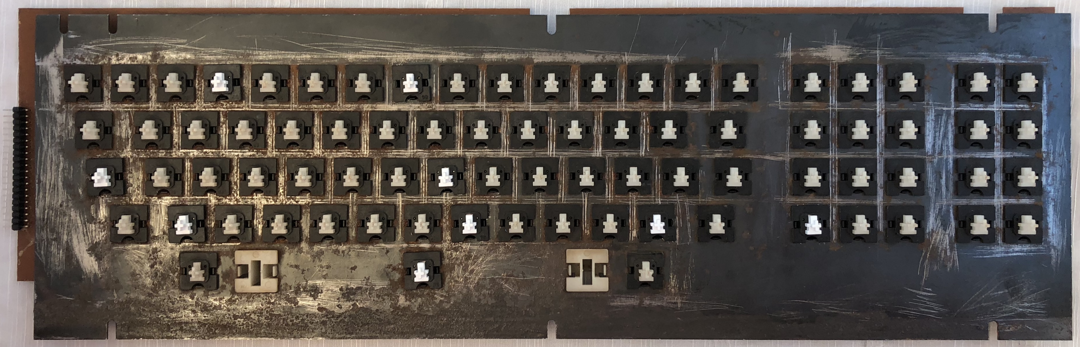
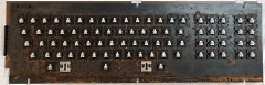
With the keycaps removed,
you can see how badly corroded the metal plate was.
(The shiny new cable header can be seen at the
left side) |
 |
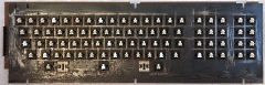
| Mounting plate cleaned up
and various key-switches replaced |
 |
| |
|
That completes the restoration of
Darren's original MTX500 so he can relive the joys
of MTX computing once he moves into his new house.
Fault finding and repair of the MTX512 that
I am keeping was a much simpler affair but is the subject of
another article. |
| |
|
| Parts
List |
Although Darren offered to pay for
the parts, as I noted above, my "fee" for doing the
work was to retain the other non-working MTX.
For information, I have included a list of the parts
used and indicative cost.
|
| Item |
No |
Cost |
Total |
| 74S04 & socket |
1 |
£1.00 |
£1.00 |
| Replacement key-switches |
10 |
£1.25 |
£12.50 |
| Keyboard ribbon cable |
1 |
£2.00 |
£2.00 |
| SN76489 & socket |
1 |
£1.25 |
£1.25 |
| SN74HCT374 & socket |
1 |
£1.25 |
£1.25 |
| 4164 & socket |
8 |
£1.50 |
£12.00 |
| GAL16V8A & socket |
1 |
£2.00 |
£2.00 |
| My time |
Lots! |
£0.00 |
£0.00 |
|