|
 |
The Memotech MTX Series |
 |
MTX500 RAM Upgrade to 64k (MTX512)
I purchased a second "MTX512" from eBay, when the item arrived,
it turned out to only have 32k of RAM. When I compared the
internals of this machine to the MTX512 that I bought new,
I found that my original MTX512 has the same 32k of RAM fitted
to the main board, along with an expansion memory board
soldered to the edge connector of the main board. As I
understand it, some MTX512 machines had 64k of RAM fitted to the
main board. Obviously, others, like mine, had the additional RAM
installed on an expansion board.
Until recently, I believed that in order to upgrade my second
machine to 64k of RAM, I would need to find and install a RAM
expansion card as fitted to my original machine. Given, the age
and scarcity of these machines, the likelihood of that was
pretty remote.
However, in June 2012, I came across a "Memotech MTX500
Upgrade Kit" advertised on eBay. This kit consisted of 8x64kbit
RAM chips along with a replacement address decoder that were intended
to replace the corresponding chips on an MTX500. This page
describes my experiences in attempting to install this "upgrade
kit".
It should be noted that Memotech did not market component
level upgrade kits
for the MTX500, the basis for this upgrade is the reverse
engineering and
Memory
Investigation done by Andy Key and posted on his website,
together with an "MTX Upgrade Kit" purchased off eBay.
If you're in a hurry,
see below for the
final outcome. -
Updated 08/08/2014 - it now works!
18/06/2012 - Upgrade kit purchased
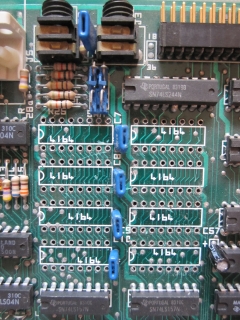
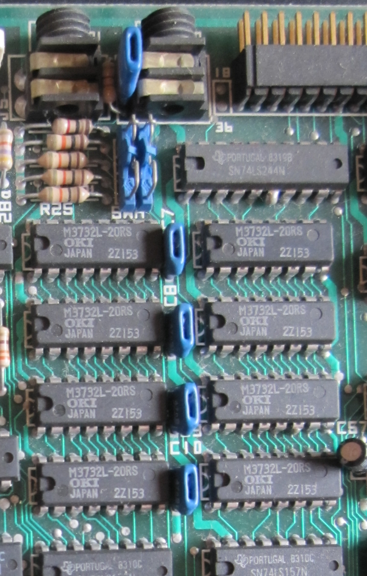
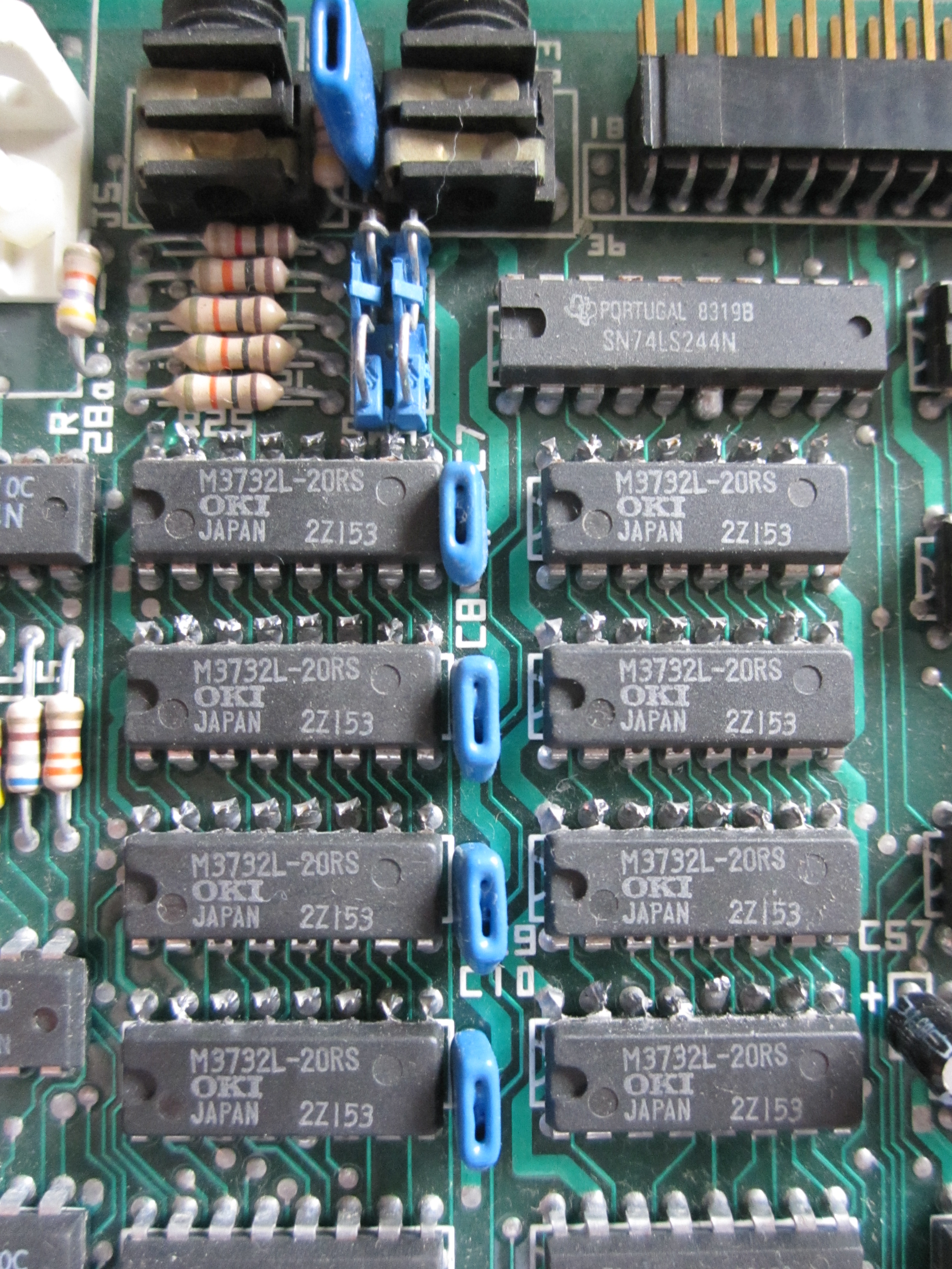
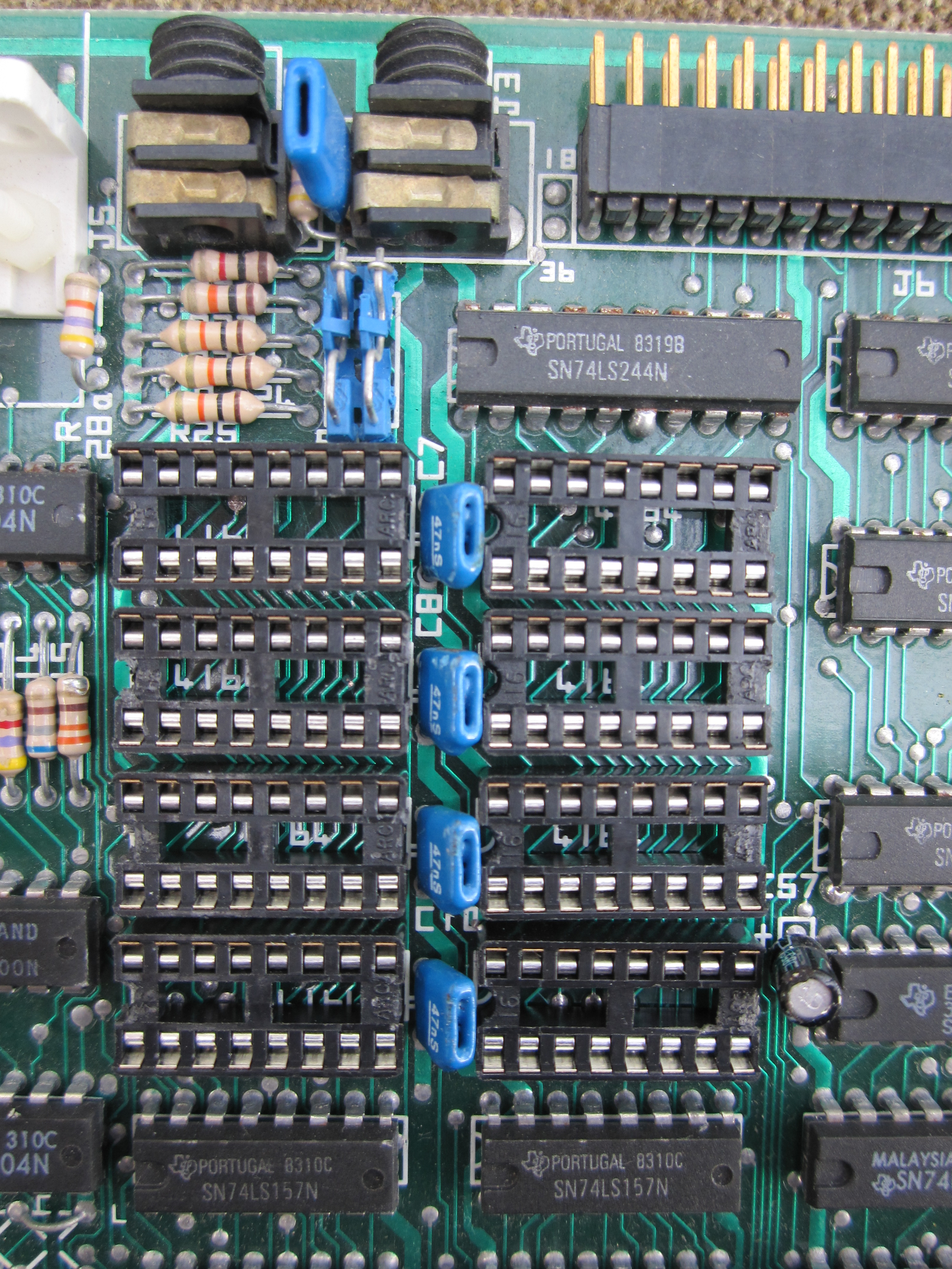
The upgrade kit consists of a set of DIL sockets and 64k RAM
chips to replace the 32k memory chips which are soldered
onto the motherboard at positions 2C to 5C and 2D to 5D. The
original chips were 8, 32kx1 bit RAM chips, some may have had
generic "4132" identifiers, but on both my machines, the chips
are M3732L-20RS from OKI semiconductor.
In addition to installing the extra RAM, the address decoder
chip on the motherboard must be upgraded to allow the system to
see the additional RAM. Address decoding for the original
machine was done by a
PAL, programmable logic device, a
Monolithic Memories PAL14L4
installed in position A6 on the main board. PALs are one-time
programmable, modification of the logic requires replacement of
the chip. This device is obsolete but can be replaced by an also
obsolete, but available,
Generic Array Logic device from
Lattice Semiconductor,
a GAL16V8. GALs are much more flexible
than PALs; they can replace many PAL devices and can be
programmed, erased and reprogrammed multiple times. It is also
worth noting how the name of the GAL conveys something of its
capabilities, in this case :-
16 Inputs (max)
V
Electrically Erasable CMOS, i.e, Variable
output configuration
8
Outputs (max)
The programming controls how this number of signals can be
configured on a 20 pin IC.
This article provides a good introduction to the use of GALs
in hobbyist projects.
Andy's site describes the required logic changes to the
address decoder.
29/06/2012 - Preparation
As the existing RAM chips are soldered into the motherboard,
removal is not particularly easy if your soldering skills are
not of the top order - mine aren't! Without specialist
equipment, or at least an IC de-soldering tip, removing the
existing RAM chips without damaging the circuit board or the RAM
chips is a challenge. To reduce the risk of damage to board, it
is probably better to accept that the RAM chips are not going to
be salvageable and remove the chip by first snipping the legs.
The legs can then be des-soldered, removed and the holes cleaned
up one at at time. This will limit the amount of heat that is
applied to the board and consequently, the risk of damage.
The next question is whether you want the upgrade to be
reversible. It is likely that the 64k RAM chips would work in
32k mode if they were installed in the board and the PAL not
updated. However, I decided that I wanted the flexibility to
completely back out of the upgrade. This meant that I needed to
source replacement 32k RAM. These chips are obsolete too and as
far as I can see, there is nowhere in the UK to obtain them in
reasonable (low) quantities. They are still available from
component warehouses in China, at this point, I am waiting for
quotes for the supply of replacement RAM. I won't be butchering
the board until I have these in my hands!
The PAL, at least in my machines, is in a DIL socket so can
easily be removed & replaced. The difficulty there is
programming the replacement chip to correctly decode the new RAM
addresses. Due to the age of the replacement GALs, programming
tools are no longer widely available.
Monolithic Memories (who you'll recall from above), developed
and distributed a PAL ASseMbler, cunningly called
PALASM. It takes boolean expressions and converts them to
fuse maps which were used to program the PAL by burning the
appropriate "fuses". (This
diagram provides an indication of how breaking these fusible
links can modify the logic circuit). After AMD purchased Monolithic Memories, PALASM 4 Version 1.5 was released into the public domain and is
available for download here:-
| Disk 1 |
 (pending) (pending) |
| Disk 2 |
(pending) |
| Disk 3 |
(pending) |
(These files were downloaded from the
University of Kentucky engineering web site which also hosts
a number of patches etc. for specific devices not applicable to
this project. Alternatively, the files are also available from
Flavio
Fontanelli's site - Italian.)
PALASM Installation instructions, taken from what looks like an AMD
Technical Note, are here.
The included manual is for MACHXL 2.1, but it can be used to learn
PALASM PDS syntax.
Andy's research also uncovered the required PALASM source
code required to program the GAL16V8. This information comes
from the "Memotech MTX Series Basic Tutor, Reference & Operators
Manual" - the relevant code segments can be found on the pages
of Andy's site
here.
PALASM in a DOS application which does not appear to run in a
DOS box under either WindowsXP or Windows 7.
The other options that I have found for programming GALs are
:-
"ispLever Classic" from Lattice Semiconductor,
and
"WinCupl" from Atmel Corporation
Both of these applications are available for download once
you register on the respective website, an e-mail will be returned with a
serial number or license file. I have tried ispLever and it
looks capable of programming a GAL16V8D, well, it would do,
if I had any idea of how to do it!
I think that the most likely option for me is to dig out an
old PC and run PALASM under DOS - or find someone kind enough to
blow a new GAL for me, you know who you are :-)
(Update, I am "playing" with ispLever and found
this tutorial which gives some handy hints on how to use the
program to produce
JEDEC files for the GAL programmer. I'm hoping that armed
with this knowledge, I'll be able to produce the required JEDEC
file myself.)
01/07/2012 - Progress
: a team effort
Andy has updated his site in the light of his experiences. In
short, PALASM does not seem to be a viable option for
programming the GAL16V8. Andy has used the National
Semiconductor, Opal Jr. package to program a GAL for me. I
believe that ispLever will do the job though, but thanks to
Andy, I don't need to worry about the programming part.
23/07/2012 - Let's make a start - there's
no going back from this point !
The system board is secured in the case with a single screw
through the base into the heatsink on the board. The heatsink
extends beyond the rear of the board into the plastic moulding.
Once the screw is removed, the board and plastic panel at the
rear of the case can be slid out from the base to release the
board. Although not required, I chose to remove the
video board
before I worked on the RAM.
| Given the age of the board and my less than
impressive skills with a soldering iron, as I
mentioned earlier, I chose to sacrifice the existing
RAM chips.
The RAM chips are located behind the cassette
"Mic" & "Ear"
sockets at positions 2C to 5C and 2D to 5D. |
 |
| The first step was to use a pair of fine nosed
side cutters to snip the legs off the 32k RAM chips,
taking care not to damage the PCB tracks while doing
so! The photo shows the legs snipped on the top
side of the chips. |
 |
| Once the other row of legs have been snipped,
then the RAM chips can be removed from the board.
The photo shows the RAM chips removed and the legs
still soldered to the board.
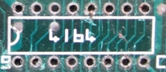
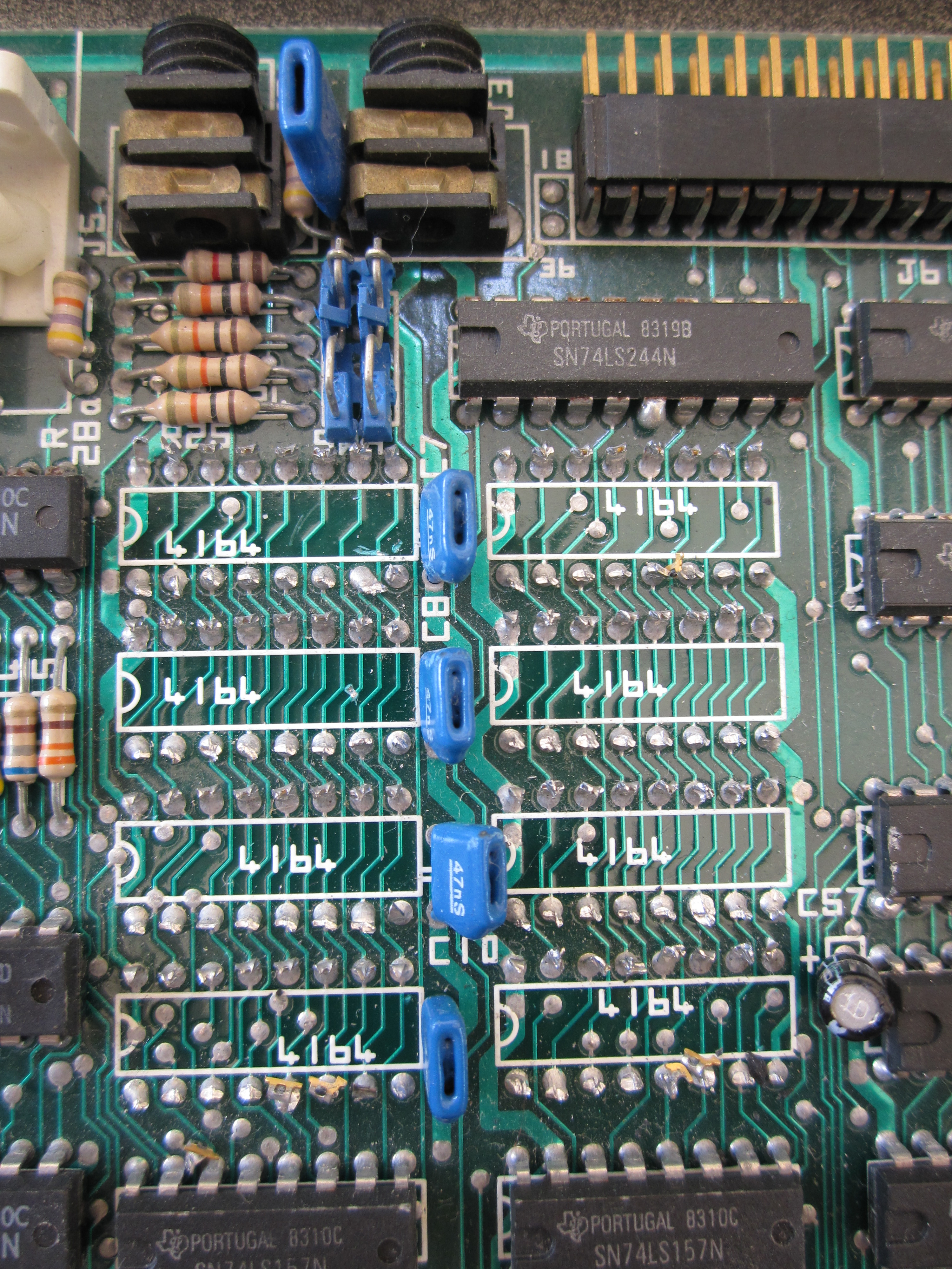
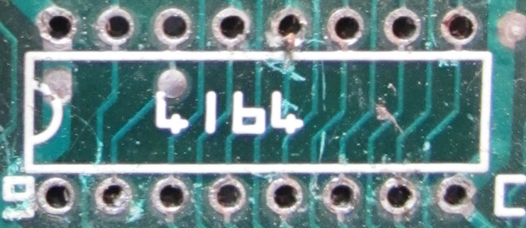
(As an aside, if the chips in those positions had
been 4164 RAM chips, none of this would have been
necessary!) |
 |
| Once the chips have been removed, it is fairly
easy to remove the legs from the IC pin holes using a
micro tip soldering iron. Apply just enough heat to
melt the solder then "flip" the legs out one at a
time using the tip of the iron and a pair of fine
nose pliers if required (the holes will close over as
the solder sets).
|
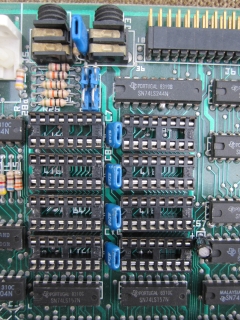
| Once the 8 RAM chips have been
removed, the chip mounting holes can be cleaned up. It is
probably counter intuitive, but applying a little more solder to
the holes will make clearing them easier, so apply a little
solder to reverse side of each pin hole. The solder can then be
removed by reheating them and using a solder "sucker" to remove
the solder and leave an open hole for the new IC socket. |
 |
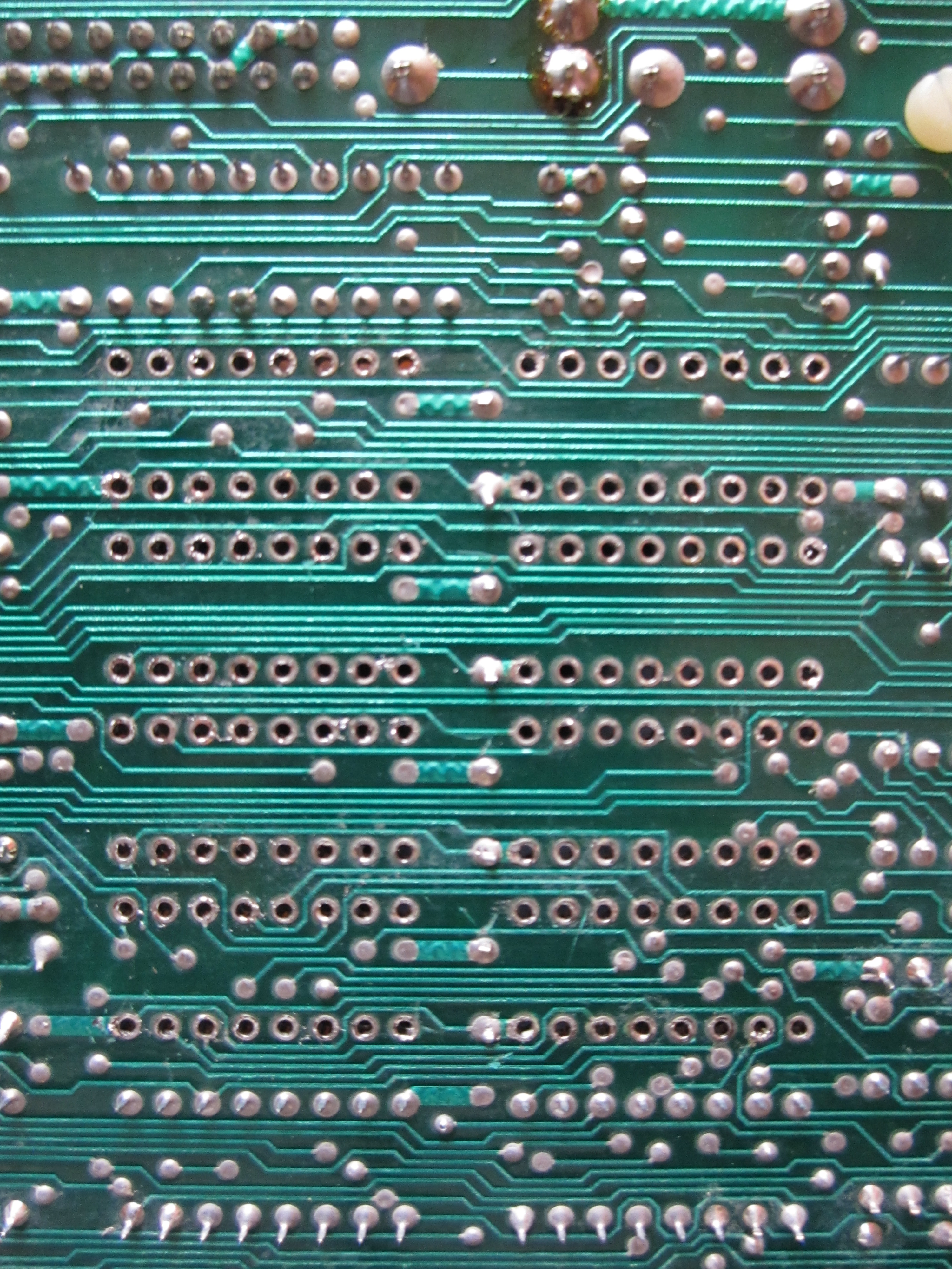
| Underside of the system board with the RAM
removed and the holes cleaned up.
Check both sides of the board and make sure that
there are no remnants of solder bridging any
connections that they shouldn't. |
 |
|
OK, that's the hard work done (I hope!).
The next step is to solder in the sockets for the new RAM.
|
|
 |
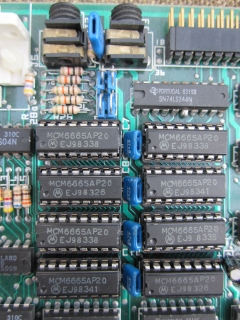
| After a bit of a delay, the shiny new 16 pin DIL sockets
are installed in place of the old RAM.
Ready to install the new RAM chips. |
 |
| New 64Kx1 RAM chips installed in the
new sockets. Ready for testing . . . . .
But . . . . . |
 |
15/08/2012 - Upgrade Failed
The new sockets have been soldered in and the replacement RAM
chips fitted - however, the current status is that
the machine
does not work :-( The initial symptoms were that when the
machine was powered on, the screen had an apparently normal blue
background, but no text was displayed and the speaker emitted a
continuous low frequency tone. Resetting or powering off/on the
machine had no effect on this behaviour on restart.
My initial thoughts were that I probably had a short or dry
joint somewhere around the newly soldered IC sockets. On close
inspection with a lamp and magnifying glass, no problems were
evident, but I cleaned off an excess of residual flux and may
have coincidentally corrected a tiny short between a couple of
pins. In any event, the symptoms changed slightly, the machine
now showed a completely blank (black) screen with the same
continuous tone from the sound chip. The upgrade kit included a
couple of spare RAM chips and I tried swapping out pairs of RAM
chips in turn, in case there was a bad chip installed, but this had no
effect on the fault.
This symptoms, both initially, and after cleaning up the new
IC socket soldering, were identical to those seen by Andy Key.
This is an unlikely coincidence and I therefore believe that the
RAM upgrade kit either has a fundamental flaw in its design, or
a number of the RAM chips in the supplied kits were faulty. [Update
: This was not true - see below]
The only possibility for reviving the machine would appear to
be the new
Memory Card being developed by Andy.
23/10/2012 -
The Interim Solution
I received a
MTX Memory
Card today from Andy Key, removed the 8x64k RAM chips from
the new sockets, connected the new RAM card and powered on the machine - result : the system
works again with 64kB of memory available to Basic programs etc.
Thanks Andy - it is a great relief that I have not "bricked"
the MTX with my attempted RAM upgrade.
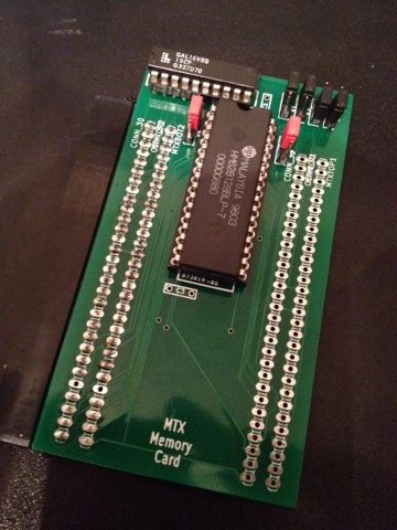
| Here it is :-
a memory upgrade for
the MTX that
works!
This is Andy's prototype board, with
a single edge connector for fitting inside the MTX
case.
|
 |
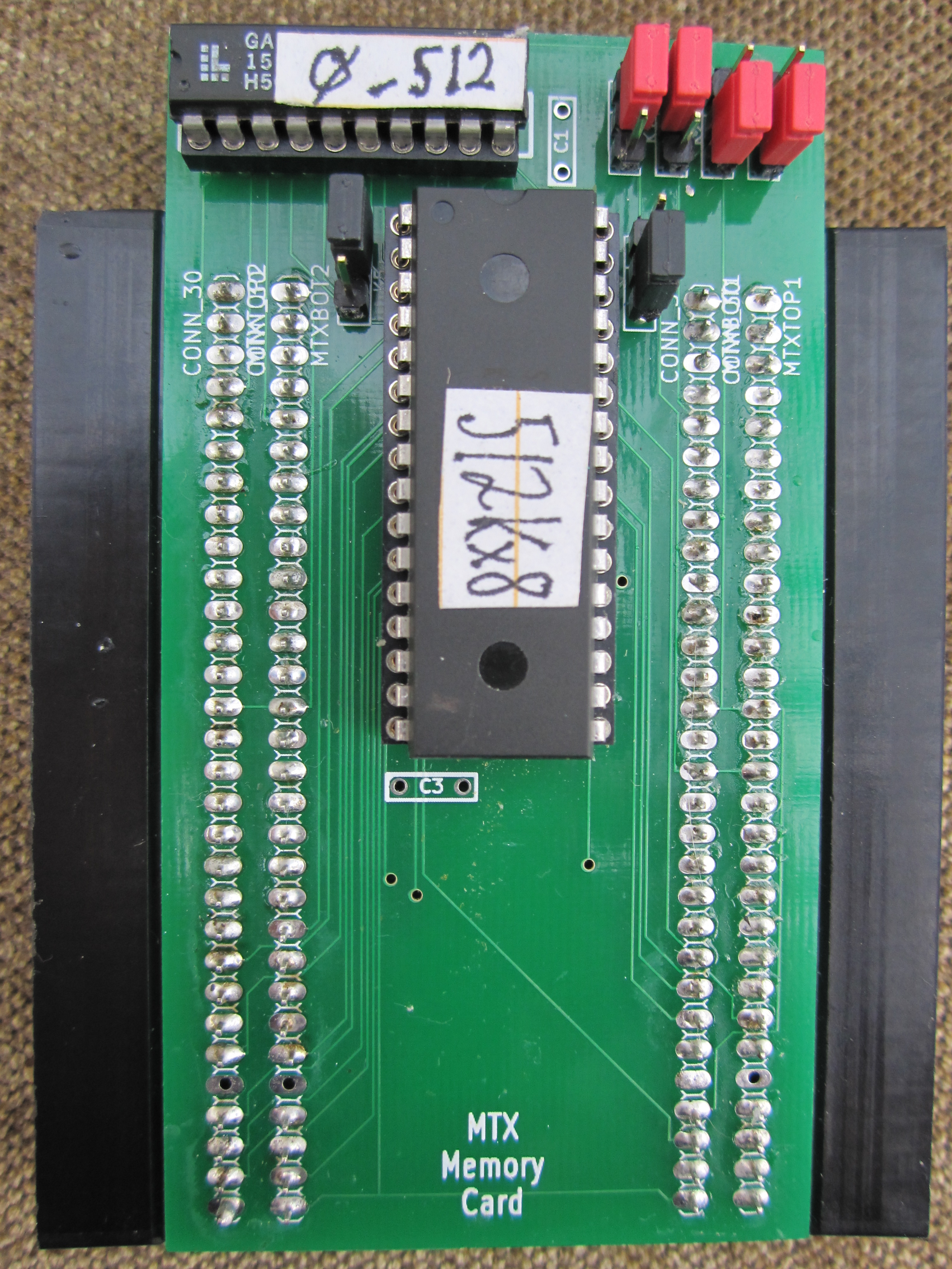
| I still hope to get an FDX unit working again.
If I can do that, I will need to connect the
RS232 board
internally, and as the memory card does not have an
edge connector to support "pass through" of the bus,
I would need to move the memory card to the other
edge of the motherboard, outside the case. This
would require another edge connector on the board.
This is my memory card with 2 edge connectors. |
 |
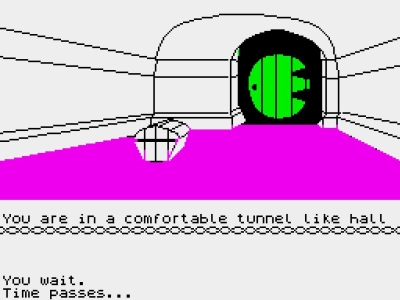
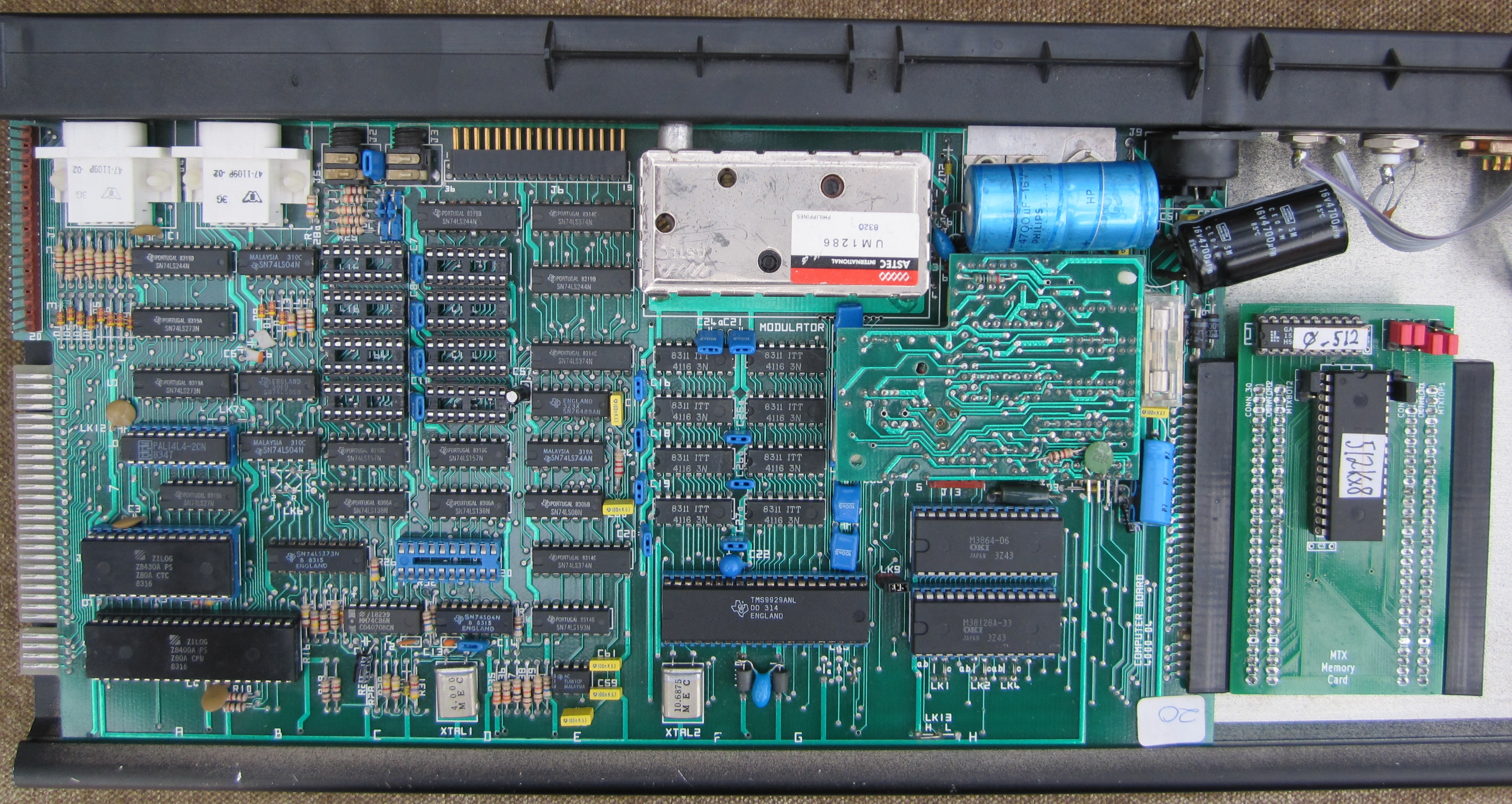
| Here it is, the new memory card installed in my
pseudo MTX512.
Executing "PRINT PEEK(64122)", returns "1",
confirming that there are 2x32K (0+1) pages of RAM
visible to BASIC. (An MTX500 would return "0", for 1
page installed).
|
|
 |
06/08/2014 - The Final Final Outcome
Doesn't time fly? Almost 2 years later and I
have just revisited my failed memory upgrade. Spurred on by
Martin Allcorn's
successful RAM upgrade, using some of the 64K RAM chips
that I had previously tried, I have taken another look at my
"upgraded" board and have found the (self-induced) fault.
I don't know how I missed it previously, but
I found that there was a lack of continuity between pin 12
on all of the RAM sockets, this pin is the A3 address line
and should be connected to all of the RAM chips, I found
that the sockets in positions C2, C3, C4, C5 and D5 were
connected, as were sockets D2, D3 and D4, however, there was
a lack of continuity between these two sets of sockets at
D4/D5.
| The A3 connection between sockets D4 and D5
is on the component side of the board, and
largely invisible once the sockets are mounted.
As it turns out, although my earlier photos did
not highlight a problem, as you can see, the
connection at D4 is definitely suspect. |
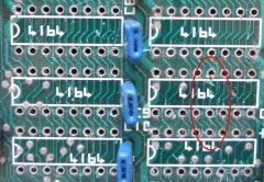 |
| Knowing where to look, it is possible that
the photo shows the track has separated from the
through-hole pad at pin 12 of D4 |
 |
| I was loath to try removing the socket and
trying again, instead, in true Memotech
tradition, I added a yellow wire to the solder
side of the board, linking D4 and D5. Lo and
behold - it fixed it!
|
I didn't take a photo of the
solder side of the board before I reassembled
the computer, I'll take one the next time I have
the computer board out of the case - if I ever
need to. |
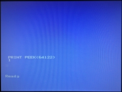
| With the original PAL still in place, the
MTX is configured to have 32K of RAM. As
expected, the
additional 32K is not visible and "PRINT
PEEK(64122)" returns "0". |
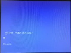 |
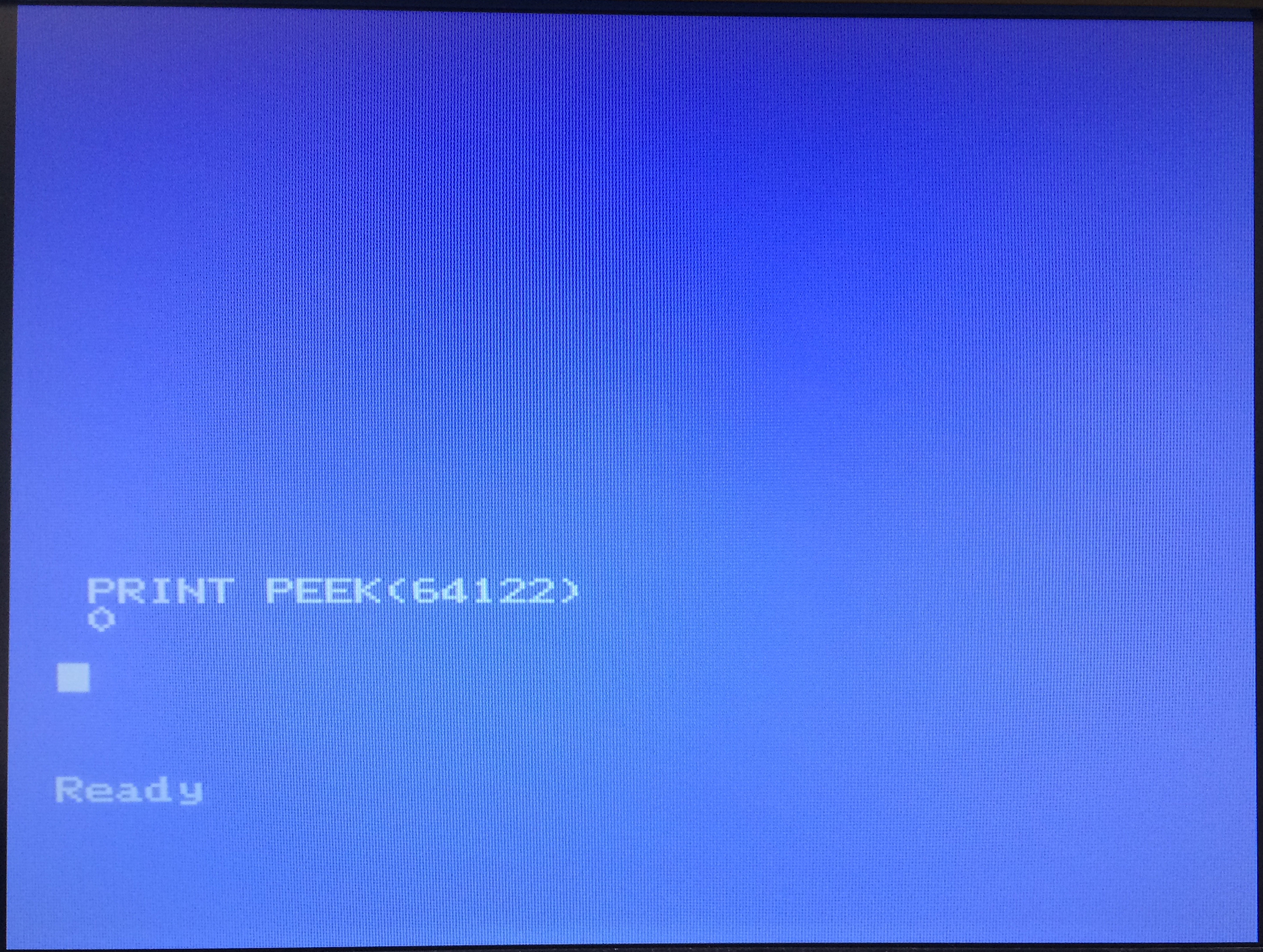
| With the original PAL replaced by the one
that Andy prepared for me, the full 64K of RAM
is now visible. "PRINT PEEK(64122)" returns
"1".
RESULT ! - My "MTX512" that had 32K of RAM now
has "what is says on the tin" - a full 64K of
RAM. |
 |
"Lessons Learned"
-
It is possible to upgrade
from a MTX500 to an MTX512 (or beyond)
-
You do not need an
original Memotech RAM expansion card
-
You do not need to butcher
the MTX500 circuit board
-
You could use the
MTX Memory
Card from Andy
-
Better still, just upgrade to REMEMOrizer
!
< Back to
Memory Repairs >
|


