|
|
|
|
 |
The Memotech MTX Series |
 |
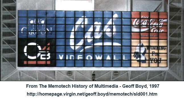
MEMOTECH
Multi-Effect Video Wall
The Distributed Digital Frame Store (DDFS)
The heart of the Memotech Video Wall system is the
Distributed Digital Frame Store (DDFS)
|
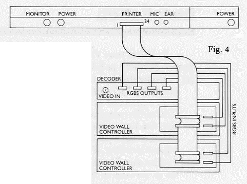
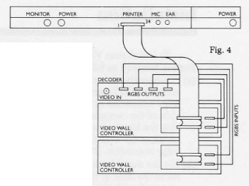
The Video Wall
operator interface, typically a Memotech MTX
computer, is connected to the Video Wall
DDFS controller(s) using a 34-way ribbon
cable between the operator interface parallel
port and the IDC sockets on the rear of the
DDFS.
Each DDFS
has two IDC connections - one for each Frame Store Controller Board
(see below) and two RGBS
connections to the Decoder/Distribution
Amplifier, again, one for each Frame Store Controller.
(See my
Video Wall
Overview page more information on how the
components of the Memotech Video Wall system are
assembled.) |
 |
The major components in the DDFS are :-
Memotech badged
Video Wall systems were available in two versions - the
medium resolution (mid-res) Memopix 1500 (DDFS
1.5) and the high resolution (hires)
Memopix 2000 (DDFS 2.0). Both
systems were capable of 128 independently programmable
modes per monitor but the DDFS 2.0 Frame
Store boards had 4 times the memory capacity of a
DDFS 1.5 board which gave the Memopix 2000
system better resolution and additional special effects
such as distortions, mirror, inverted and
picture-in-picture features.
Cameron badged
Video Walls were also available in two versions - called
System 100 and System 200,
although the Cameron
User Manual only gives a single set of
specifications, it is assumed that the difference
between the System 100 and System
200 was also in the amount of memory on the
Frame Store Memory Boards.
|
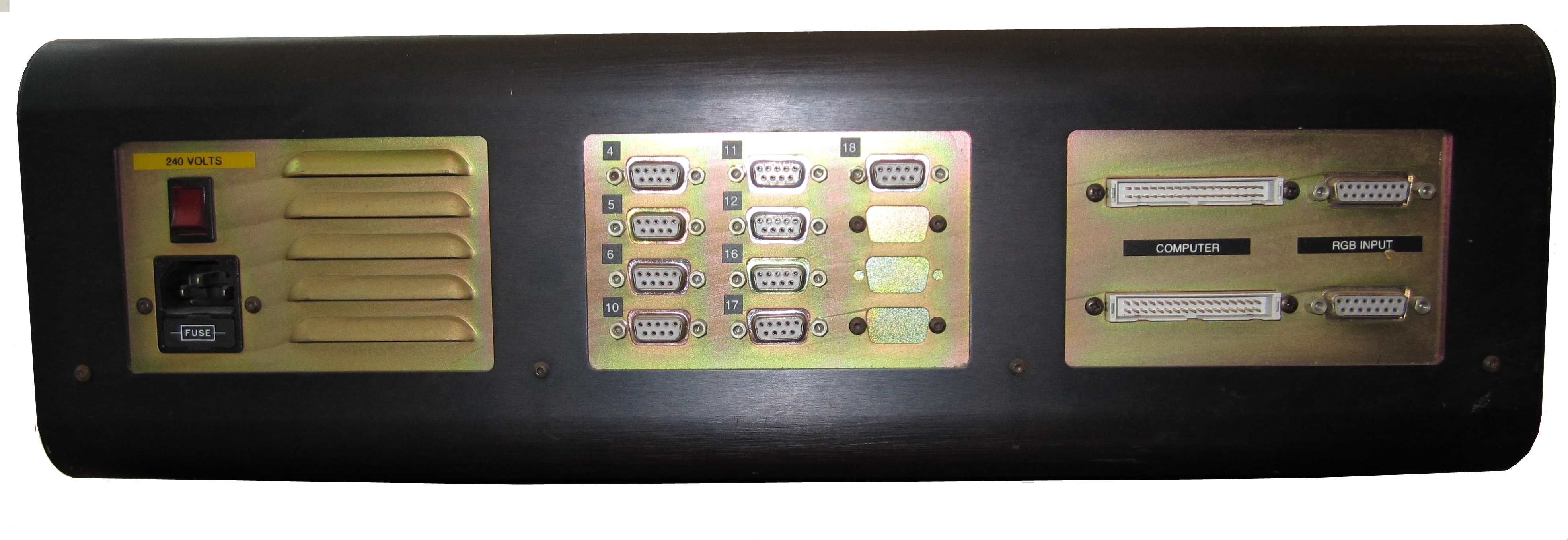
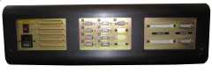
The
DDFS rear panel, showing :-
2 x 15 way ""D"
connectors for the RGBS inputs from the Video Decoder
2 x 34 way IDC
connectors from the MTX Centronics interface
12 x 9 way "D"
connector panel (9 used) for the RGBS video outputs |
 |
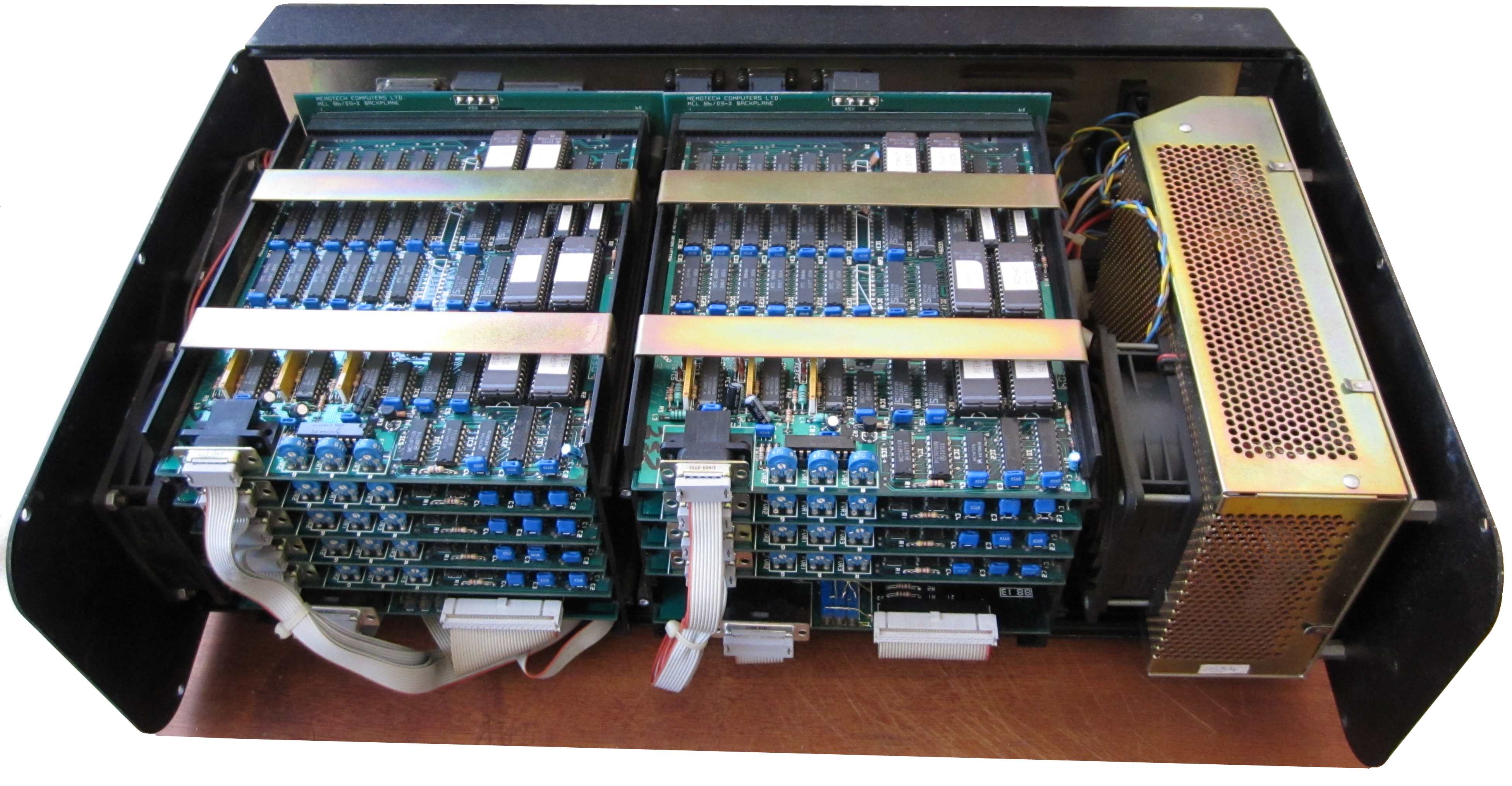
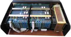
| Internal view from the front of the
DDFS; in addition to the PSU (on the
right), the DDFS houses two 6"
card files.
Connections to the rear panel connectors are
made using the ribbon cables visible at the
front of each PCB. |
 |
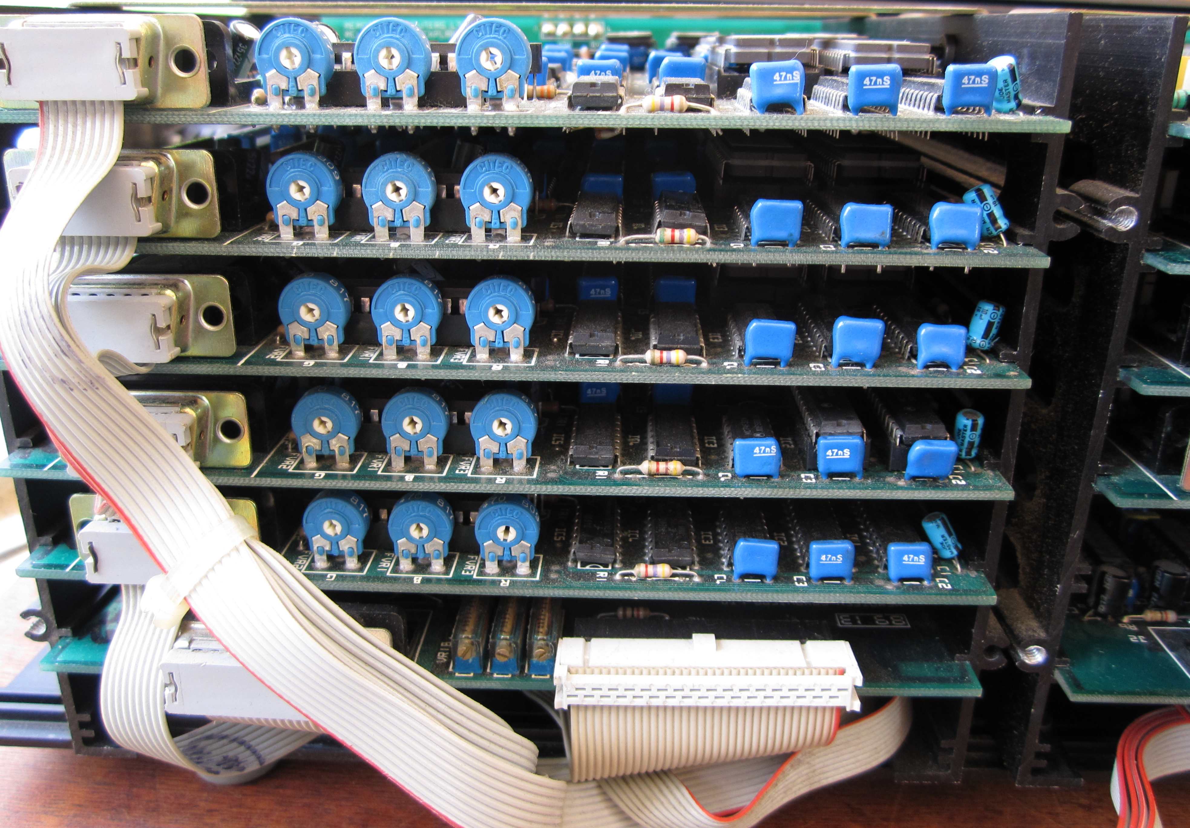
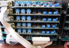
| A close up of the left hand card file, the
upper five boards are the Frame Store Memory
Boards. Each FSMB connects to a
dedicated monitor via the small ribbon cables to
the 9-way "D" connectors on the rear panel.
The lower board is the associated Frame Store
Controller Board ; the 34-way ribbon cable
connects to the MTX computer via the 34-way IDC
connector and the 15-way ribbon cable connects
to the RGB input 15-way "D" connectors - both on the rear
panel. |
 |
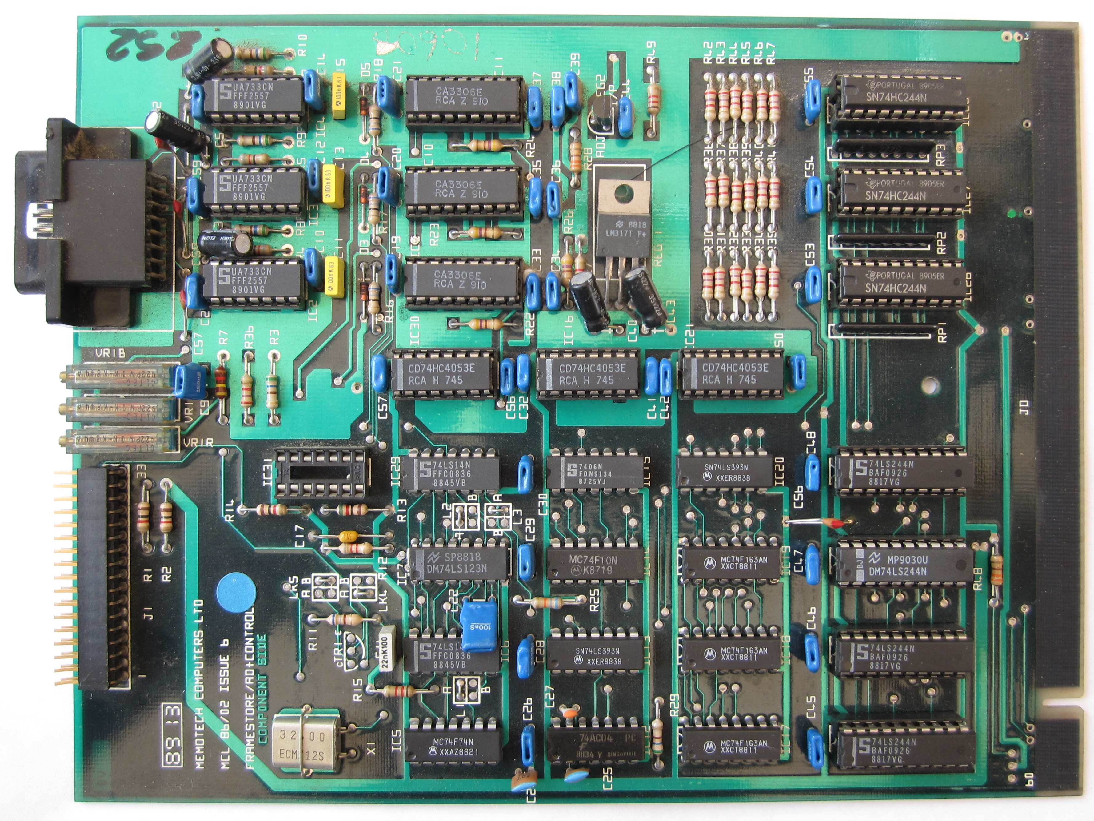
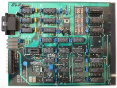
Frame Store
Controller Board (FSCB) Up to two
FSCBs can be installed in a single DDFS
and each can control up to five Frame Store Memory Boards (FSMB).
| You can see that the FSCB is
pretty much laid out in two halves.
On the upper half of the board, each colour
of the RGB video signal fed to J2 is amplified
by a UA733 video amplifier and then digitised by
a CA3306E 6-bit A/D converter before being made
available to the frame store memory boards
through the backplane.
The lower half of the board is associated
with the command signals fed to J1 from the
computer which are then processed before being
made available on the backplane. |
 |
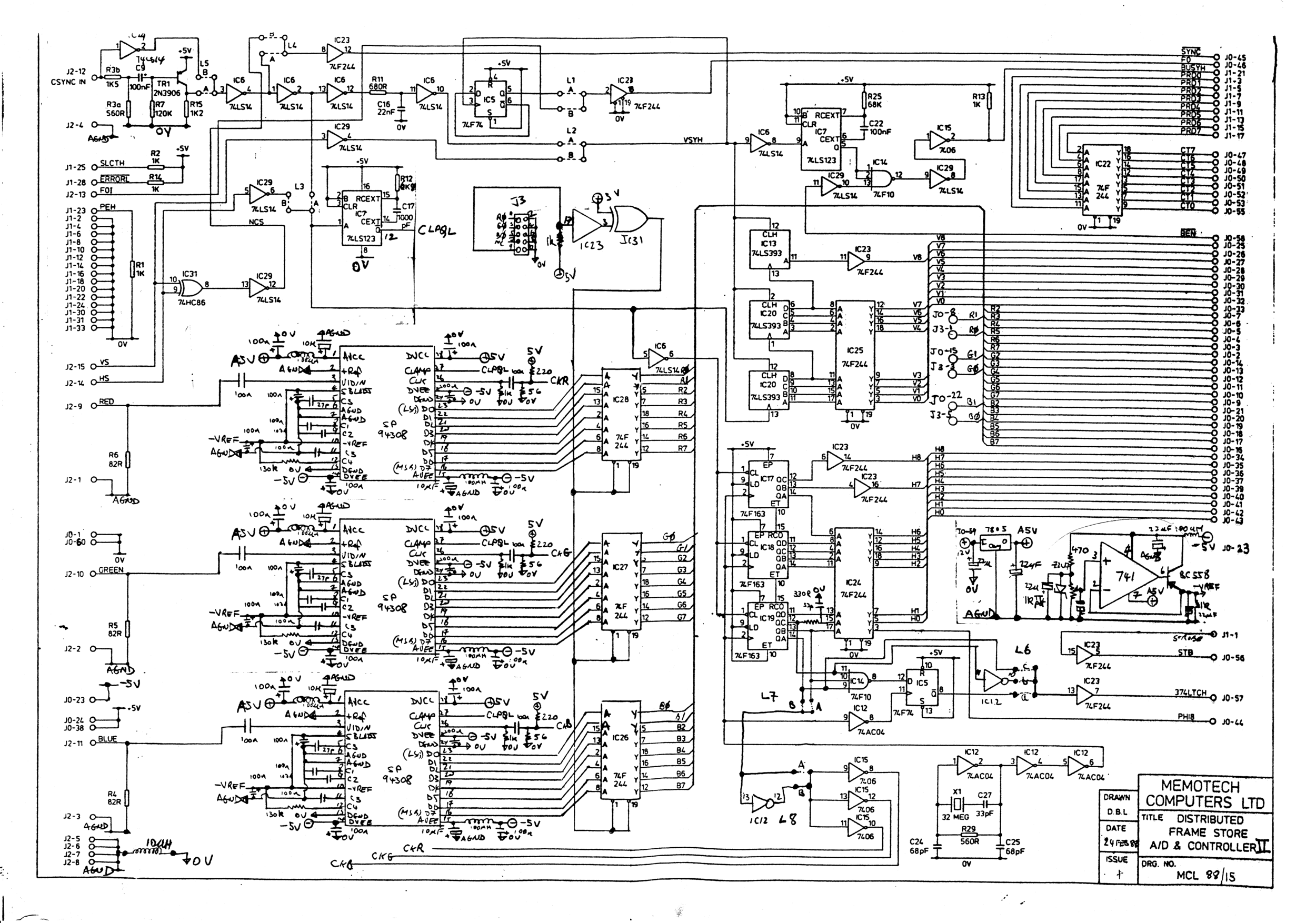
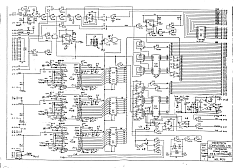
Memotech schematic for the FSCB - Mark II
Version (1988)
This is a later version of
the board than installed in my Video Wall
hardware and includes a
Plessey SP94308 8-bit Video DAC which
replaces the UA733/CA3306E Amplifier & ADC
components used in the earlier board.
Courtesy of Tony Brewer |
 |
| |
|
|
To be
continued . . . . . . |
Frame Store Memory Board (FSMB)
Communication between the FSCB and the
FSMBs is via the back plane of the 6" card
file, as the card file has a total of six slots, each
FSCB can control up to five FSMBs.
Therefore a single DDFS can control a
maximum of 10 monitors and larger Video Walls were built
using additional DDFSs as required, up to
a maximum of 8 giving 128 monitor outputs.
Unfortunately, my DDFS is the med-res
version using DDFS 1.5 boards having 16k
x18 RGB bits per frame store. DDFS Version
2.0 boards have 64k x18 RGB bits per frame store.
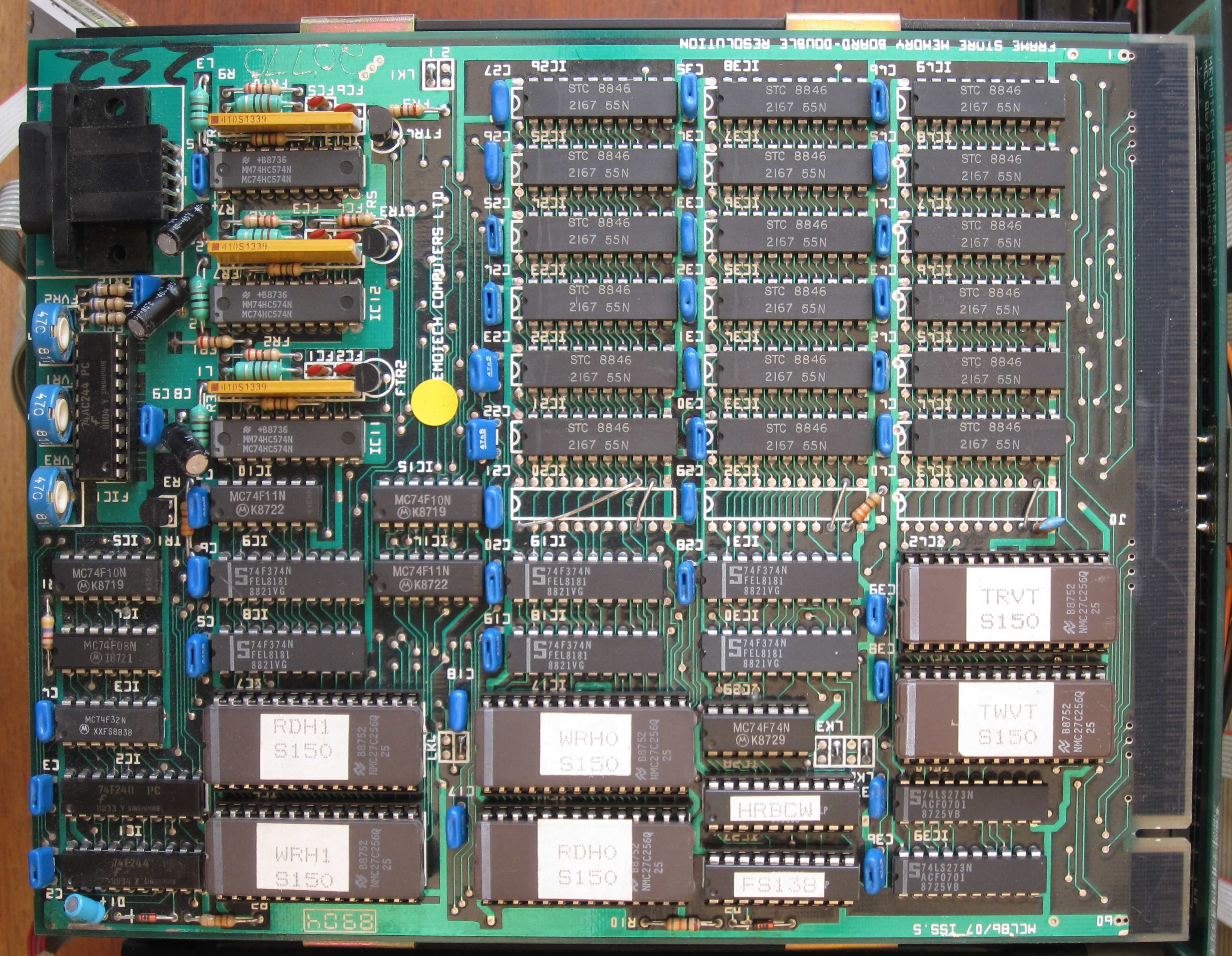
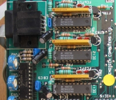
| As the name indicates, the FSMBs
stored and manipulated the image data. The
18 SRAM chips on my DDFS 1.5
boards are ST 2167-55Ns, below each column
of RAMs is an empty location for an
additional RAM chips for each colour which
would have allowed for 7-bit video, but as
the A/D convertors on the FSCB
was only 6-bits, there was no point in
installing the extra memory chip. |
 |
| |
|
|
To convert the video information back to
analogue RGB, there are digital-to-analogue
converters adjacent to the 9-pin "D"
connector - J1.
As Geoff Boyd recalls, "these use a
[Memotech designed] custom resistor network
and AC574 (HC574s worked as well) to make a
Video speed DACs. That was a trick we kept
up our sleeve, together with using tri-state
AC244s and a PAL (ULA) to do variable RGB
output filtering and colour washes. It gave
us a competitive edge by making the product
highly affordable because high quality
triple video DACs in those days costs
upwards of 50 pounds each compared to less
than a couple of pounds for the entire
DDFS RGB output solution." |
 |
| |
|
| |
|
| To be
continued . . . . . . |
|
 |
|