|
 |
The Memotech MTX Series |
 |
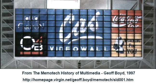
MEMOTECH
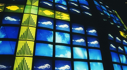
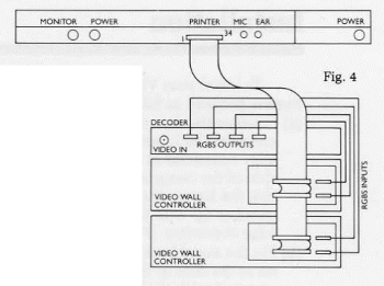
 Multi-Effect Video Wall
Decoder / Distribution Amplifier
|
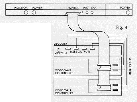
Each
DDFS
has two IDC connections - one for each Frame Store Controller Board
(see below) and two RGBS
connections to the Decoder/Distribution
Amplifier (DDA), again, one for each Frame Store Controller.
The DDA
accepted a
PAL or
NTSC
composite video signal and decoder it to
generate
RGB video signals for the DDFS.
(See my
Video Wall
Overview page more information on how the
components of the Memotech Video Wall system are
assembled.) |
 |
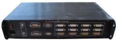
The major components in the DDA are :-
My selection of Video Wall hardware has 4 DDA
modules, these are unlikely to have come from a single system - a typical Video Wall system would have used a single
DDA, taking one or two video inputs
for display on the Video Wall. Additional
DDAs could be added to facilitate the use of additional
video feeds.
| Video Decoder
/ Distribution Amplifier |
|
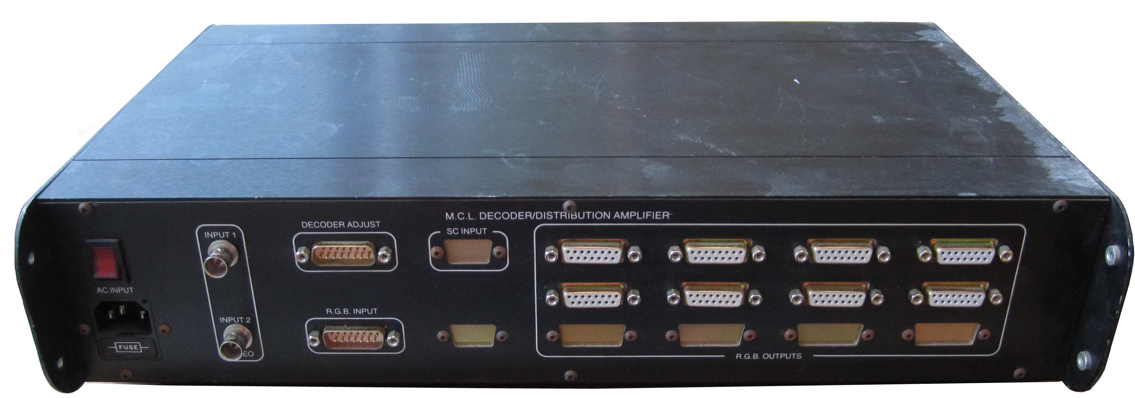
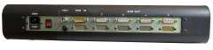
One of my PAL Video Decoder / Distribution
Amplifier (DDA) modules.
This
is a Memotech branded unit and would have been
produced after the Memotech exclusive
distribution agreement with Cameron had
ended. |
 |
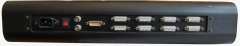
| This DDA has two composite and
one RGB video input, an external Decoder
Adjust connection and eight RGB video
outputs for use by up to four Video Wall
DDFS controllers |
 |
|
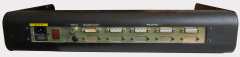
The
rear panel of another of my DDA,
this one has two composite and one RGB video
input, no Decoder Adjust connection and eight
RGB video outputs.
This
DDA is a Cameron branded unit. |
 |
|
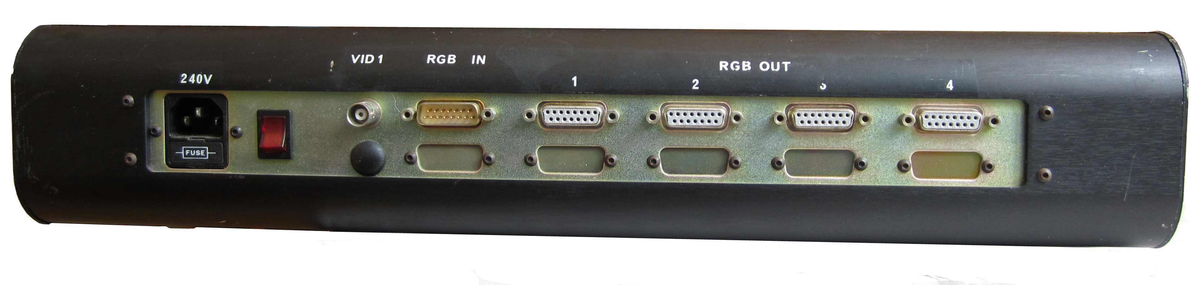
Another model of DDA, this one has a single
composite video input, no RGB input and four RGB
video outputs. The inverted "RGB input"
connector is actually for a Decoder Adjust
dongle.
This
DDA is a Cameron branded unit. |
 |
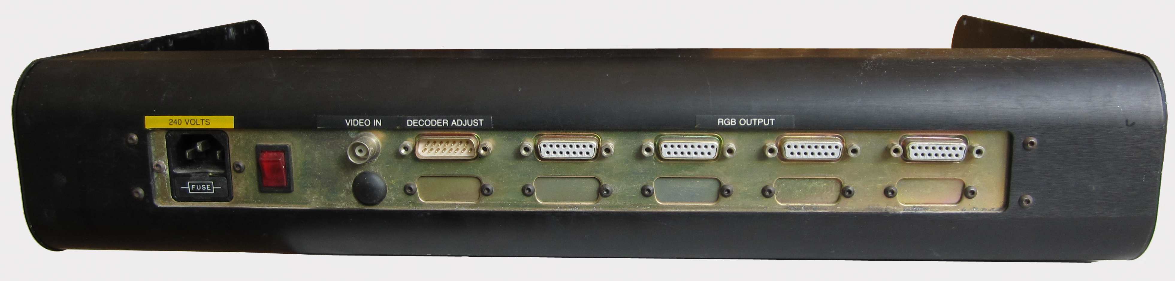
| Another DDA, with the same I/O configuration
as the one above. This unit is labelled as a
Memotech PAL DEC 15 |
 |
|
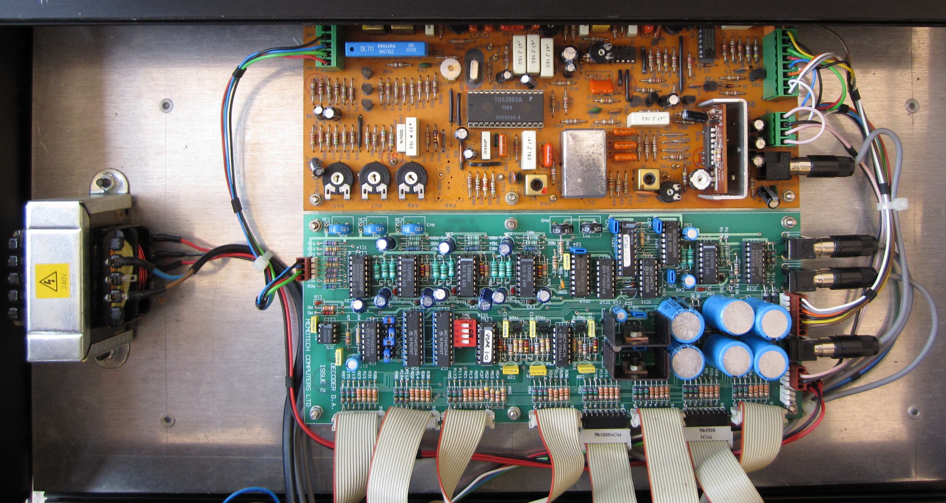
Although they
are all slightly different, each of my DDAs includes
the same type of PCBs - a
PAL Decoder and a
Distribution Amplifier.
Some of the units have power supplied from an AC
transformer with DC regulation done on the
Distribution Amplifier board and others have
separate DC power supplies. |
 |
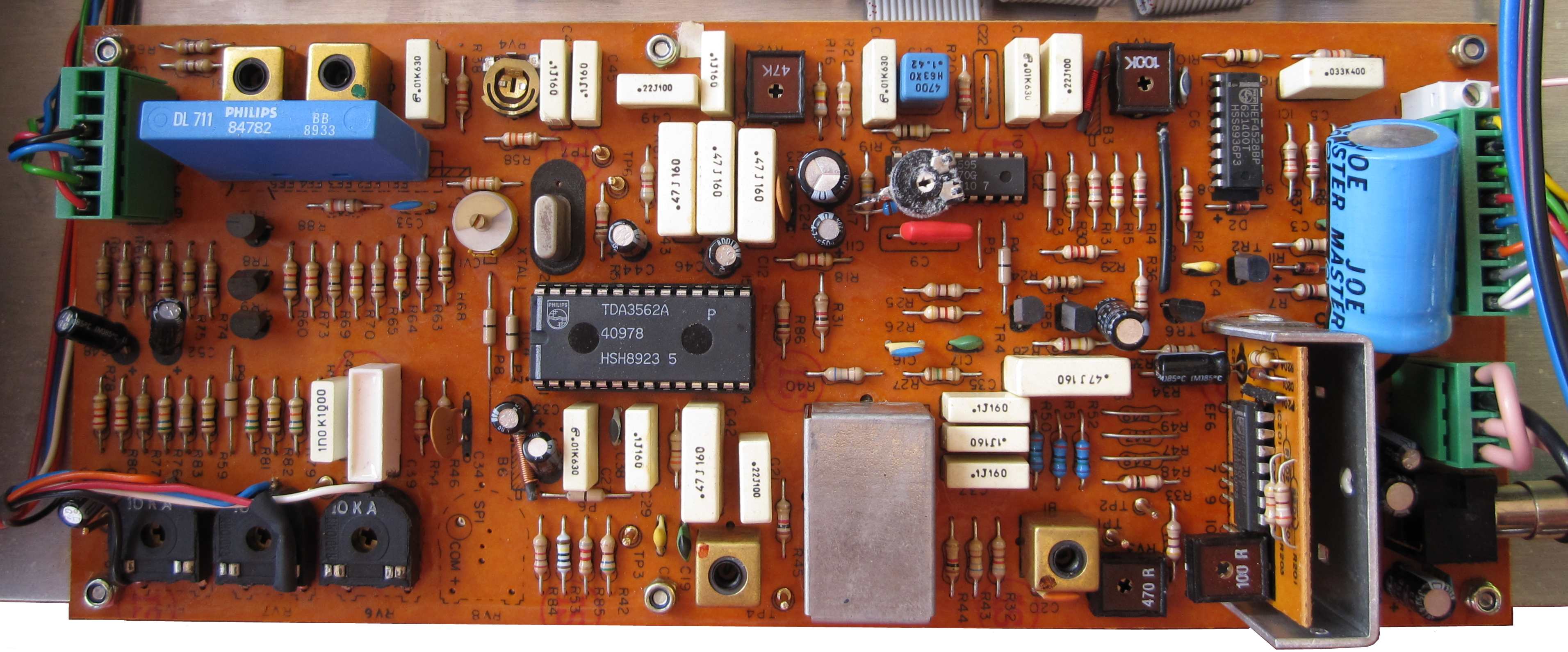
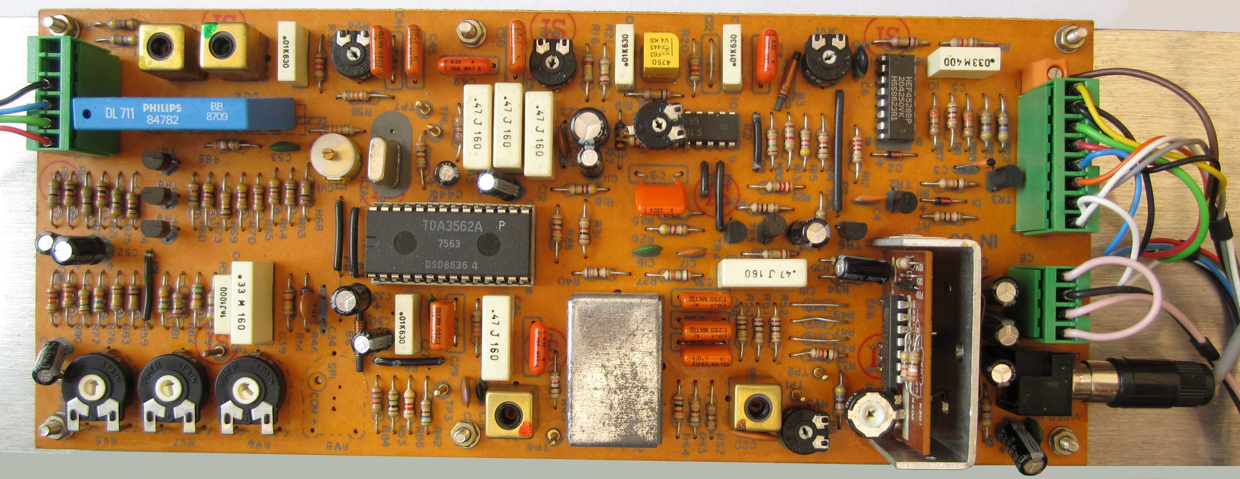
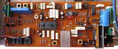
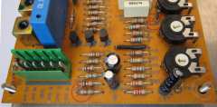
Video Decoder Board
The video decoder boards were one of the
very few circuit boards in the whole Memotech range that
were not designed and built by Memotech at the Witney
factory. Although the decoder boards do not have any
markings identifying the manufacturer or model number,
Geoff (Boyd) has advised that they were "a standard part
manufactured by
Hantarex - a CRT monitor company out of Italy with
strong operations in UK catering to the pub video games
machine market".
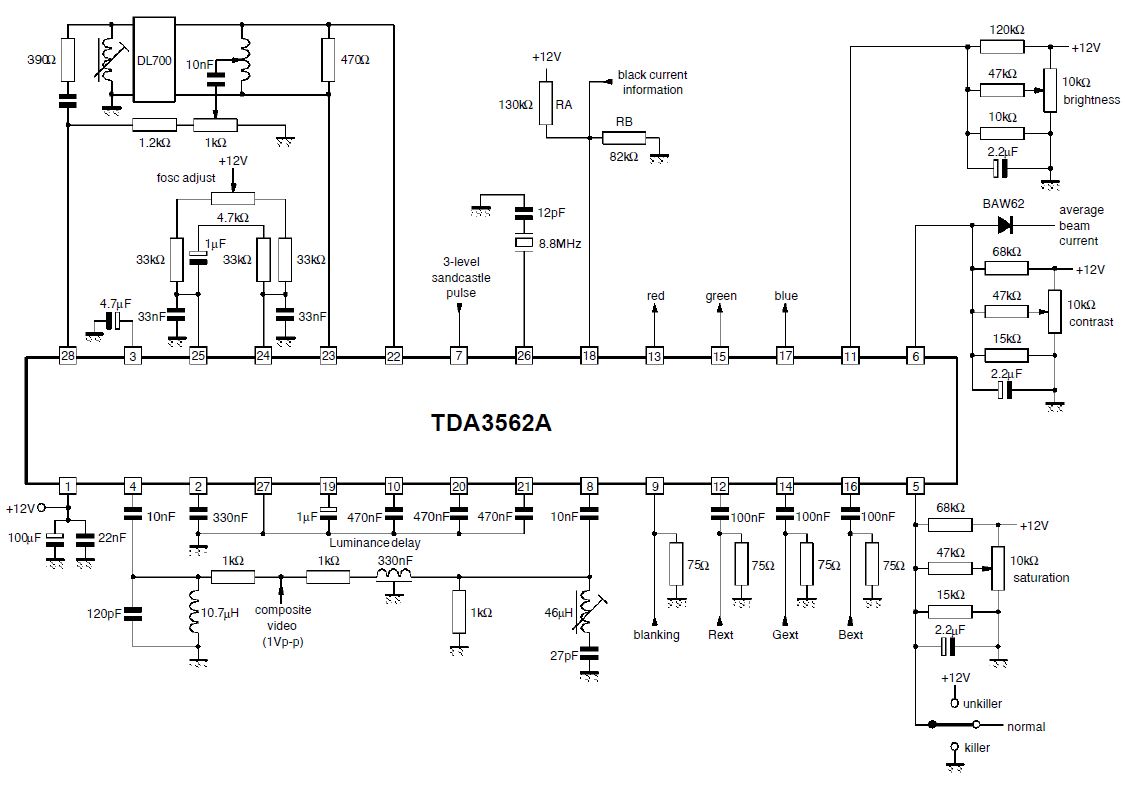
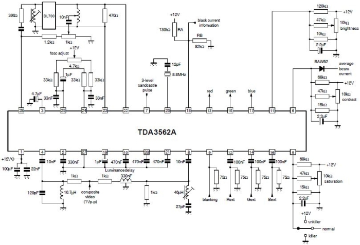
| The Hantarex decoder board is
based around a ST
TDA3562A "PAL/NTSC One-Chip Decoder". |
 |
| What follows is my
attempt to understand the operation of the
decoder board, it is based on my reading of the
TDA3562A datasheet and various web searches
intended to give me enough information to
reconstruct the circuit diagram. It it more than
likely to contain errors due to my lack of
knowledge in this area - if you spot any, please
let me know. |
| Geoff also recalls that "decoder
design follows the TDA3562A data sheet with the
addition of a flywheel sync circuit which was
very useful for stabilizing sync separation from
the composite input signal. Hence although the
MTX Video Wall worked with composite sync (CSYNC)
we preferred to regenerate that CSYNC from the
Hantarex HSYNC & VSYNC which were flywheel
stabilized." [Random pulses due to noise and
other interference are sometimes present on a
composite video signal. The principle of
flywheel synchronisation is similar to that of a
mechanical flywheel, which, due to its large
momentum, maintains an average speed unaffected
by random changes. A flywheel sync circuit
maintains an average frequency of the sync
pulses by monitoring and taking the average
frequency of a number of incoming line pulses so
that a random pulse will have little effect on
the frequency.1] |
 |
|
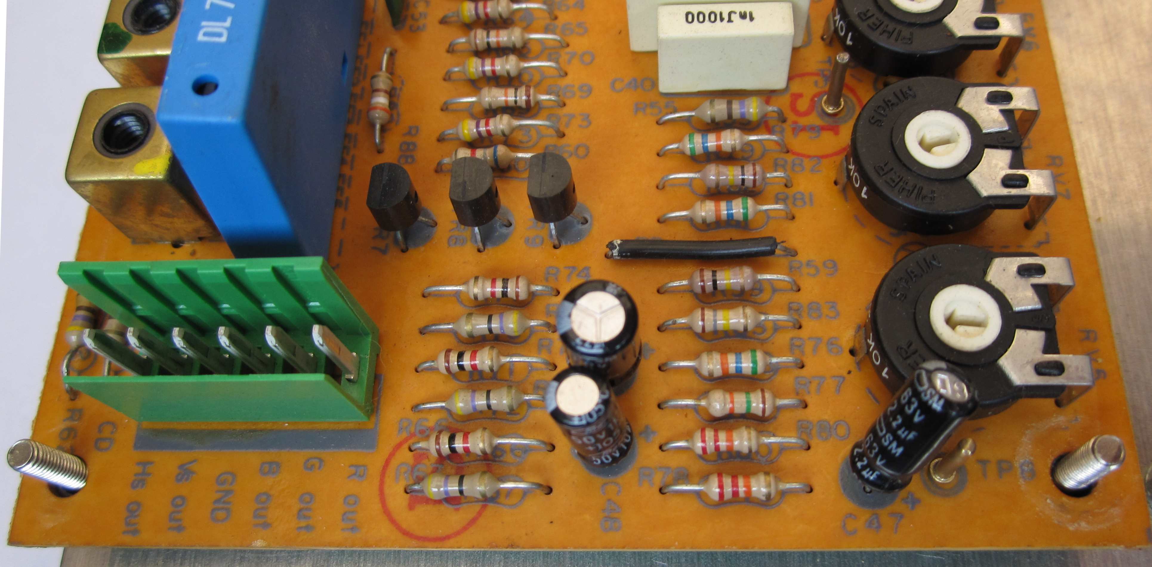
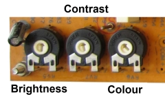
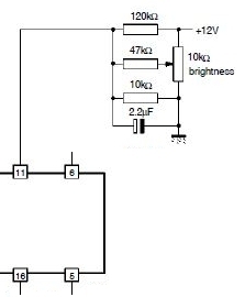
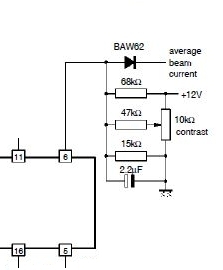
The
three large variable resistors on the lower left
hand corner of the board are variable resistors
for adjustment of brightness, contrast and
colour.
In
the example above, you can see a number of wires
attached to the variable resistors, these go to
the "Decoder Adjust" connection on the rear
panel. This allowed connection of a fine tuning
"dongle", enabling colour matching to be done
without opening up the case. |
 |
|
 |
 |
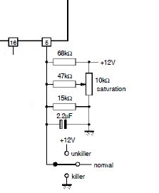 |
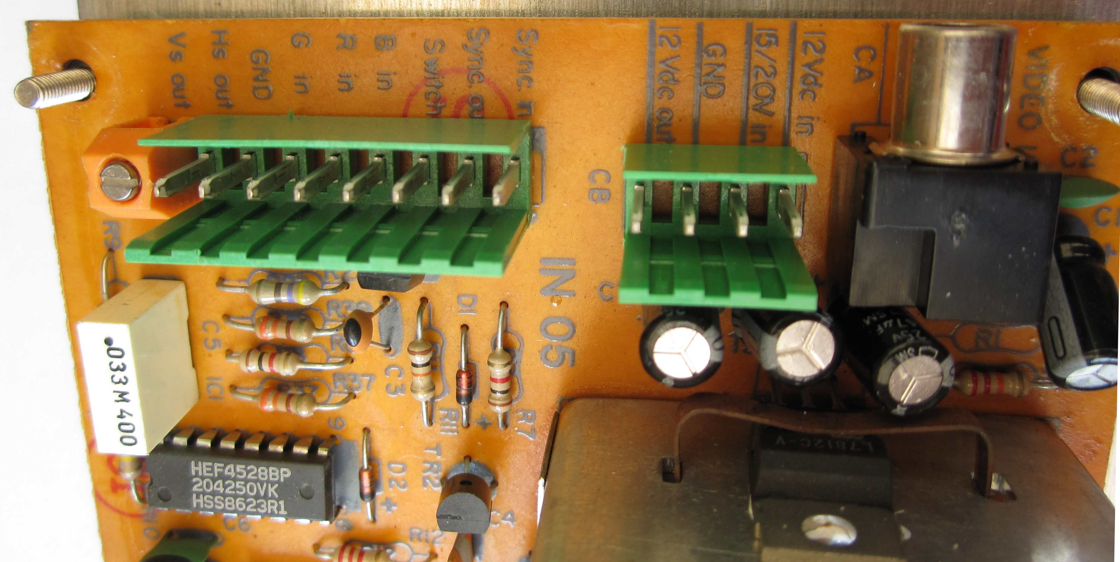
| As well as a phono plug
connection for a composite video input, the
decoder board has additional terminals for
an RGBS video input. The same connector has
Horizontal (HS) and Vertical (HS) sync outputs,
generated on the board from the composite sync
input and the flywheel sync circuit described
earlier.. |
 |
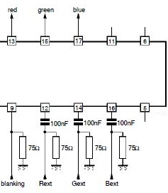
| The decoder board has a 6 pin
connector taking the R, G, B signals to the
distribution amplifier board, this connector
also has HS and VS output signals - which are
not used in the DDAs. You can see that
the variable resistors on this board do not have
the wiring for connection of the external decoder adjustment tool. |
 |
| The RGB outputs from the decoder
board are derived directly from the TDA3562A on
pins 13, 15 and 17.
An external RGB signal, if used, would be fed
to pins 12, 14 and 16 of the TDA3562A. |
 |
|
To be
continued . . . . . . |
|
| |
|
| |
|
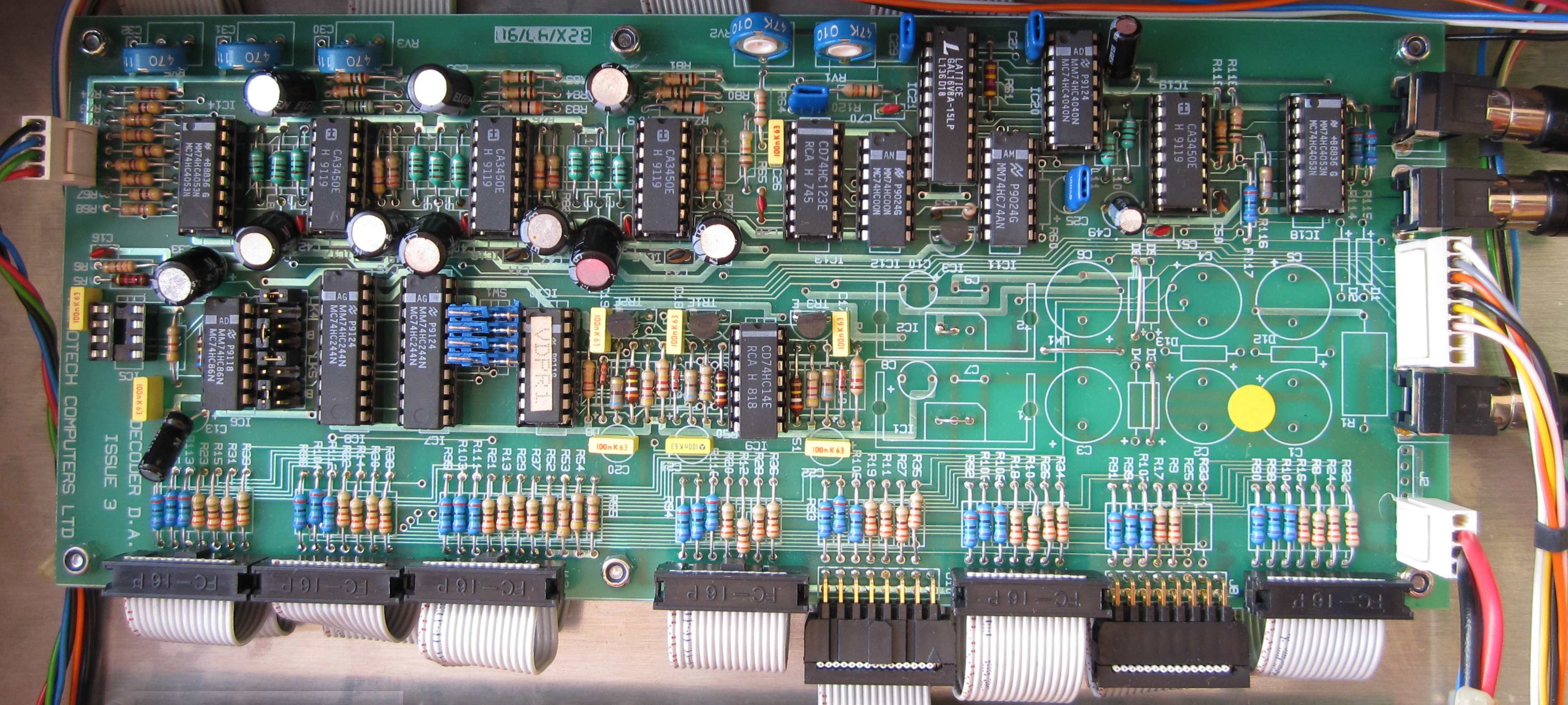
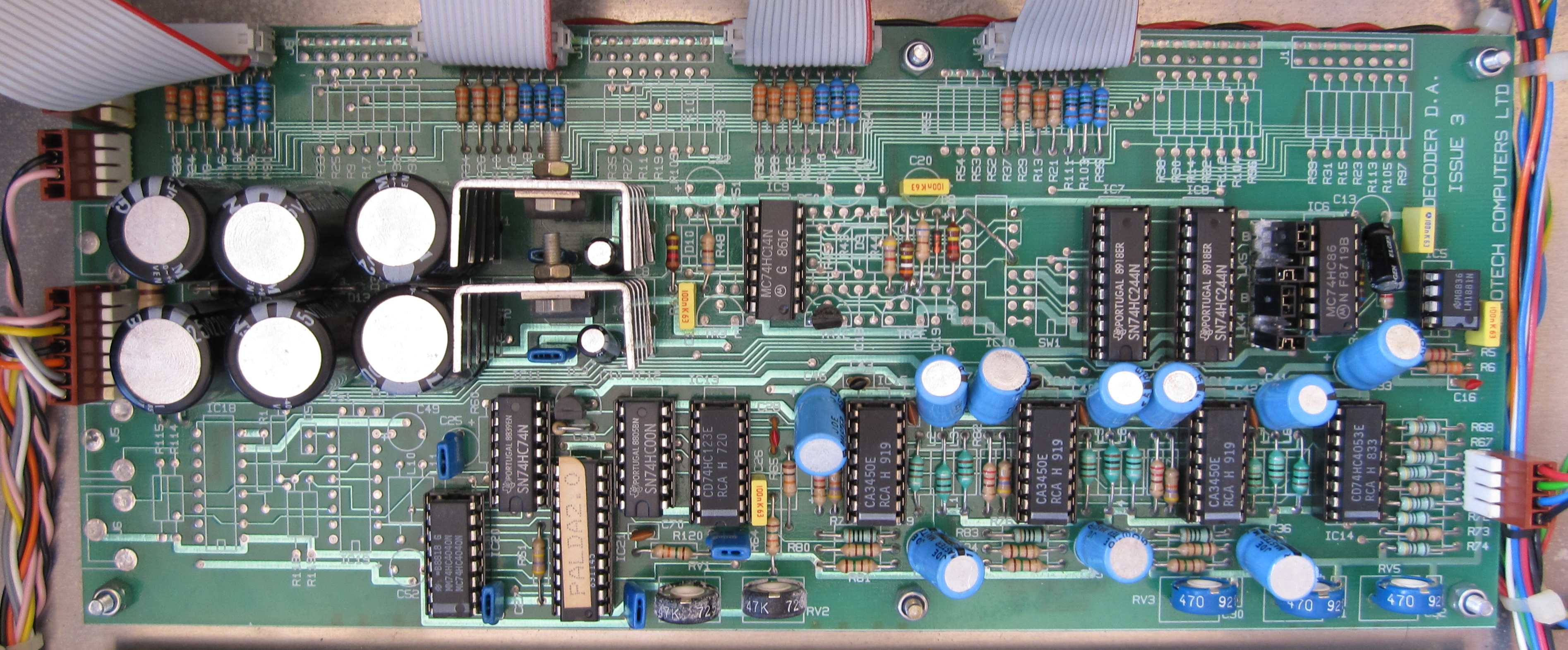
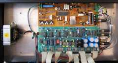
Distribution Amplifier Board
To be
continued . . . . . .
| The other board in the DDA is a Distribution
Amplifier - it takes the RGB signal from the
decoder, amplifies it, and, depending on the DDA
model, splits the signal into 4 or 8 outputs.
Some of my DDAs have two composite inputs
connected from the rear panel, with a single
composite output to the decoder board, on
others, the single composite input connects
directly to the decoder board. |
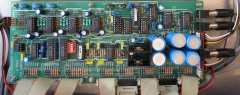 |
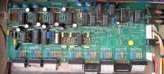
| This DDA is powered using a mains
transformer which supplies low voltage AC to the
DA board. At the right hand side of the board
you can see the large capacitors and voltage
regulators which provide stabilised DC voltages
(+12,+5, -5) to the DA and Decoder boards. Other
DDAs use a 30W Skynet SNP-3032 to provide the DC
voltages and the DA board has the power supply
components omitted. |
 |
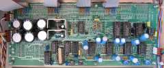
| Another version of the DA has the power
supply components, but not the composite video
input connections or associated electronics. |
 |
| |
|
| |
|
| |
|
1. Newnes "Guide
to Television & Radio Technology", by K.F. Ibrahim,
Elsevier, 2007, ISBN : 978-075068-165-0
(Some of the Video wall information comes courtesy
of Geoff Boyd, 2012/2013, from his recollection of the
Memotech Video Wall)
|