|
Opening the case |
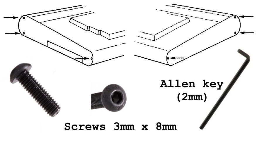
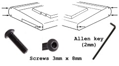
| The two halves of the case are secured by six,
3mm socket head machine screws, three through each
end plate.
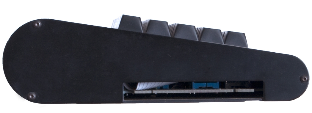
The front edges of the two halves of the case
have interlocking profiles that allow the keyboard
to be swung upwards like a hinge. |
 |
| Step 1 Using a 2mm
Allen
key, remove the three screws from the right and
left hand sides of the MTX. |
 |
| Step 2 Lift the MTX keyboard at the
rear, just above the plastic panel, taking
care not to put strain on the keyboard
interconnecting cable. |
 |
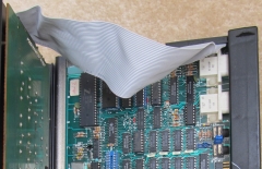
| This photo shows a ribbon cable attached to the
MTX computer board and to the left hand side of the
keyboard. This cable is not the original MTX one,
the Memotech cable is shorter and you will not be
able to raise the keyboard to the same extent as in
this photo without disconnecting the cable first.
(Photo courtesy of Martin Allcorn) |
 |
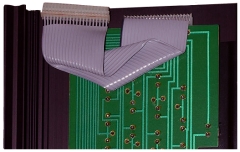
| Another view of Martin's non-standard MTX
keyboard interconnecting cable. (Photo courtesy of
Martin Allcorn) |
 |
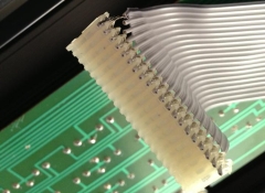
| This photo shows the underside of the keyboard
with an original Memotech ribbon cable attached. The
Memotech cable is
somewhat unusual - unlike a more typical
IDC cable, the ribbon is not supported by the
connectors, instead, each core is stripped out from
the ribbon 5-10mm from the connector.
(Photo courtesy of John Hancock) |
 |
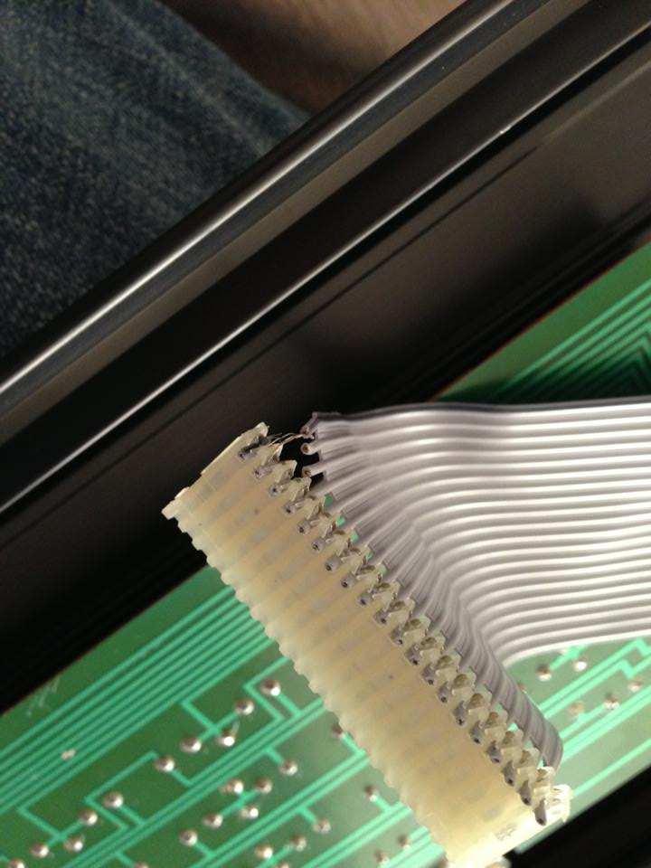
| Step 3 Gently ease the keyboard
interconnecting cable from the mother board
connector, always using the connector - do not
pull on the ribbon cable.
The photo shows the type of cable damage that
can result if care is not taken in opening the case
or disconnecting the keyboard cable.
(Photo courtesy of Andy Garton) |
 |
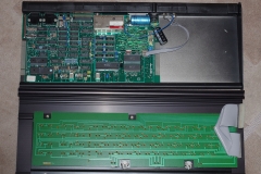
| Step 4 After the cable has been
disconnected from the computer board, the keyboard
is released from the base by sliding it completely
to the left or right, leaving the MTX is two halves
as shown here.
(Photo courtesy of John Hancock) |
 |
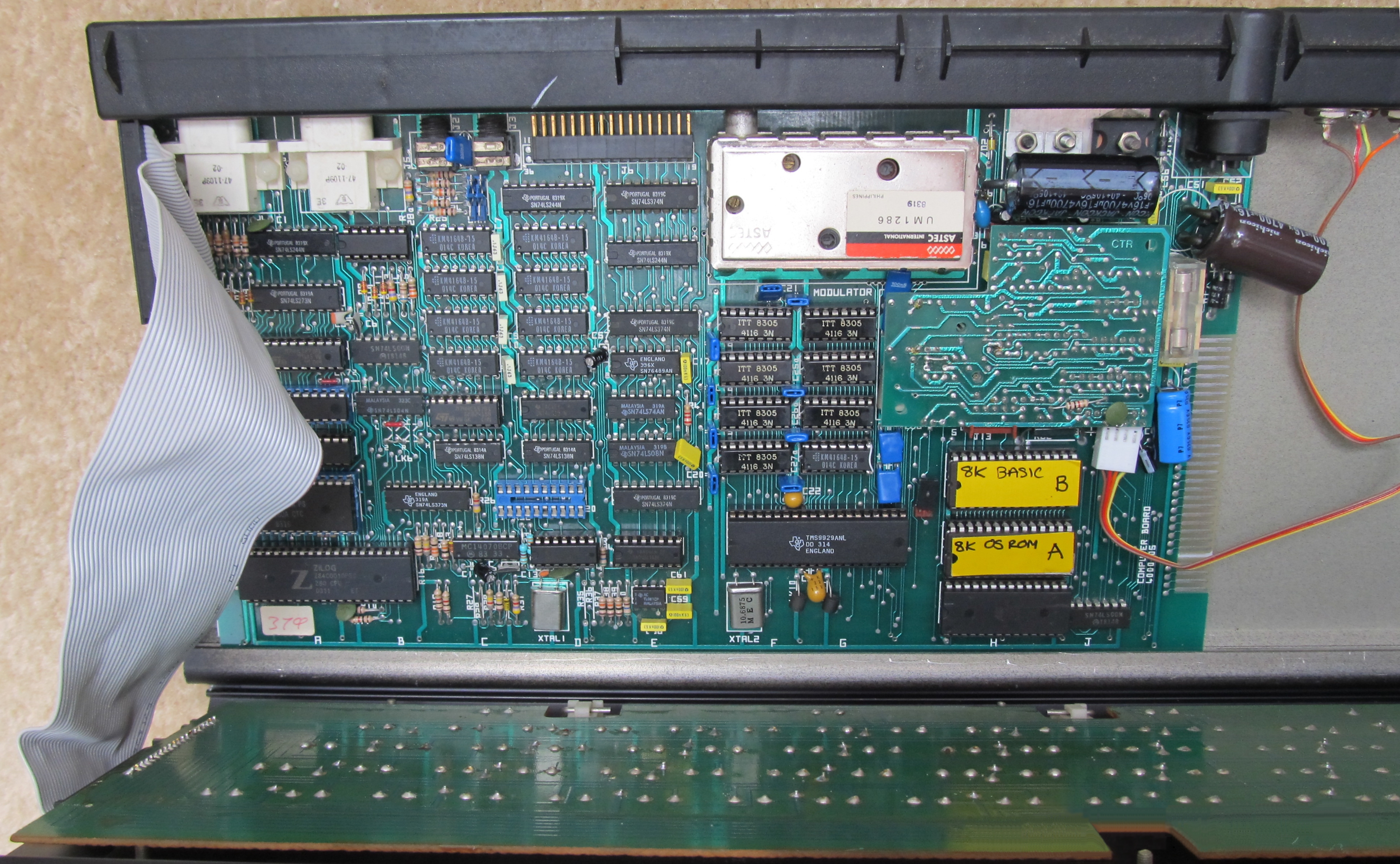
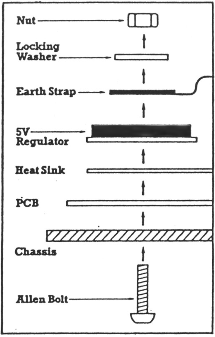
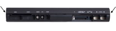
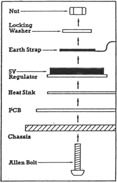
If you need to go further and remove the MTX
computer board, you need to remove the single bolt
that goes through the bottom of the case. The bolt
passes through the elements shown in this sketch
from the Service Manual.
As you can see in
the photos on this page, the hex nut is directly
below C56, the large 4700uF capacitor beside the UHF
modulator. This can make removal of the bolt/nut a
little awkward.
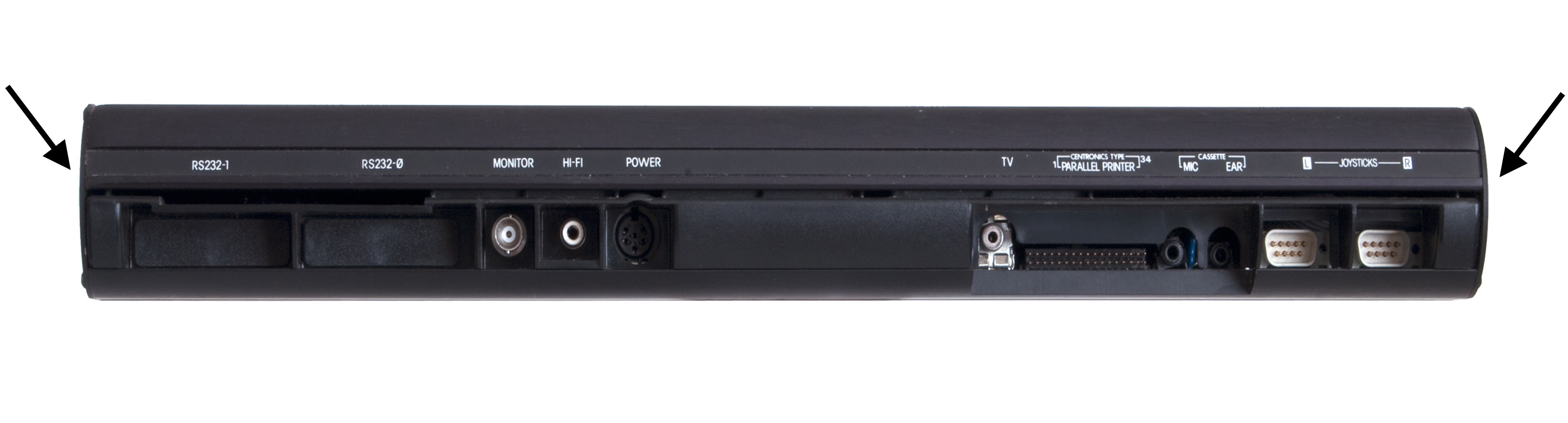
Note: some
MTXs have been found to be missing the earth strap
that should connect to the ground terminals of the
connectors on the back panel. If it is missing, the
quality of the video signal can be degraded.
With the screw and earth strap removed, the
PCB with the rear plastic trim still attached can be
slid out from the case bottom.
Note:
There are usually a couple of small rubber squares,
like those often found as feet on the bottom of the
case, sat between the PCB and the case. These can
sometimes foul on the solder connections on the
bottom of the PCB. |
 |
| |
|
| |
|
|
Installing / Removing Option
Boards |
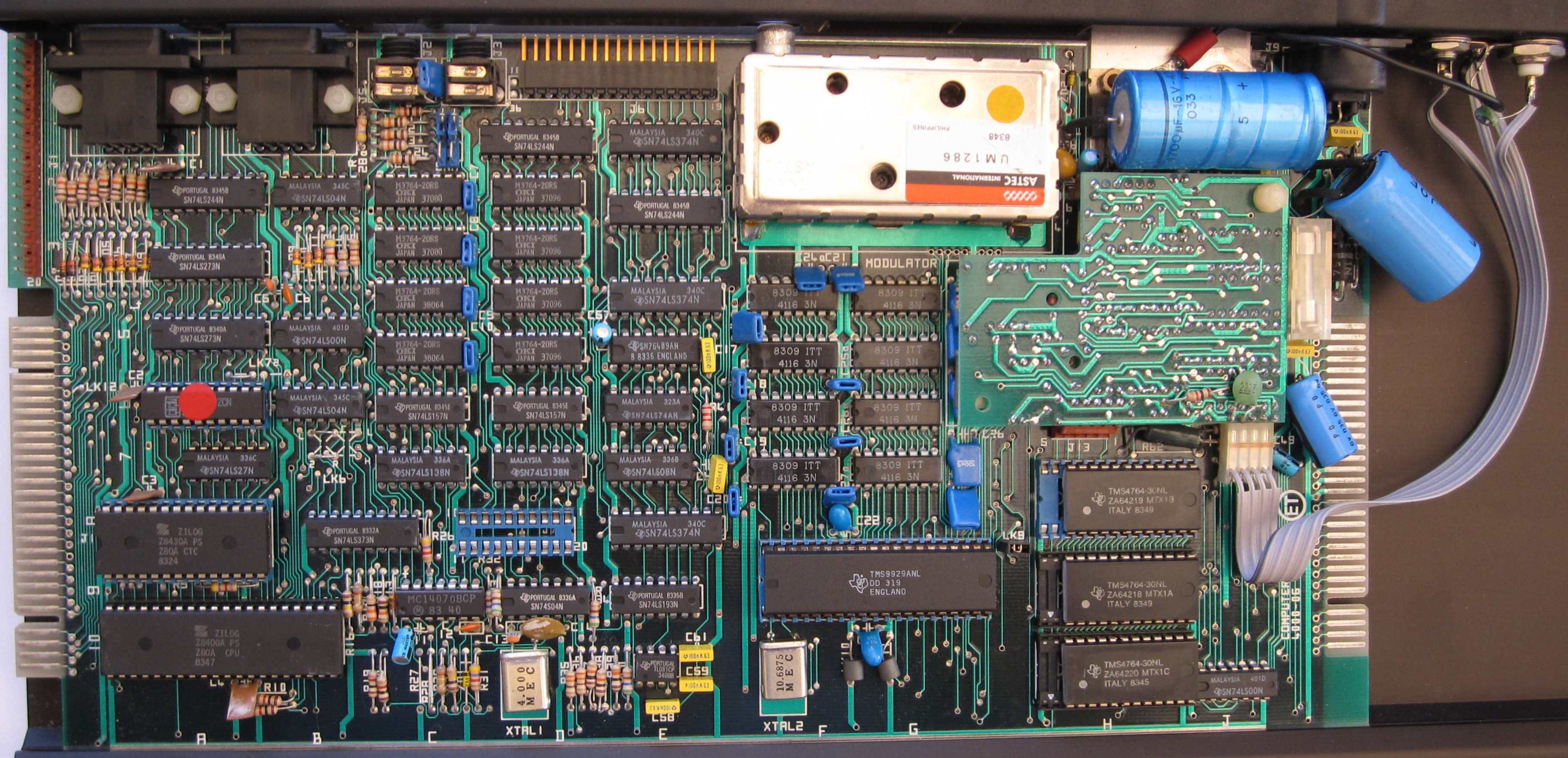
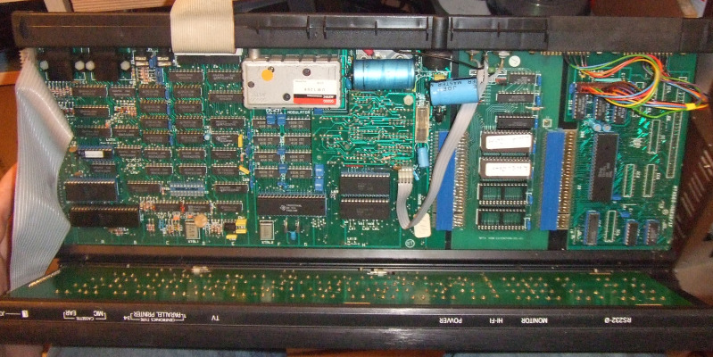
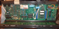
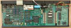
| This photo shows an unexpanded MTX512 with a
4000-05 version computer board. Optional internal
expansion boards, such as memory expansion or the
RS232 board, are attached to the edge connector at
the right hand side of the board. |
 |
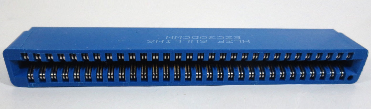
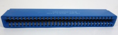
| The expansion connector was designed to mate
with push-fit connectors like this one.
Unfortunately, the "finger" contacts on the board
and the connectors used were of low quality and
prone to problems. |
 |
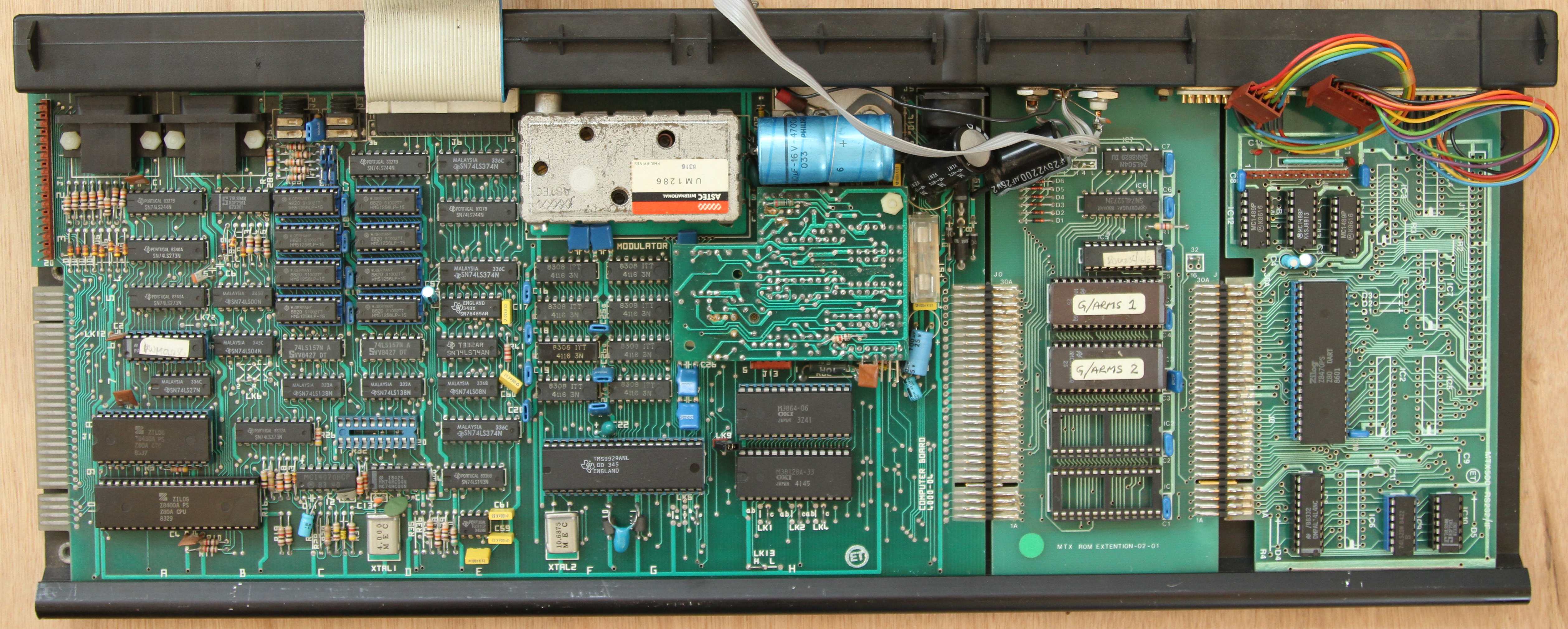
| This photo shows the internals of an MTX512S2
supplied as part of a
Video
Wall System, it has a Video Wall ROM board and
an RS232 board (without the FDX interface
components) fitted, using push-fit connectors to
attach to the exposed edge connector shown above.
(Photo courtesy of Mike Rudkin) |
 |
| If expansion boards have been fitted
after market, then they are almost certainly going
to be of the push-fit type, allowing the boards to
be easily removed. However, because of the
problems with the edge connectors, Memotech resorted
to soldering the connectors of factory fitted boards
to the adjacent board as shown on my Video Wall
photo. If your expansion cards were factory fitted,
then they may also be soldered and difficult to
remove. |
| This photo shows the internals of an MTX512S2
supplied as part of my
Video
Wall System, it also has a Video Wall ROM board
and an RS232 board fitted, but, with the edge
connectors soldered, meaning that the boards more
secure, but making removal difficult. |
 |
| Provided that the
connector has not been soldered, the option board
can be separated from the computer board and slid
out of the right hand side of the case. |
|
MTX Internal Expansion Boards |
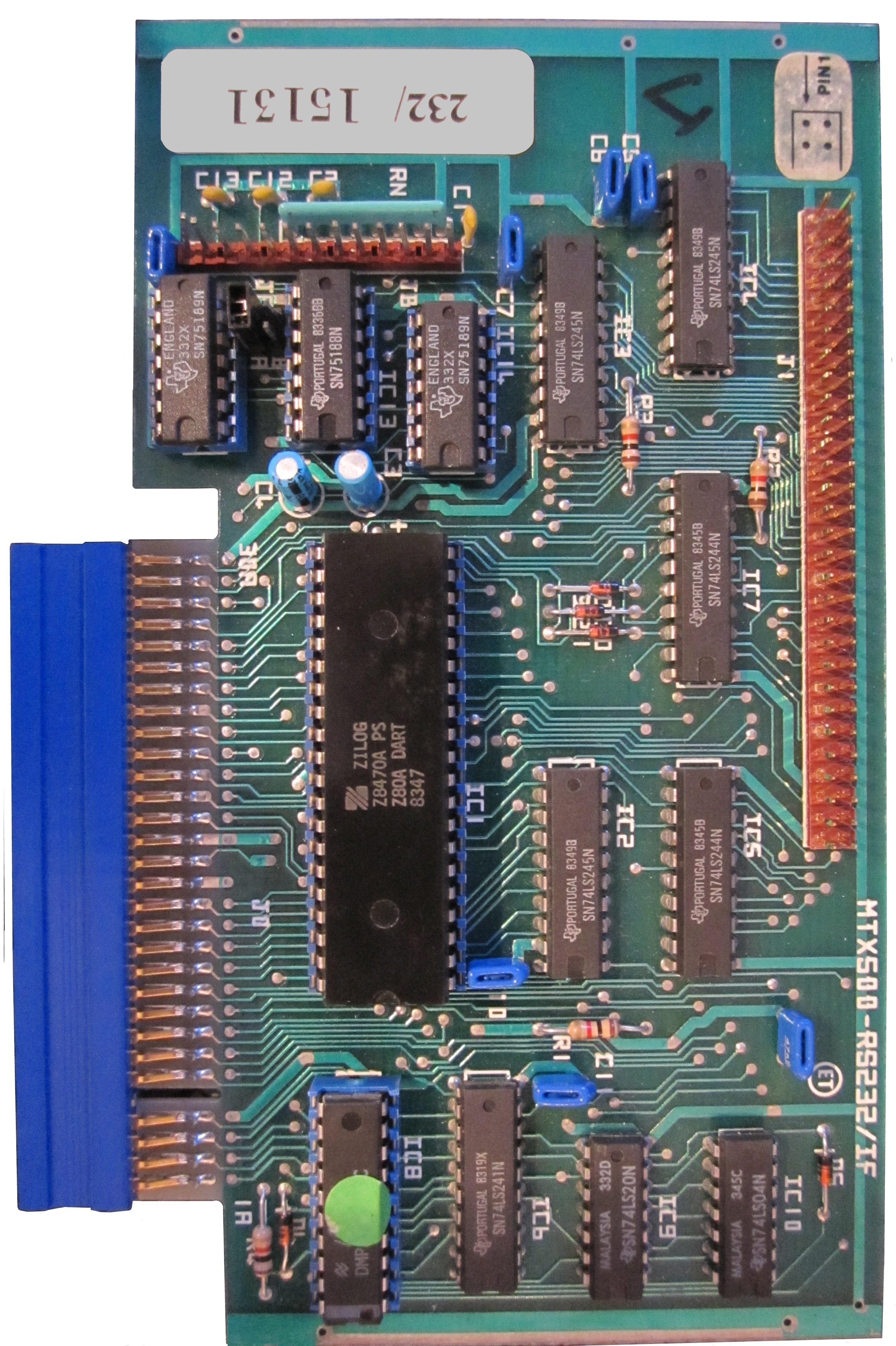
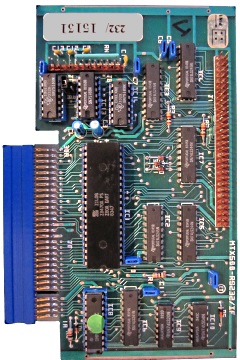
| Combined twin port RS232 and FDX Interface
Board When fully populated, this board
provides two RS232 compatible serial ports and a bus
interface for the FDX disk system.
The short header at the top of the board is for
connection of the RS232 ports to the MTX 25 way "D"
connectors. The header on the right is the connector
for the 60 way ribbon cable to the FDX.
The board was also shipped with the components
for only one or the other of the two interfaces
installed. |
 |
| Memory Expansion Board |
photo coming soon . . . |
| |
|
| |
|
| |
|