|
 |
The Memotech MTX Series |
 |
Memotech Compact Flash System - Version 2
CFX - II
one ?)
Introduction
CFX-II is a
development of CFX, which itself
was spin-off of the Compact Flash storage system developed for
MTXPlus+, our modern day,
fully compatible, MTX "super computer". For full details of the
development and features of CFX, see the
CFX project page.
CFX-II started
life as SFX, see the now redundant
SFX page for the background. As the design progressed, it became clear
that we were really working on an enhanced CFX, rather than a
completely new idea, so the SFX name was dropped and we decided
to rebadge the new design as CFX-II.
Changes from CFX Version 1
The Compact Flash interface in MTXPlus+
and CFX uses two of the 8-bit ports of an 82C55 PPI to
facilitate 16 bit access to the IDE interface. As well as
supporting Compact Flash cards, this interface would
theoretically also allow hard drives or optical drives to be
used, however, the use of those types of devices is unlikely to
have any practical use on a 4MHz MTX.
It is possible to use the Compact Flash
in 8 bit mode which does not require the 82C55, Martin did some
testing in 8-bit mode and found that the data transfer rate was
actually about twice as fast as 16 bit mode. We decided to use 8-bit mode
for CFX-II which would be faster than
CFX and reduce the component
footprint, at the expense of 16 bit compatibility.
While SFX was still at the concept stage,
a couple of other enhancements were added. Martin and I had been
discussing the non-Memotech Silicon Disk that was present in one of my FDXs
and decided that adding a Silicon Disk to SFX was feasible. In
addition, during
Memofest 2016, Bill Brendling had demonstrated an
80 Column card add on for CFX
based on the
Parallax Propeller. Bill's 80 column modification has been
added to CFX-II.
NB: the 80
column mode is only available under
CP/M; the MTX TV and video (AV) outputs are still used to
display the 40 column output from the TI 9929 VDP in the same
way that the Memotech 80 column card was used in the CP/M
version of FDX and SDX.
One of the limitations of using
CFX on a 32k MTX500 was the inability to run
CP/M, as the operating system needs 64k of RAM. This was also
the case with Memotech's SDX and FDX disk systems which only ran
on MTX512 and above computers. Since it was relatively
straightforward to add a 32k "skinny" DIP RAM to the
CFX-II board, this change was also included.
As with CFX,
CFX-II is self
contained - it does not require any modifications to the MTX
motherboard ROMs.
Hardware
CFX-II comprises of
:
-
An SSTSF010 128 kB x 8 CMOS Flash
holding the CP/M, SDX and support ROM images
-
A 512 kB CMOS SRAM for the Silicon
Disc (optional)
-
A 32kb RAM in a narrow DIP package
for the 32k to 64k MTX memory expansion (optional)
-
A
Parallax Propeller Microcontroller Unit (MCU) for the 80
Column board hardware
-
A serial EPROM storing the executable
code for the Propeller chip
-
A Programmable Logic Device (CPLD)
incorporating all of the glue logic previously done in 74LS
logic
-
JTAG Programming port for the CPLD
-
Programming interface for the serial
EPROM
-
VGA Connector (external version) or
Pin header (internal version) for 80-Column output
I/O Port Range
In Memotech's original design, I/O ports below 20h
can be provided by the motherboard and internal/external
add-ons. Ports 20 and above were to be provided from within the
FDX, the SDX ROM used ports 10h to 14h.
As with MAGROM, I wanted the flexibility to be able to mount
CFX internally, thus board space is at a premium. In Version 1
of CFX, the glue logic was done using 74 series components and
with the small
number of logic gates that it was possible to fit into the footprint, the range of I/O decode lines
was very limited, so Version 1
used Z80 I/O ports 6Ch to 6Fh. This port range was not used by Memotech and is shown as available on Andy Key's list of I/O
ports used by Memotech and for modern day add-ons1.
In Version 2 of CFX,
the glue logic is done in an Altera MAX7000
CPLD, although all of the address lines are connected to the
CPLD and the full range of Z80 I/O ports could be decoded, the
I/O port range has been maintained for compatibility reasons.
Since the emulation of the 80 column card
is done using different display hardware than Memotech used in
the FDX/SDX display controllers (Motorola
6845) and the ROM needed to be changed to support the new
hardware, there was no advantage in retaining the original 80
column card I/O port assignments () so ports 60h and
61h are used to interface with the Parallax
Propeller.
PCB Dimensions
As well as the depth constraint, there is also a limit to the
width of an internal board if it is to be compatible with the
existing range of MTX expansion boards, RAM, ROM, and the
RS-232/FDX interface board (using only the RS232 ports).
Each of these boards was half the width
of the expansion card area, i.e., up to two expansion
cards could be installed internally. (A combined
80-column/RS-232 board, taking up the full width of the
expansion card area was released later but is not
relevant to this discussion, since it was meant to
support Memotech's own disk based CP/M add-on using a
disk interface connected the the cartridge port on the
left hand side of the case. If you have one of those,
you probably don't need CFX-II.
The Version 1
CFX PCB was narrow enough that edge
connectors could be installed on both sides of the board
and it could be switched between internal and external
mounting at will - even if a Memotech memory board was
installed. With the increased component footprint of
CFX-II, this would no longer have been possible. If a
Memotech memory board is installed, the CFX-II PCB could
not have had the right hand side edge connector fitted
without removing the MTX computer side plate. In most
cases, this is not likely to be a problem as the Memotech memory board could be removed. It would only be
a problem if the Memotech memory board could not be
removed if it were soldered in. |
The other space constraint on
the CFX PCB was driven by the price points set by the PCB
manufacturers that I use in China. There is a price break at
100mm x 100mm and the cost of CFX is minimised if I keep the
PCB size below this limit. Meeting this target with the
increased complexity of CFX-II proved to be a real
challenge, both to my component layout "skills" and the
track auto-router that I use. The only way that I could keep
to this PCB size limit was to remove the second edge
connector, meaning that the standard fit for CFX-II will be
external only. However, based on
the problem that I accidentally introduced with
Version 1.1 of the MAGROM
PCB and the convenient solution suggested by Martin,
this isn't actually a barrier to installing the PCB
internally. Although the board would not be reversible,
depending on how the edge connector is fitted to the PCB,
the board can be installed either externally or internally.
Firmware
The CFX-II ROM provides versions of both the MTX SDX BASIC ROM
and a CP/M ROM based on the original Memotech CP/M ROM with 80
Column Card support. See the
CFX-II firmware page for full details.
Hardware
|
Hardware |
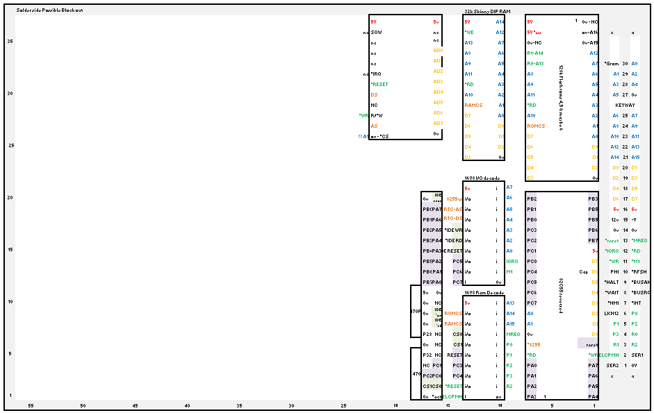
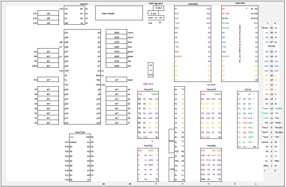
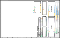
Version 0.3 of the
provisional SFX design, incorporating a 32kB RAM, RTC,
82C55, 2 x GALs for I/O and Memory decode logic and
512kB Flash memory.
The Flash was intended to hold the
SFX System, CP/M and SDX ROMs, with the remaining
480kB originally intended to be used to store MAGROM game
files. |
 |
| Martin's V0.3 prototype
board |
 |
| Solder side of the V0.3
prototype board |
 |
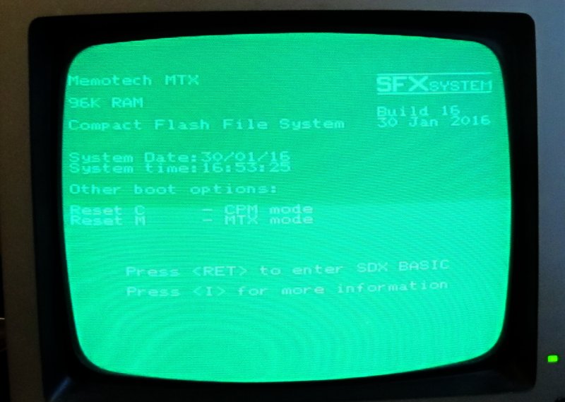
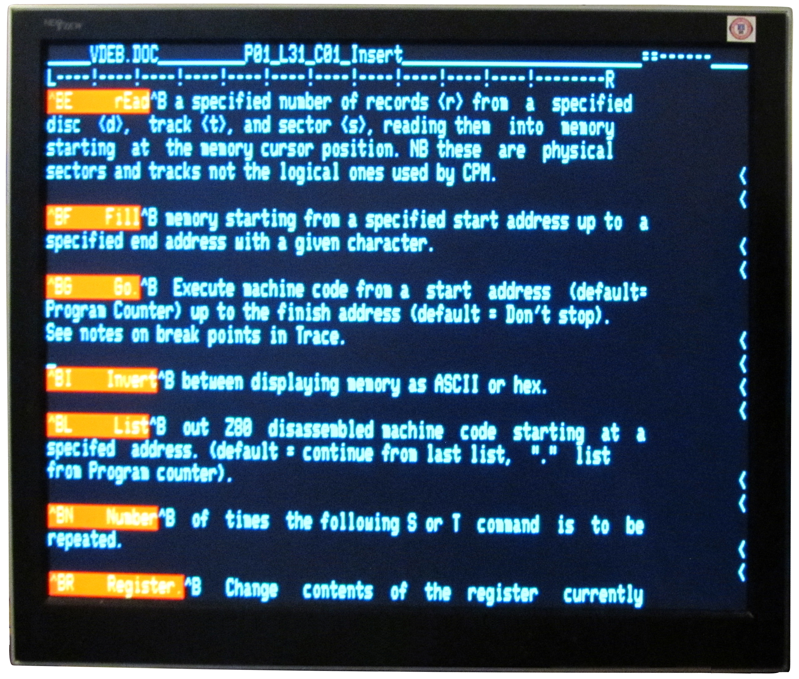
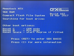
The prototype board running
an early version of the SFX
ROM.
The screen shows the RTC working and the
system seeing the additional 32K of RAM - in this
case, the board in plugged into a 64K MTX, giving
96K total RAM.
This was as far as the
proposed SFX got before Bill showed off his 80
Column card board at
Memofest 2016. |
 |
With Bill's input, the
functionality of the board has now been expanded to
include VGA output from an emulated 80 Column board.
In addition, Silicon Disc functionality has been
added.
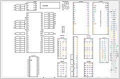
As you can see from Martin's draft
V0.6 layout, the component footprint has increased,
which led us to drop the RTC from the scope of
SFX to save board space. |
 |
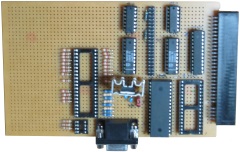
| Martin's partially
completed prototype V0.6 board, now taking up around
70% of a Eurocard size prototype board and does not
include the 32kb RAM addition. |
 |
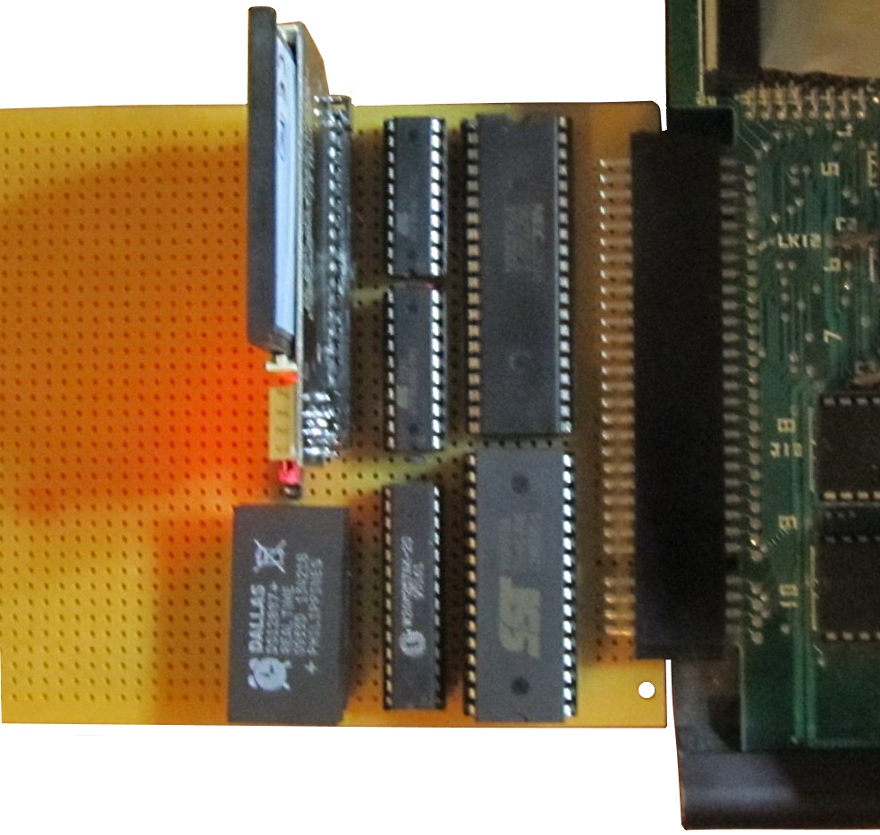
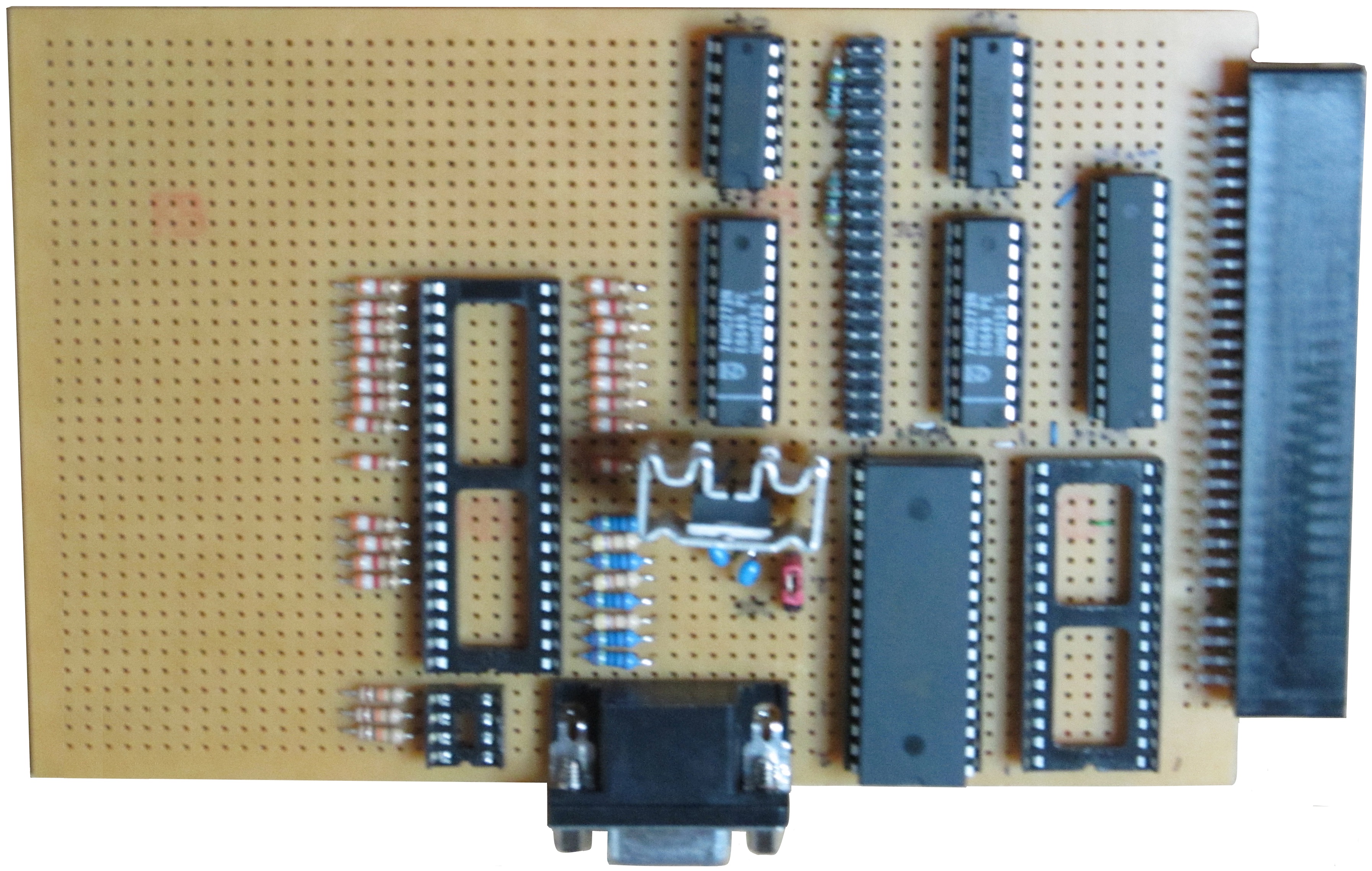
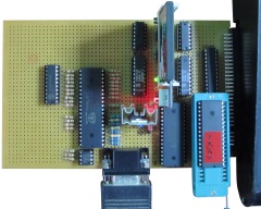
Fully assembled prototype,
powered on and working !
As you can see,
there are significantly more components on the board
than CFX, but I am still
hopeful that the final PCB will be suitable for both
internal and external mounting.
This will
probably mean mounting some components on the
underside of the board so that the portion of the
board in the shallowest part of the MTX case can be
used too. |
 |
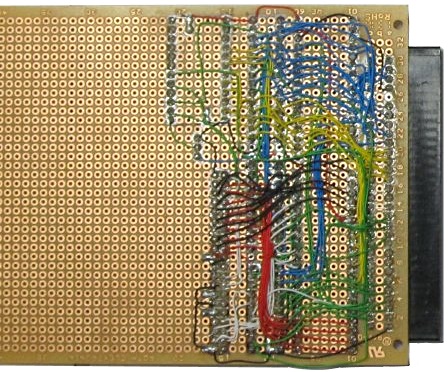
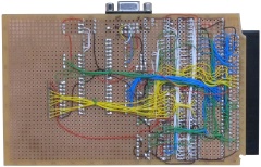
| Solder side of the
prototype board |
 |
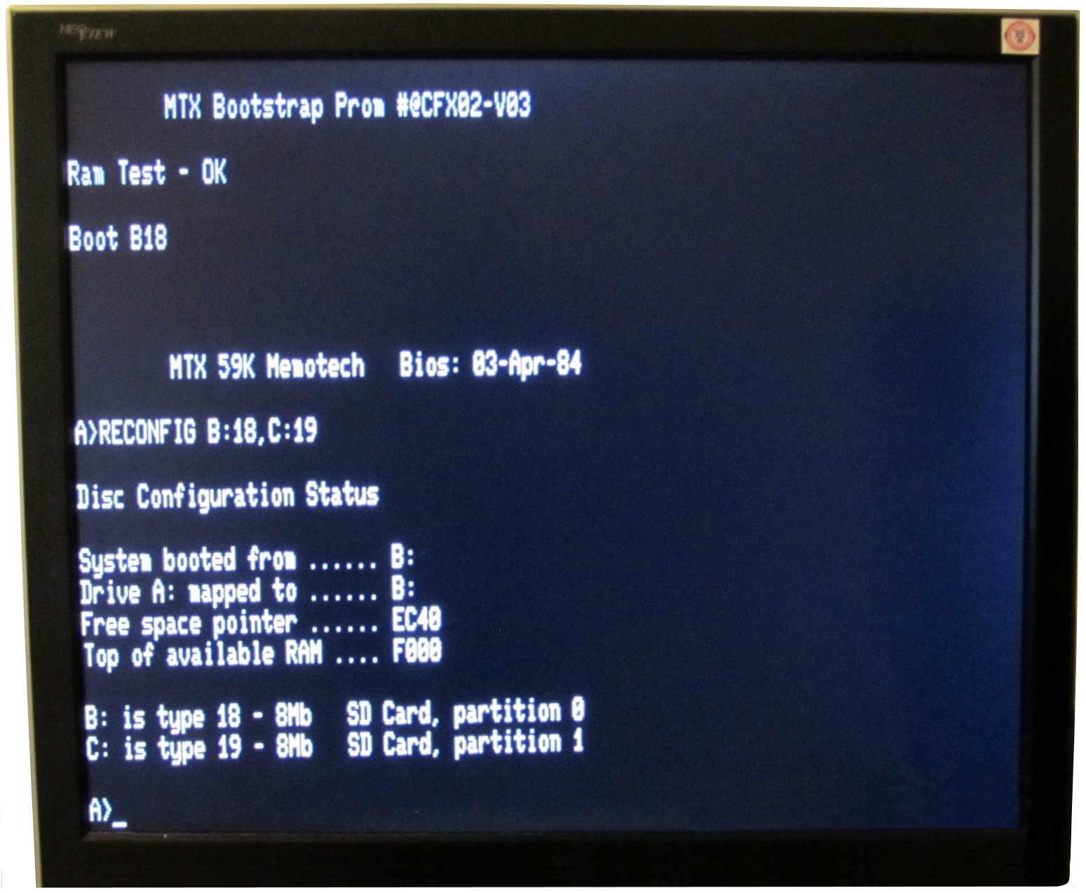
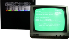
| The output from the
prototype board, showing the boot screen output from
the MTX monitor output and test output from the 80
column screen on a VGA monitor. |
 |
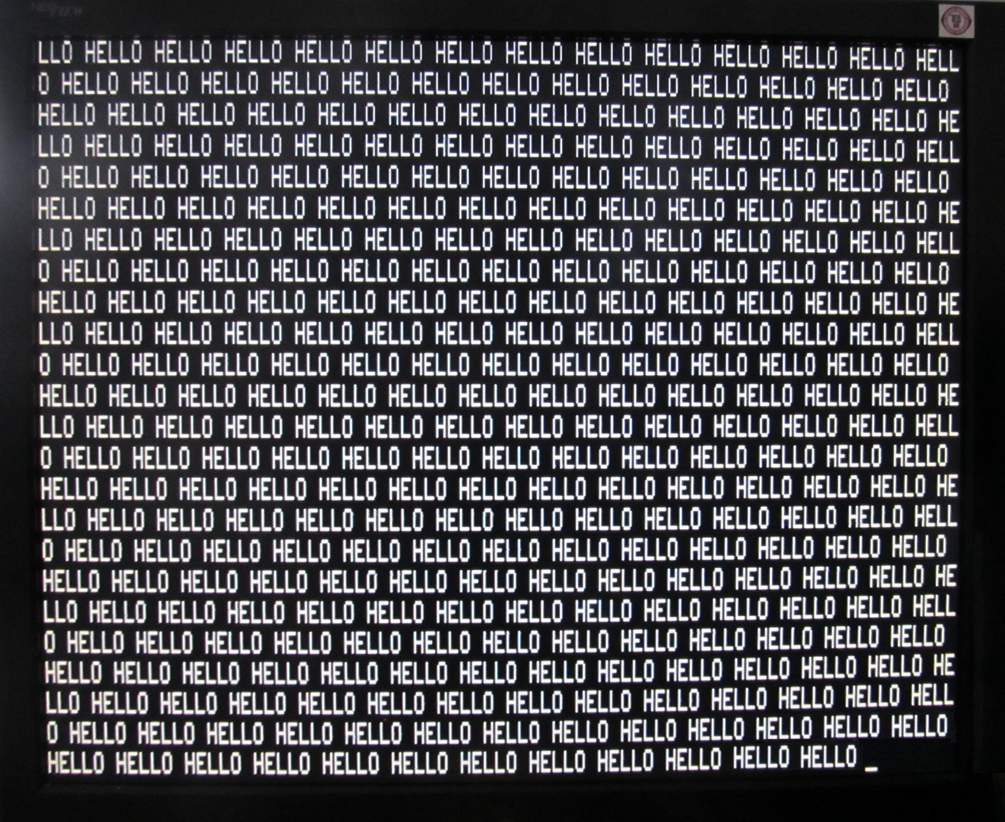
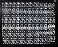
| Close up of the 80 column
output with the screen filled with 80 column text,
displayed on the VGA monitor. |
 |
| Initial test of the 80
Column output under CP/M using the SFX CP/M BIOS and
a very basic driver for the Propeller hardware. |
 |
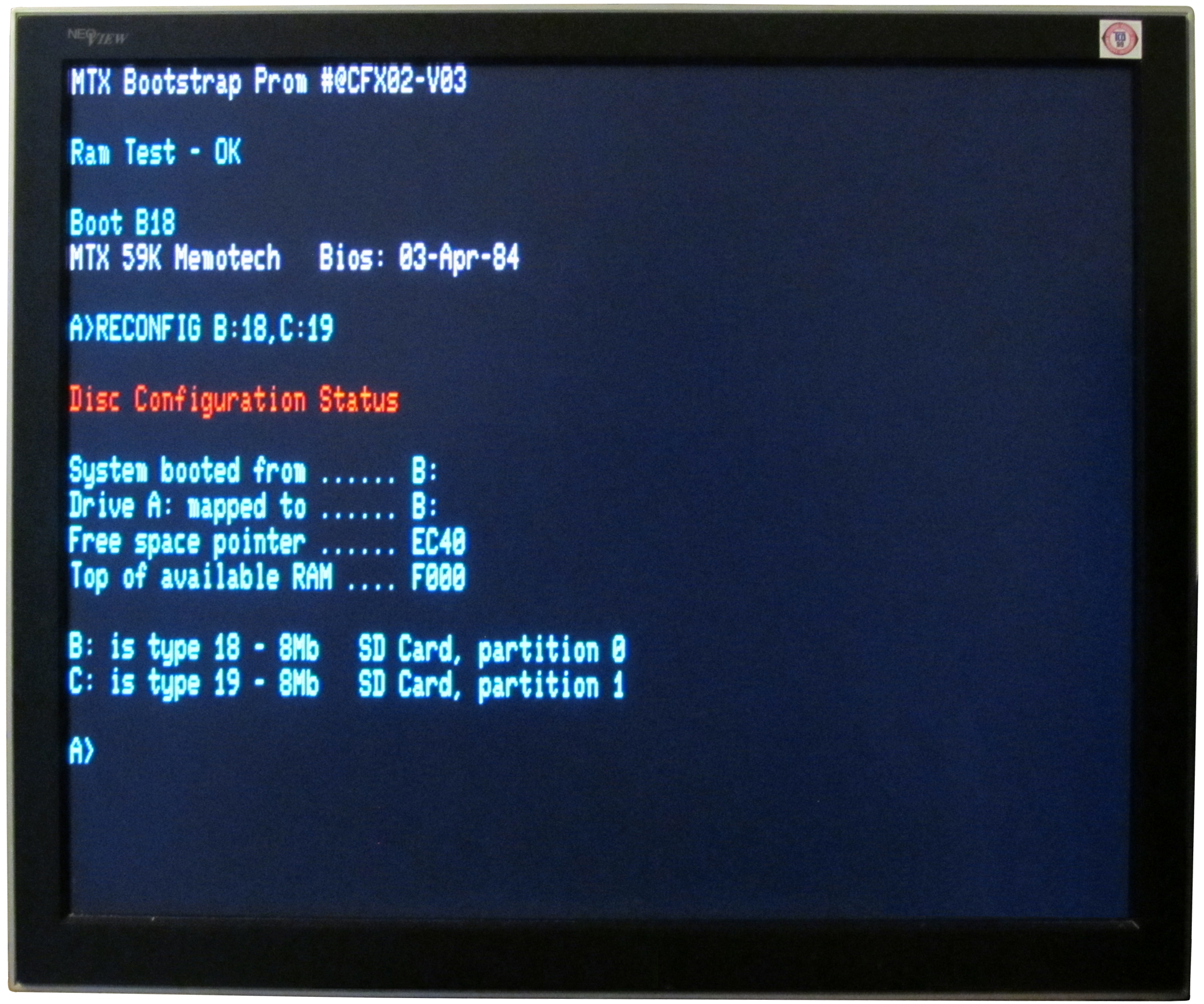
More development of the
CP/M driver - now with colour!
Mimicking the
colour boot screen that would be seen on an FDX with
colour monitor. |
 |
Screenshot showing colour
NewWord running from CP/M.
At this point, the
80 Column Escape codes have not been implemented, so
scrolling does not work, but the screen display
looks good. |
 |
When, thanks to the hard work of
Martin and Bill, CFX-II
got to this stage, I started to think about building
my own prototype, with the addition of the 32kb RAM
expansion and using a CPLD, rather than 74 series
components for the glue logic.
Despite
having had lots more practice, my soldering "skills"
are still not great and the thought of wiring up
another complex prototype board did not really
appeal to me though. When I saw that my PCB
manufacturer had a bit of a sale on and that I could
get a small run of boards made pretty cheaply, I
decided to take a chance and get a few boards made
based on Martin's prototype with a few, hopefully,
low risk modifications added. |
| I took Martin's design and
replaced the 74 series logic components with an
Altera MAX 7000 CPLD and added a 32kb CMOS RAM in a
skinny DIP package to enable the board to provide
the necessary RAM upgrade to allow a MTX 500 to run
CP/M. |
 |
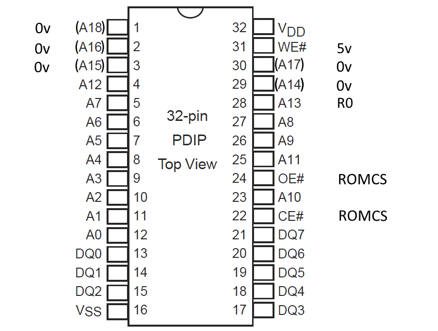
The size of the Memotech
option ROMs was 8kBytes, for CFX we need space for
the SDX and CP/M ROMs, i.e., 16kBytes in two 8kByte
"pages". Address lines A0 to A12
can address 0 to 8191d locations, and A13
allows a second block of 8kB to be addressed. In
CFX, the Page Port R0 line is used to select the
appropriate ROM page.
CFX/CFX-II was designed to use
Flash storage, although only 16kB is used, larger
devices can be used if available. |
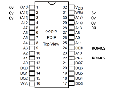 |
CFX/CFX-II can also use EPROMs
provided that it is acceptable for the programming
voltage on Pin 1 to be 0v in normal operation.
A selection of compatible Flash and EPROM
devices are shown in the table - the component
datasheets are available by clicking on the
hyperlinks. |
|
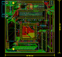
The second edge connector
included in CFX Version 1 was removed to meet the
size constraints described earlier.
CFX
Version 1 had all of the components squeezed into
the top 2/3 of the board to allow the PCB to fit
underneath the MTX keyboard when it was mounted
internally.
The increased component count for
Version 2 means that this is no longer possible but
the PCB should fit internally if mounted upside down
as has been done with the MAGROM Version 1.1 PCB. |
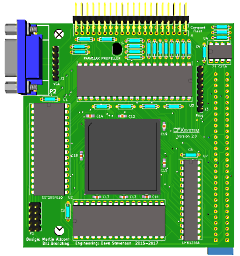
 |
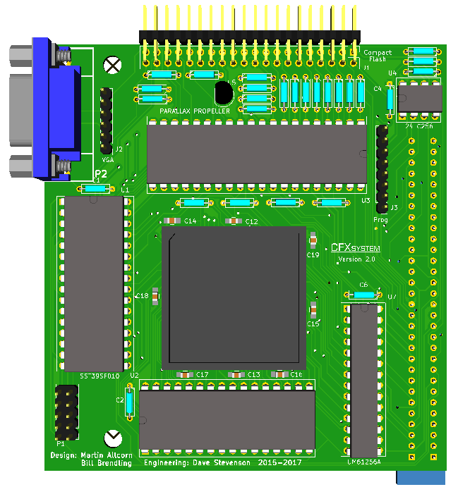
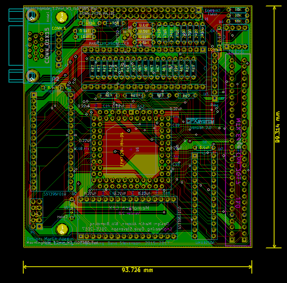
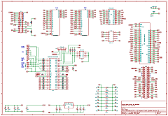
The KiCad 3D view of the
PCB showing how the board would look when configured
for connection to J10, the MTX expansion connector
on the left side of the case.
In this
configuration, the edge connector would be mounted
below the PCB and a standard 15-pin "D" type VGA
socket installed to connect to the monitor.
Pin headers are included for cabled connections for
the VGA monitor, CPLD JTAG connector and a
programming connector for the serial EPROM.
Not shown are the 18 through hole resistors mounted
inside the 40 pin propeller socket. |
 |
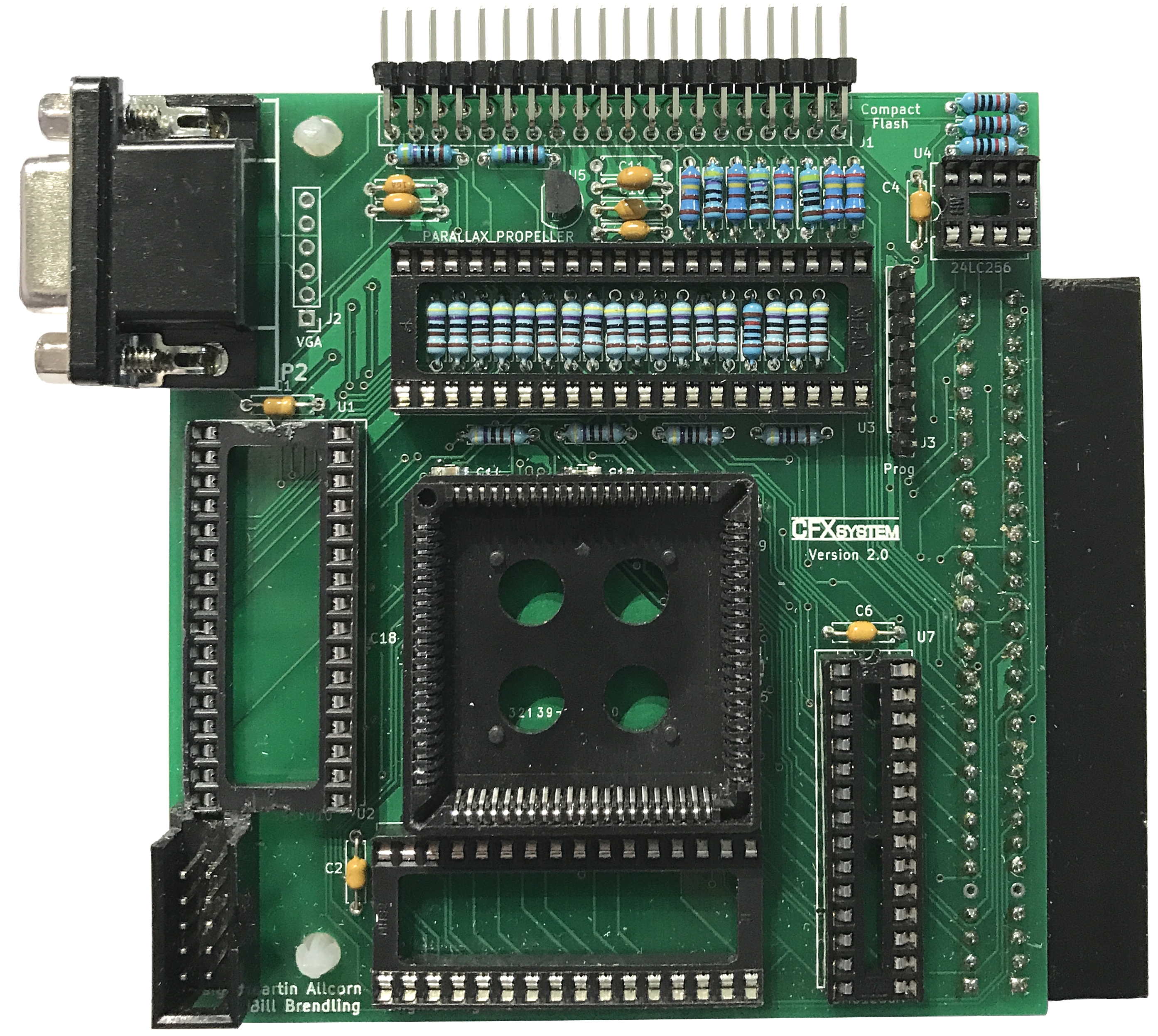
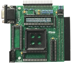
Prototype PCB, assembled
for external installation
There are a few
minor issues with the PCB that need to be corrected |
 |
- The CPLD socket footprint that I used turns
out to be slightly smaller than the sockets that
I have, so there is not enough clearance between
the SMD capacitors and the edges of the socket.
The components can all be fitted, provided that
the capacitors are fitted first, but the socket
then does not quite sit flush on the PCB, but
there's no real problem.
- Using a box type header for the JTAG
connector leads to a clash with the ROM chip.
- VGA connectors for PCB mounting come in
different sizes, while the socket that I have
fits onto the PCB, the ones that Martin have
don't. On the next version of the PCB, I will
see if I can create a more universal VGA
connector mounting
- VCC for the Serial EPROM should be connected
to 3.3V, rather than 5V.
|
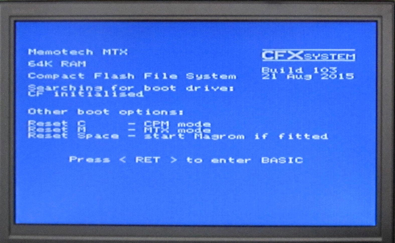
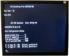
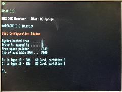
Startup of the CFX-II PCB
with the minimum hardware configuration, i.e., only
the CPLD and system ROM installed.
There was
no CF drive connected and the additional RAM and 80
column video were not installed at this point.
As you can see, Martin has done a nice new
"CFX-II" logo |
 |
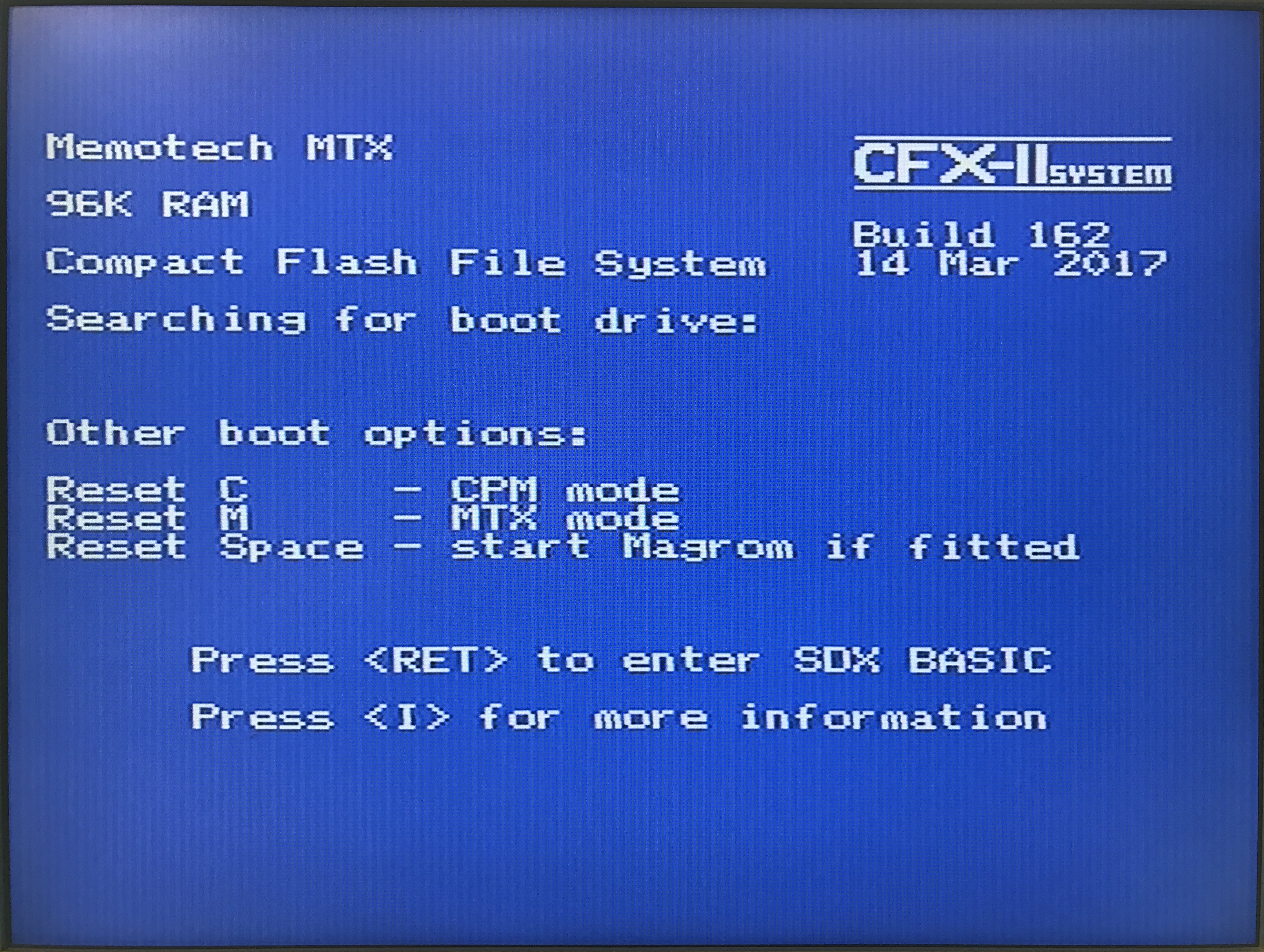
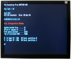
For this test, the
32k RAM has been installed and temporarily remapped
above the 64k RAM area to make it visible when the
board was installed in my MTX512 test bed.
The system correctly reports a total of 96k of RAM
present.
For "production" boards, there is no
real use for RAM above 64k, so CFX-II boards
intended for installation in a MTX512 will likely
omit the 32k RAM chip. |
 |
The next step should just have been
to install the CF card reader and test booting CP/M
and reading/writing the CF card from CP/M and SDX
BASIC, however, things didn't go quite as smoothly
as expected. In fact, were looking pretty ropey for
a while !
The first time that I tried the CF
card, the system booted successfully and things
appeared to be working as expected - unfortunately,
that wasn't to last . . . .
I found that
access to the CF card was unreliable and the CF
drive was pretty much unusable. I tried a number of
things, including using different MTXs, power
supplies, CF readers and CF cards - all to no avail.
I suspected that the power being drawn by the new
design might have been an issue and measured the 5V
current consumption of the bare MTXs, as well as
with CFX-I, CFX-II and REMEMOrizer boards fitted.
The largest power requirement was with REMEMOrizer
(which worked perfectly), but the difference between
all four scenarios was trivial and I ruled out it
being a power issue.
To try and eliminate
construction errors, I even resorted to assembling
another CFX-II, this time for internal mounting, but
the results were the same. At this point, I resorted
to running remote diagnostics - meaning that I sent
one of the assembled boards off to Martin for him to
test on his systems and see whether he could spot
any construction errors that I might have made.
When Martin tried the board, it worked perfectly
on both of his MTXs. At this point the differences
between our MTXs came to light. My machines have the
original NMOS Z80 CPUs installed, whereas Martin had
previously replaced the CPUs on his machine with
CMOS chips. When this information came to light, I
replaced the CPU in my machine with a CMOS Z80 and
lo and behold, my internal CFX-II now worked without
error.
The original CFX design included a
82C55 PPI that was used to interface the CF reader
with the Z80 CPU and support 16 bit transfers.
CFX-II uses 8 bit data transfers and the 82C55 is no
longer needed. This means that the Z80 is directly
interfaced to the CF reader, which is obviously an
issue with an NMOS CPU.
It would likely be
possible to put buffers between the CF card and the
Z80 control and data lines, but this would mean
increasing the PCB size. Instead, I will probably
include a replacement (CMOS) CPU with CFX-II
purchases.
|
Ta Da!
With a CMOS
CPU installed in the MTX, the system can use the CF
reader reliably.
This version of the ROM uses
the SCPM 62 column graphics mode for CP/M as was
used for CFX Version 1.
|
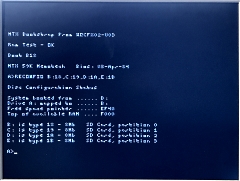 |
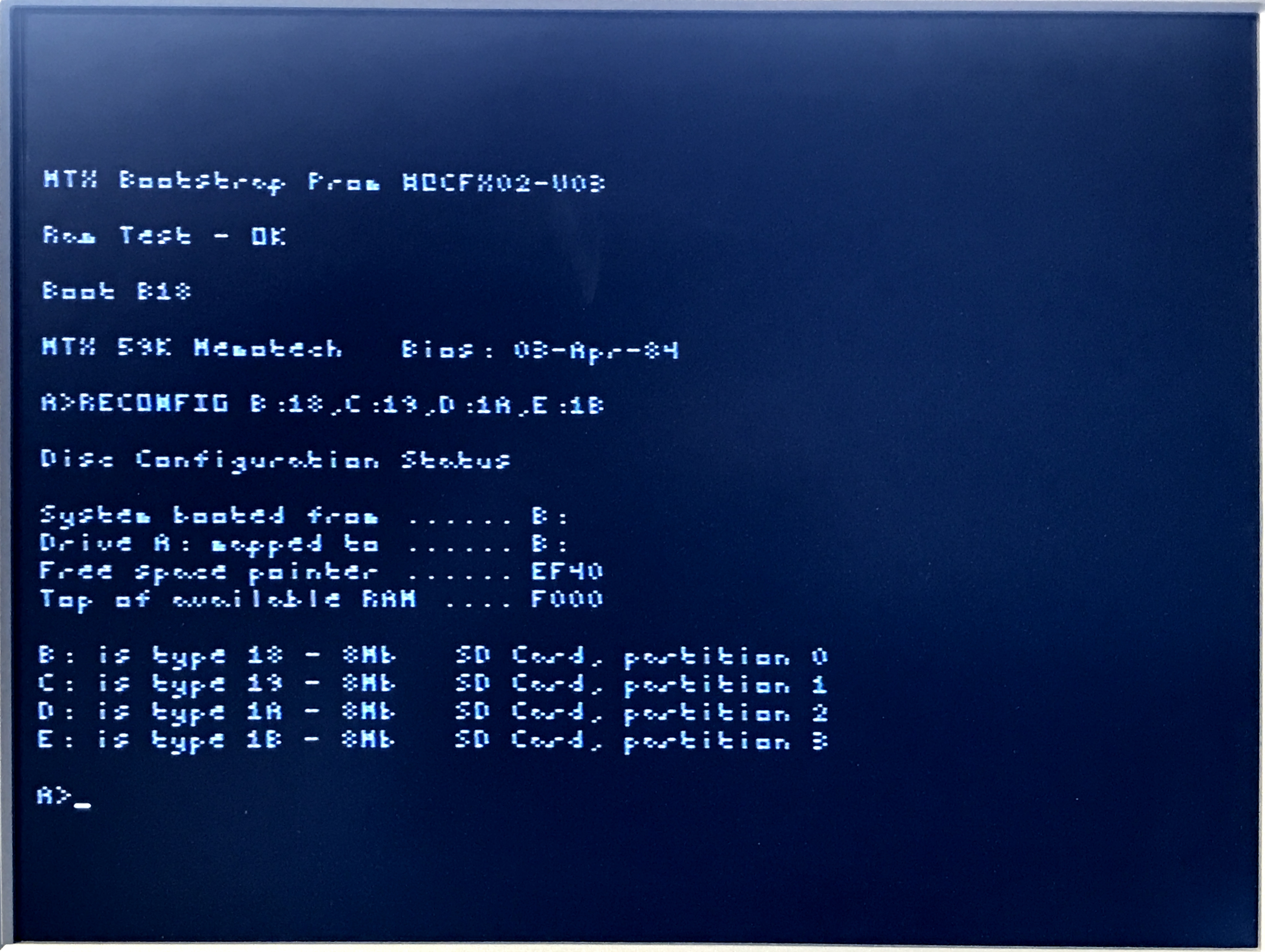
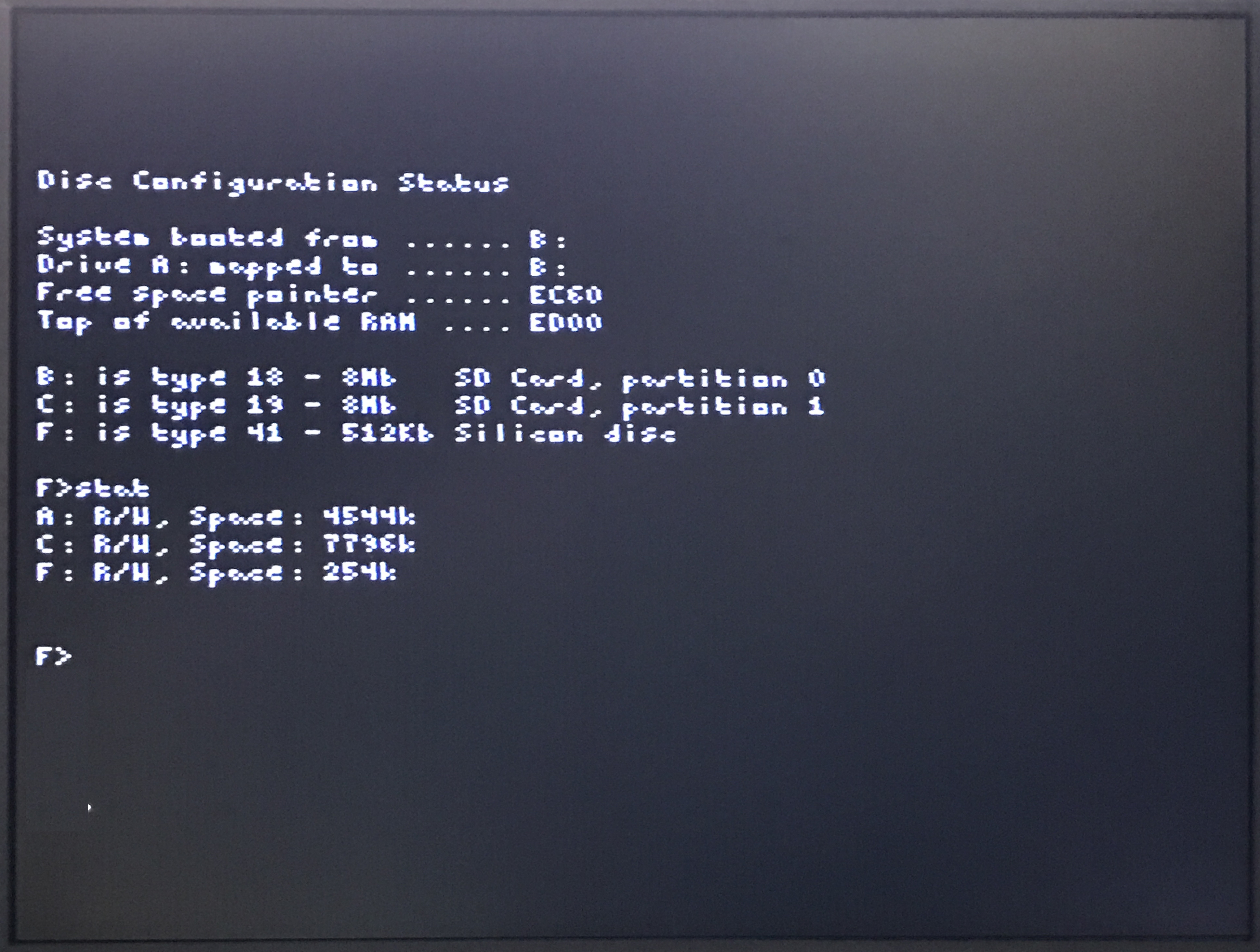
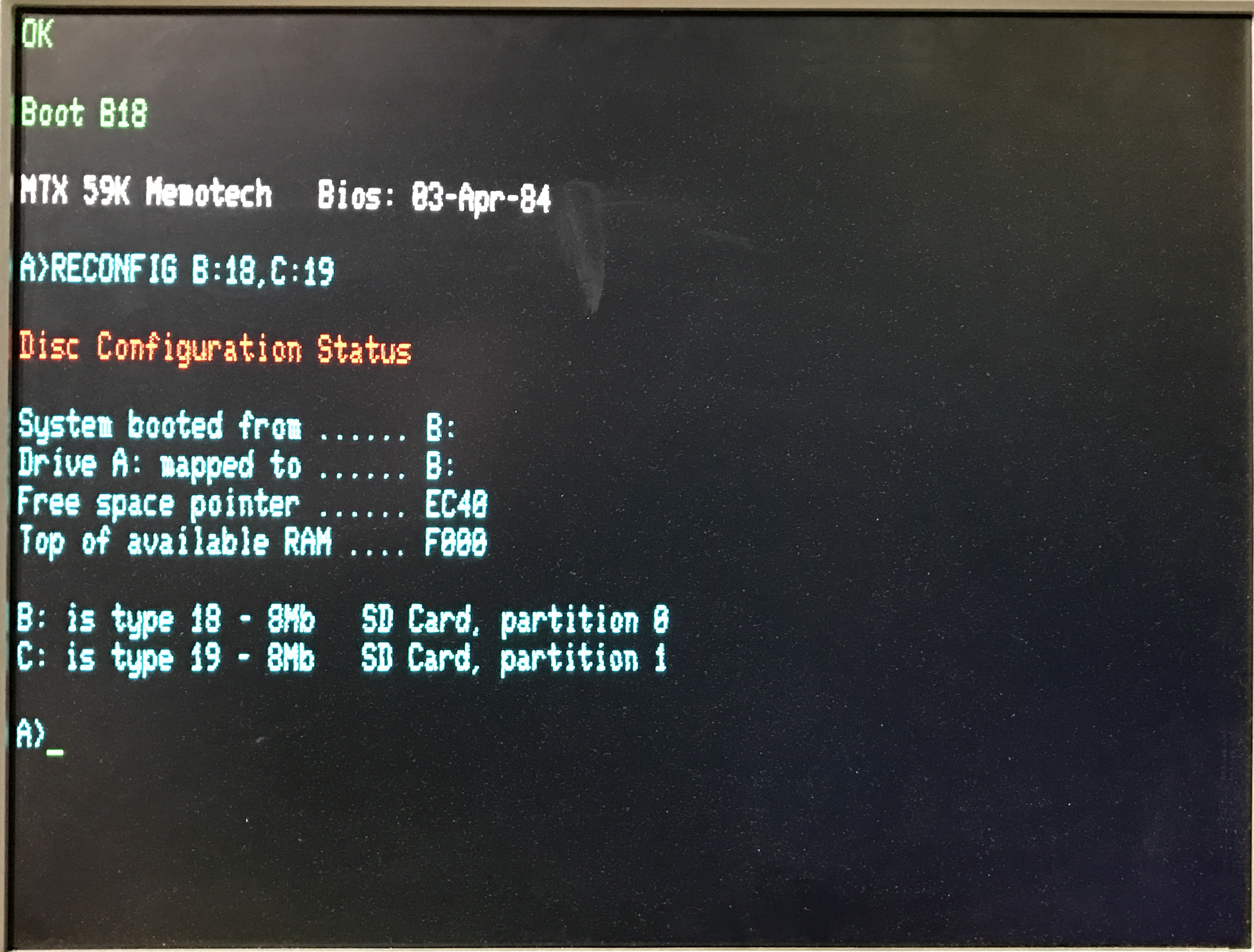
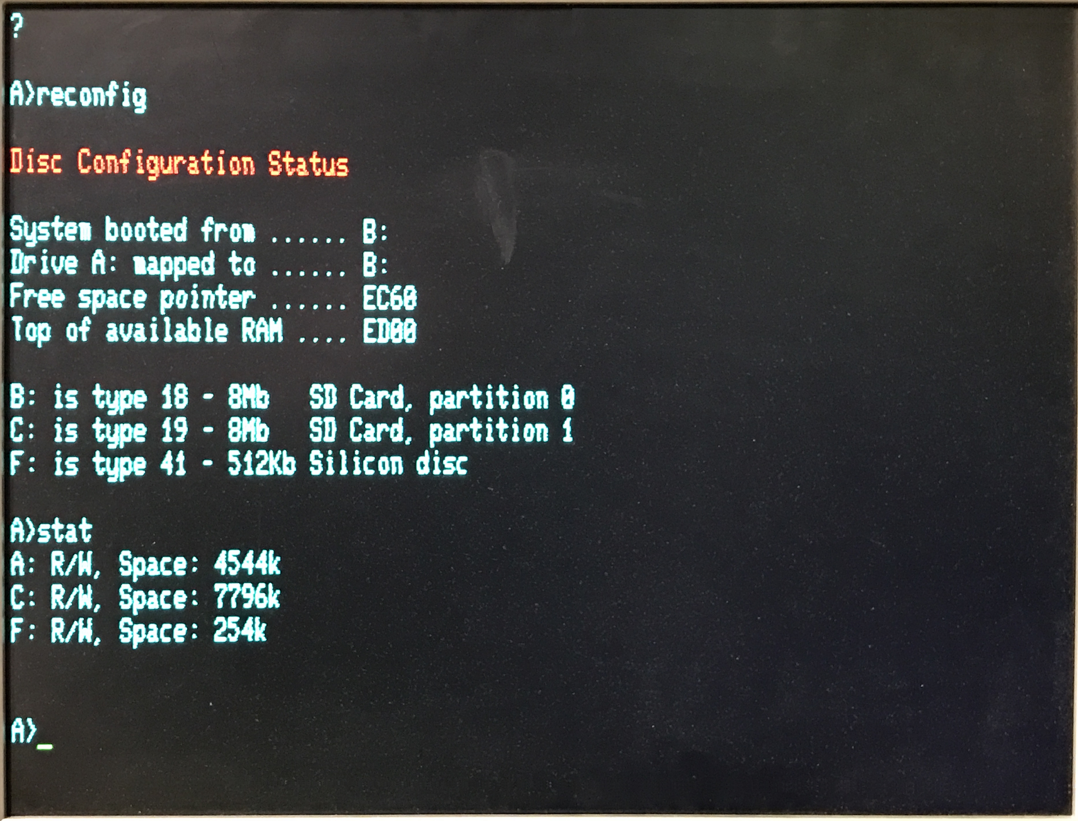
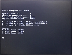
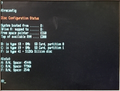
With the 512k SRAM
installed, the system can be configured to have a
type 41, 512k Silicon disc as shown here.
Although the Silicon disc contents survive reboots,
the disc handler must be reloaded and the drive
reconfigured after a reboot. This will be fixed with
a ROM update.
(Update : This was fixed in ROM
Version 206) |
 |
| And finally, with the ROM
updated to drive the emulated 80 column card
hardware and the Parallax Propeller and its boot
EPROM installed, you can see the significant
improvement in the quality of the CP/M output when
driving a VGA monitor. |
 |
| And the colour VGA output
after the RAM disk has been configured. |
 |
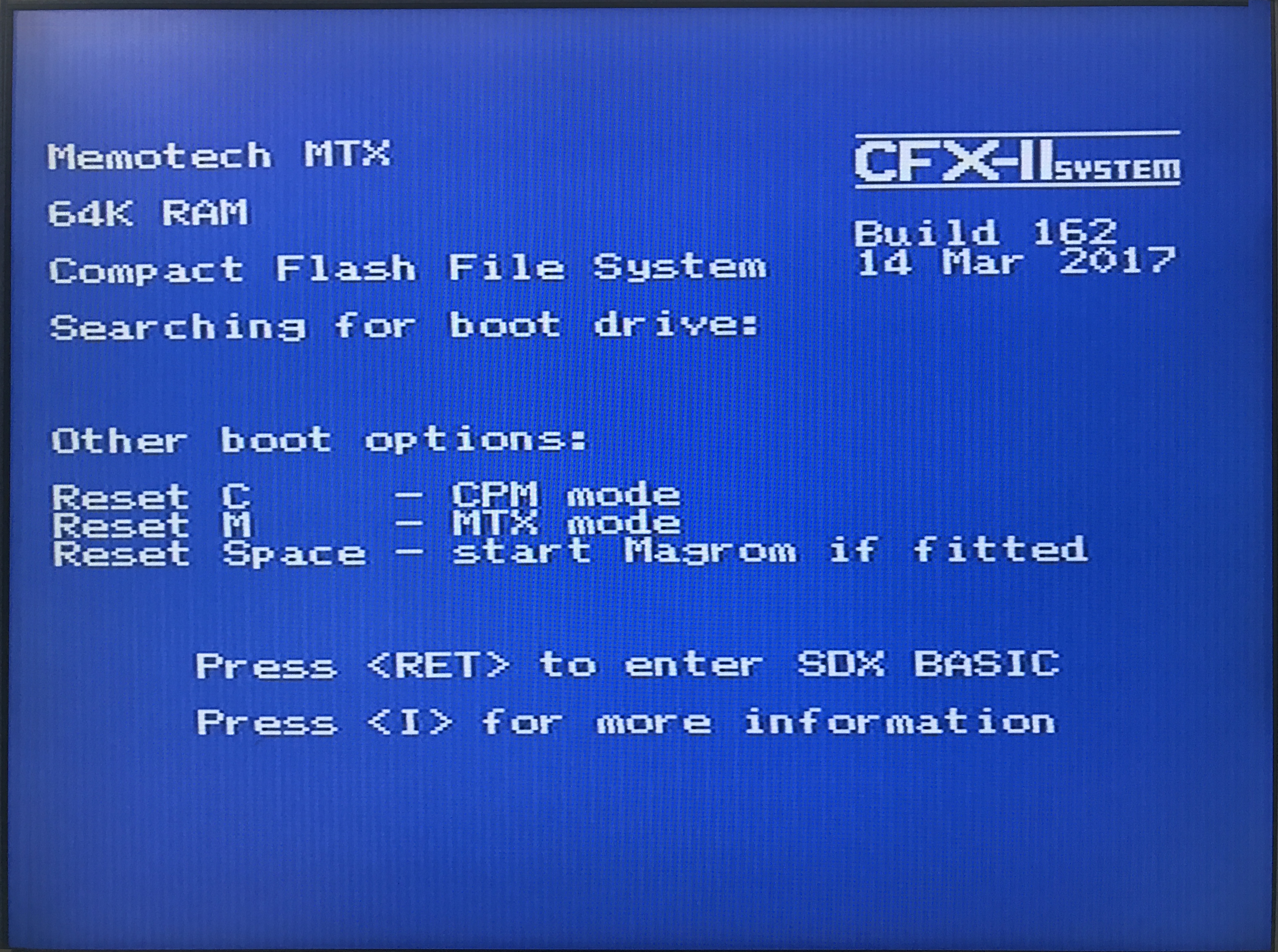
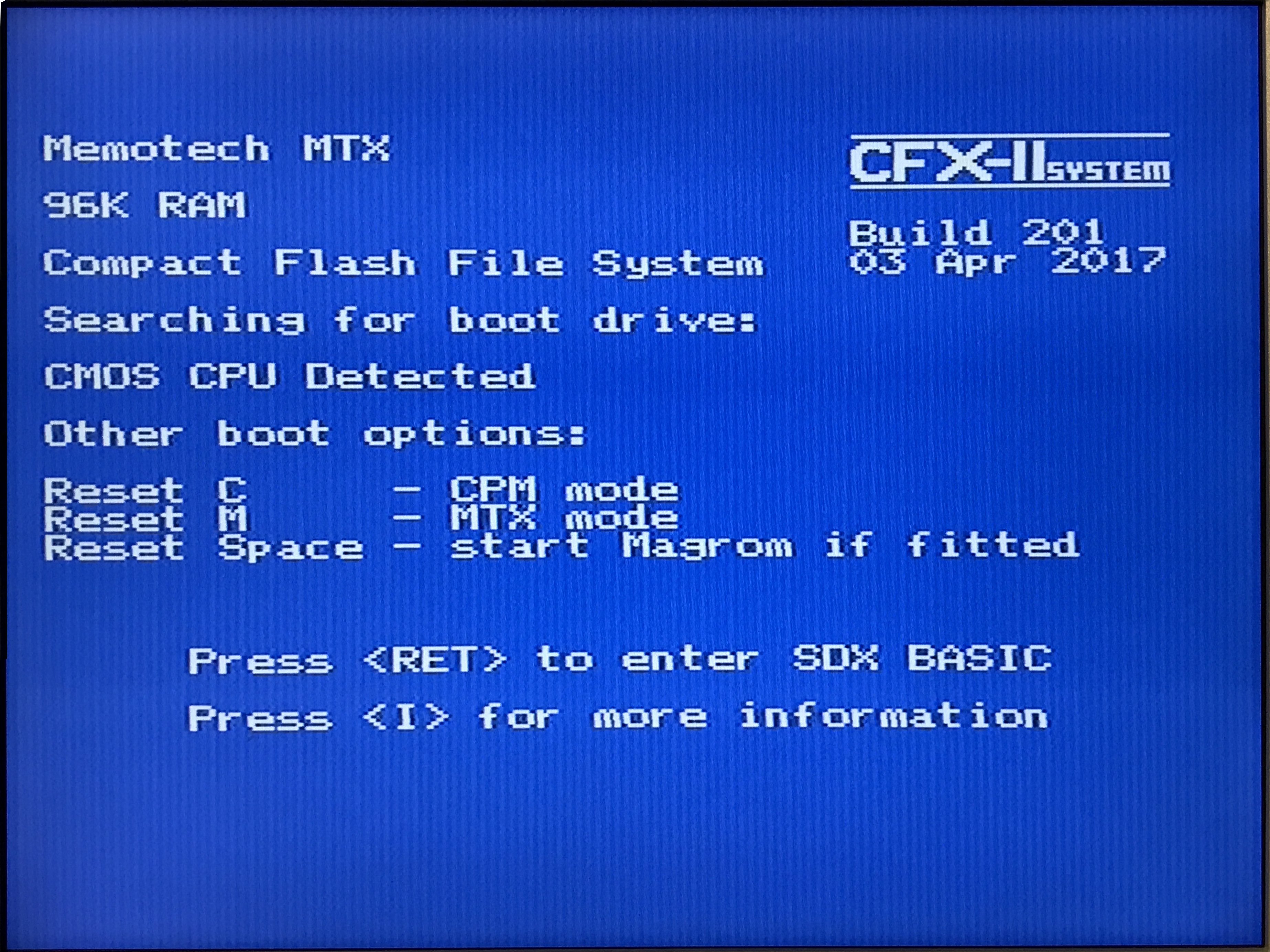
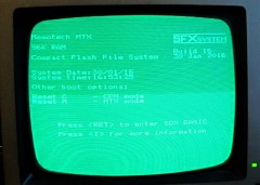
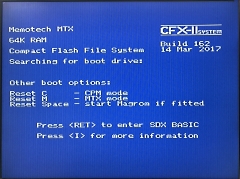
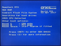
To differentiate the CFX-II
builds from CFX, Martin has increased the Build
number to 2xx.
As CFX-II will need the MTX to
have a CMOS Z80 CPU installed, the boot screen now
reports the CPU type as either CMOS or NMOS and
issues a warning if an NMOS is found. |
 |
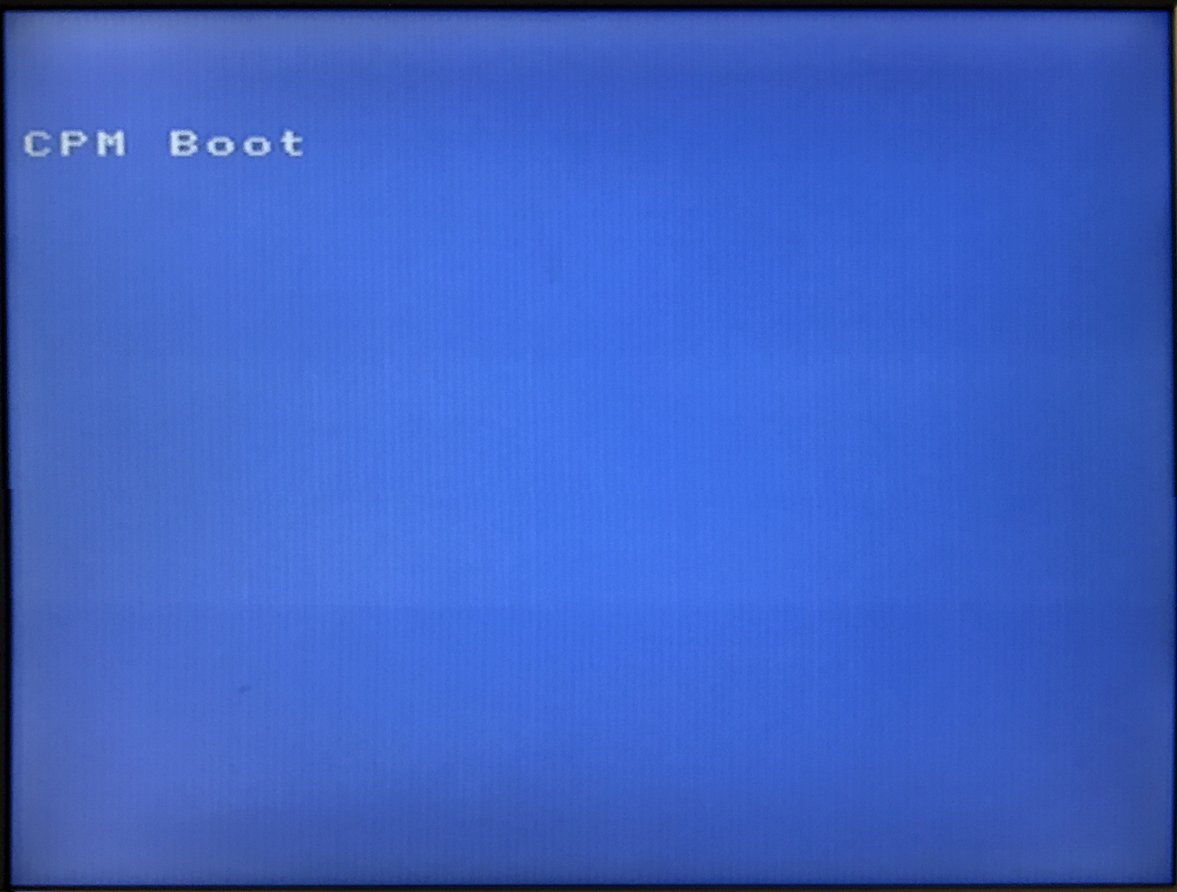
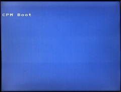
| If CFX-II is booted into
CP/M mode (with <reset> <c>), the MTX VDP output
displays "CPM Boot", rather than displaying a
blank/black screen as the original MTX FDX and SDX
add-ons did. |
 |
Pushing the envelope
- or rather, pushing the Parallax Propeller (too
far)
As described above, the basis of design
for CFX-II was for the Parallax Propeller to
generate an 80 column VGA output from an emulated 80
column card but not to generate video from the VDP -
in the same way that the FDX/SDX 80 column cards
were independent of the VDP output.
Tony
Brewer suggested that Bill might be able to also use
the Propeller to generate a shadow display for the
VDP, allowing the VGA screen to also display output
from games etc. Bill did think that this was going
to be a stretch for the Propeller; whilst it is a
nice device, it is not particularly powerful,
particularly when compared with some other
microcontrollers, but he has had a good stab at it!
|
| |
|
Status
As
of the end of March 2017, three working CFX-II
PCBs have been assembled and proved working, one internal
and two external. These three boards have proved that
CFX-II meets the original design
intent, they have working 80 column VGA output, Compact
Flash "disk drive", 512k Silicon Disc drive and 32k memory
expansion available, when used in an MTX with a
CMOS CPU. The minor PCB layout issues
described above are not essential for CFX-II
to work and would not have prevented me from supplying the
device to anyone interested - that is still the case - see
below for availability.
However, when the requirement to fit a CMOS CPU as part of
the CFX-II upgrade became clear,
we started to plan a redesign to allow CFX-II
to work without replacing the original MTX NMOS CPU.
Although in itself, this should not have necessitated large
scale changes, a number of other changes are being planned
that will likely delay shipping of what will become
CFX-III for at least 2-3 months, if
indeed, it actually sees the light of day!
Availability
I shall shortly be taking orders for CFX-II,
please send me an e-mail if you are interested in buying
one. The price is
£tbc, including Postage & Packing to
the UK, plus
any applicable payment fees, e.g., Paypal (unless you pay
the fee).
News Flash : 02 April 2017
Due to the pending redesign, I plan on offering the few
CFX-II boards that I will have available (<10) to "early
adopters" at preferential rates. I will work out a price
shortly, but if you are interested, you could always make me
an offer . . . . .
(Note : it will not be possible to upgrade these
boards to CFX-III if/when it becomes available.)
The standard build of CFX-II is for external mounting, if you
want to mount CFX internally, please check that you have
adequate space inside the MTX, please contact me for advice
if you are unsure. The internal option requires that the edge connector
is mounted the other way up from the external version, this
decision must be made at build time. You will also need a
short IDE extension cable, and VGA breakout lead, there
will be an extra charge of £5.00 for an internally mountable
CFX (to cover the cost of the additional cables), depending on the configuration of your MTX, the CF card
reader may be inside or outside the MTX case. I will supply
a CMOS CPU to replace the NMOS CMOS that, unless it has
previously been upgraded, is probably present in your MTX.
Software
Note : For your convenience, I will include
a selection of MTX software on the CF card, for the
avoidance of doubt - you are not
paying for this software. Although the majority of the
included software is still under copyright, it is freely
available in various places on the Web, including my
software download pages.
Although it is extremely unlikely that the copyright
holders, even if they are still around, would want to assert
their rights to the software, it should not be distributed
for profit. The price of CFX
covers the cost of design, manufacturing and assembly of the
hardware only.
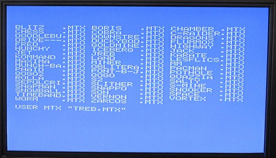
Please also note that, although the CF card contains a large
number of programs, although the majority will, not all
programs will run on the system, there are no guarantees
with the software ! Although I have tried much of the
software, there are many items that have not been tested, I
have put together
a "rough 'n' ready" list of what is on the first
partition, if you can share your experiences, I will update
the spreadsheet.
| First
Production Run (March 2017) |
| Board
Rev |
Firmware+ |
Serial |
Connector Configuration, Feedback |
Owner |
|
CFX |
Prop |
|
1.0 |
276 |
10A |
1 |
External - Fully working |
DS |
|
1.0 |
276 |
10A |
2 |
External - Fully working |
MA |
|
1.0 |
276 |
10A |
3 |
Internal - Fully working |
DS |
|
1.0 |
255 |
8 |
4 |
Internal - Fully working |
VP (it) |
|
1.0 |
263 |
9 |
5 |
External - Fully working |
BB |
|
1.0 |
276 |
10 |
6 |
Internal - Fully working |
IH |
|
1.0 |
278 |
10A |
7 |
Internal - Fully working |
MR (nz) |
|
1.0 |
106 |
11 |
8 |
External - Fully working |
AV |
|
1.0 |
161 |
11 |
9 |
Internal - Fully working |
SG (dk) |
|
1.0 |
|
|
10 |
External - Available to order |
|
|
Shipping address UK unless
otherwise noted (by Country Code) |
|
For firmware upgrades,
see here |
References:
1 Andy Key's Memotech Hardware page
2 Que Publishing, Upgrading and
Repairing PCs, 21st Edition, ISBN-13: 978-0-7897-5000-6.
Sample Chapter : The ATA/IDE Interface
|