|
 |
The Memotech MTX Series |
 |
MTX PIC Programmer
This page describes the
PIC
Programmer that Bill Brendling
demonstrated at
Memofest 2013. Bill created this in the 1990s to help with
his other electronic projects, giving him the ability to
program PIC
devices using his MTX via the parallel port.
Bill produced his own PCB for the design, there are a number of
ways of doing this for the hobbyist, just
Google "pcb diy"
for more information.
Briefly, one way of making a home-brew PCB starts with a board that is
completely copper clad, the track layout is "printed" onto the
copper board and forms a protective layer over the copper that is
to become the tracks. An etching solution, such as ferric
chloride, is then used to strip off the exposed
areas of copper, leaving the tracks in place, before finally, the holes
are drilled by hand.
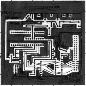
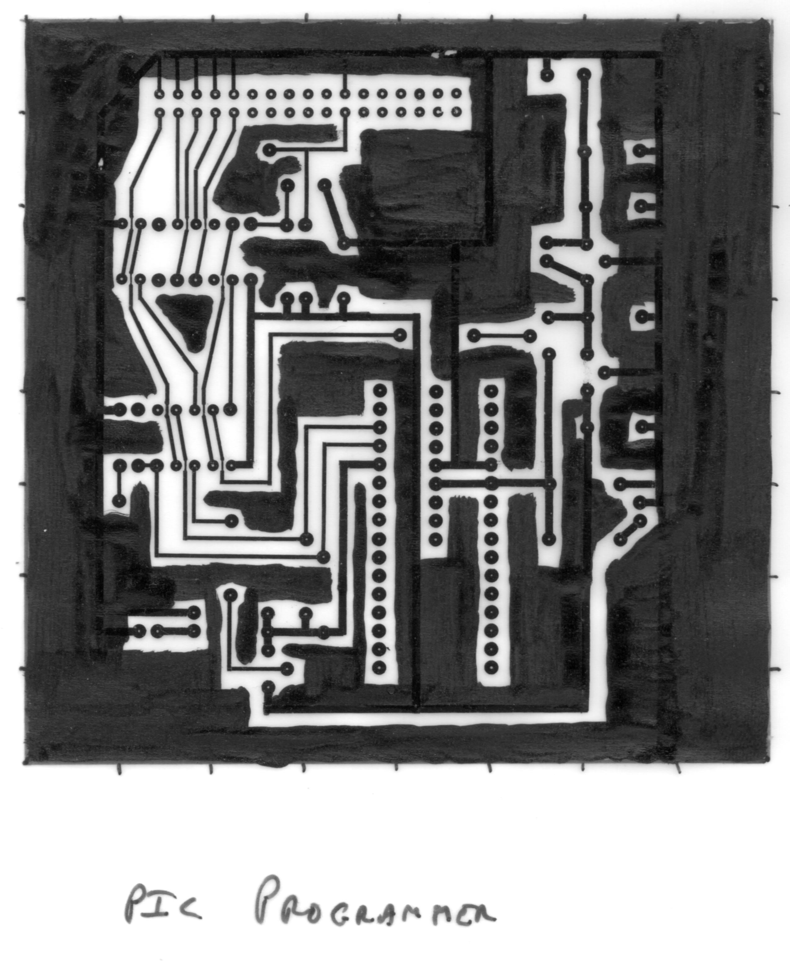
Describing how the original PCB was produced, Bill recalls that
"the layout for the PCB was done with transfers
and was photo-etched.
|
Most
of the board area is blacked out, and so remains
copper. There are three reasons for that:
-
1. It saves on Ferric Chloride during the
etching.
-
2. It often gives better results, While trying
to etch away large areas of copper, the edges of
all the tracks are also being attacked, and
narrow tracks, such as between IC pins, can be
etched right through.
-
3. Having a large ground plane does not hurt
anyway. "
|
|
 |
|
 |
|
 |
|
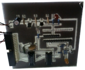
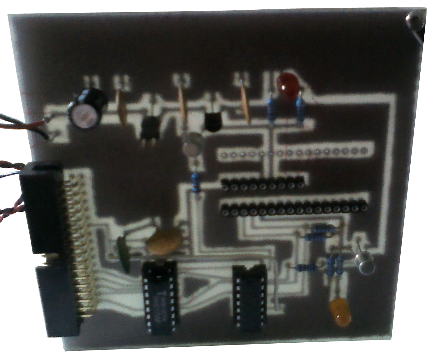
The base board is fibreglass and is
translucent, holding the board up to the light, the
areas where the copper has be removed can be clearly
seen. |
|
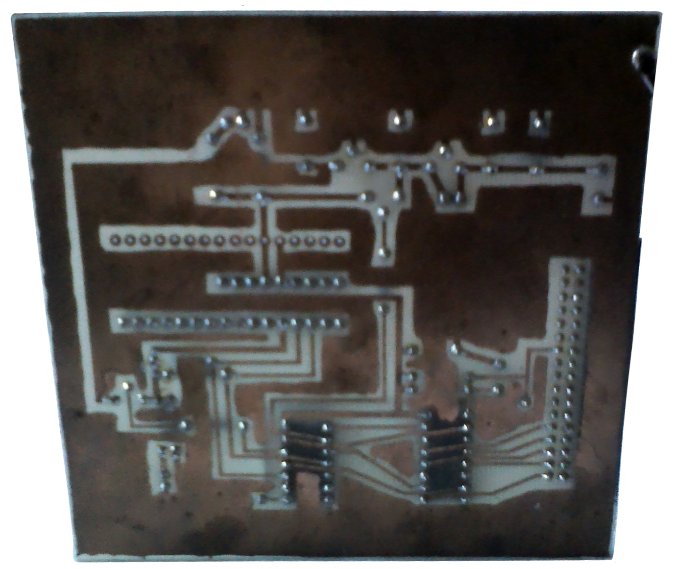
The rear of the board, showing the
tracks and bare copper areas more clearly |
The software to drive the programmer is available as a
Type 07 image
or a PC Zip
File
Bill has provided some notes on the original design . . . . .
[The PIC programmer] "is the simpler circuit, as
the PIC chips I use so far (16c84 and 16f877) use a serial
programming algorithm. The four lower bits of the printer data
port are used to drive the programming:
My circuit uses the printer strobe line to latch
this data, which in hindsight is probably unnecessary.
The CP/M software (BLOWPIC hexfile) that drives
the programmer uses the Memotech CTC chip to time the
programming pulses. One word of caution: the programmer software
assumes the hex file format generated by my PICASM software,
which is not consistent with that produced by Microchip
MPASM or the open source
GPASM. The issue
was caused by lack of readily available information on the
format used at the time I developed the software. Since I now
use GPASM and GPSIM on Linux to develop PIC software, I will fix
that at some time, but have not yet got around to it."
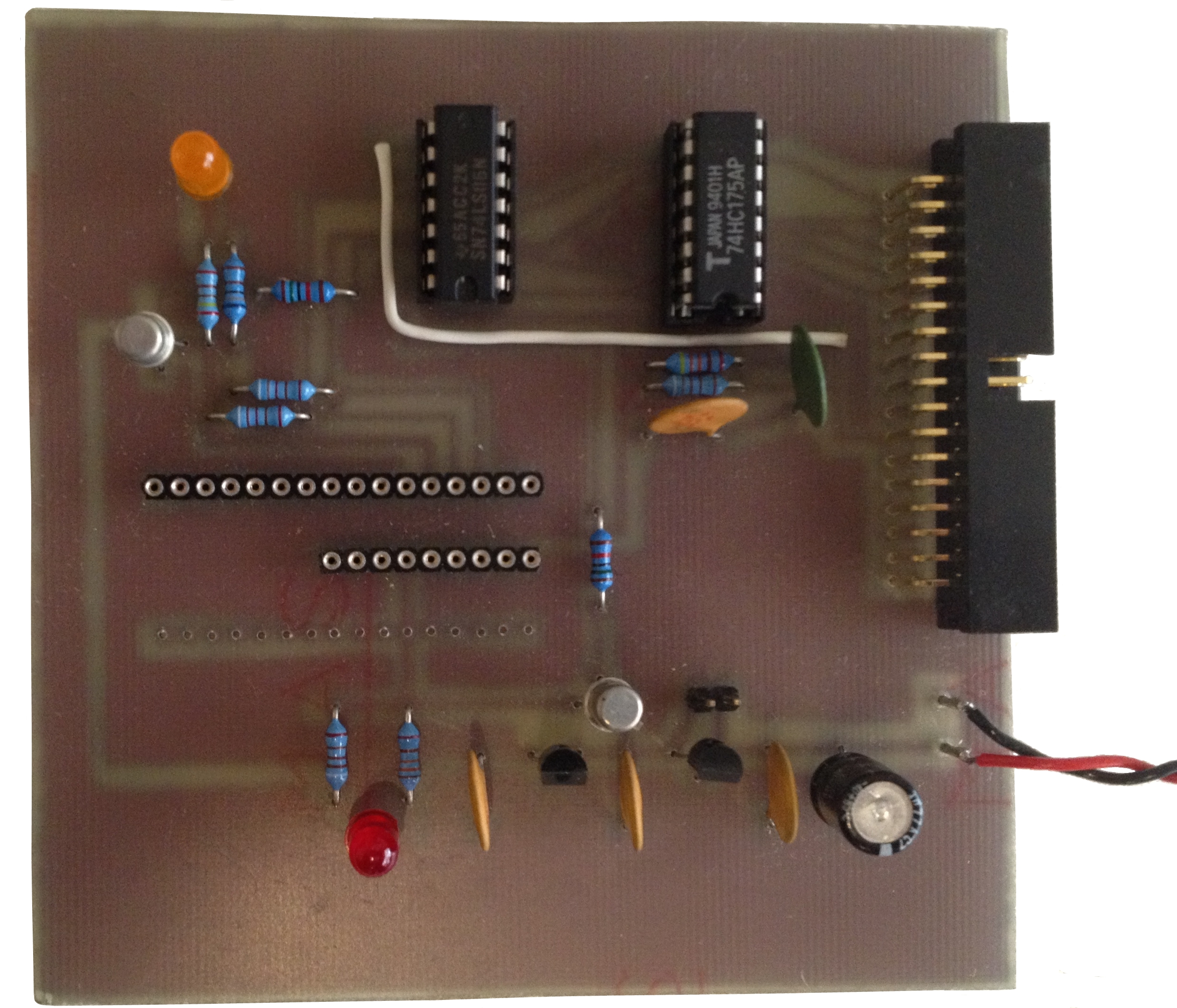
"A couple of points to add to the circuit
description. It is important that the inverter chip used is the
variety with open collector output (or open drain in the HC
equivalent) for two reasons:
-
When the input of U1A is low, the output
will drift up to +12v.
-
When the input of U1D is low, the output is
high impedance, only pulled high by R9. This means that, in
this state, the PIC can readily drive the pin high or low
when outputting data, which is then fed back to the Memotech
via U1E and the printer BUSY line.
The cable I use to connect either of my
programmers to the Memotech is a ribbon cable, with IDC
connectors attached opposite ways around at the two ends (pin 1
at one end attached to pin 26 at the other). This has the
advantage of bringing the data lines onto the upper row of
contacts on the right angle connector, where they are easier to
connect to.
LNK1 is inserted if running the unit off a
regulated 12 volt supply, or removed if using an unregulated
supply of 15 volts or greater."
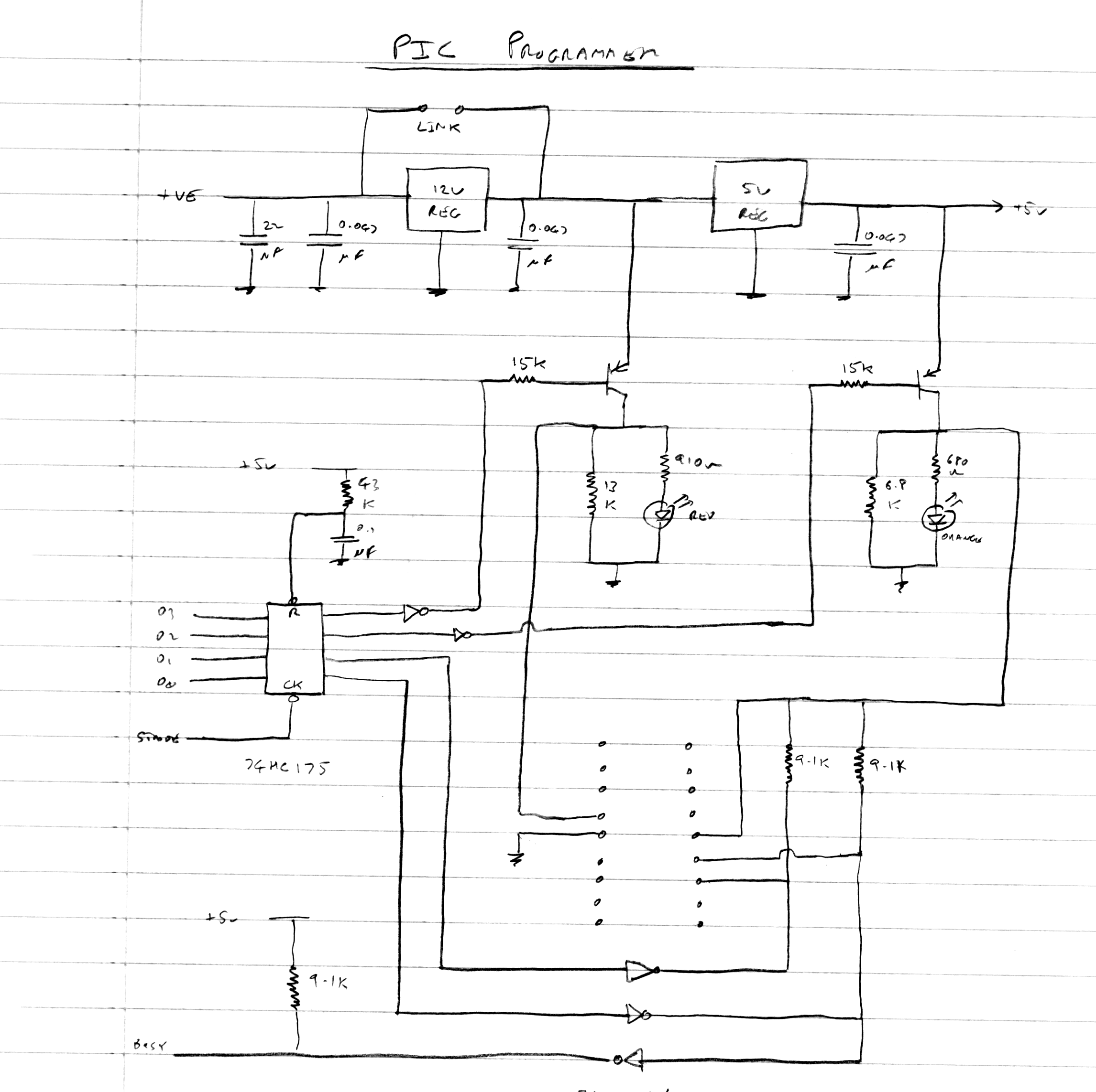
Bill has provided a
sketch of the original design. I have taken the sketch and
drawn a schematic using
KiCAD, note the KiCad schematic reorders the
pins on the interface connector for a straight through cable
between the MTX printer port and the programmer.
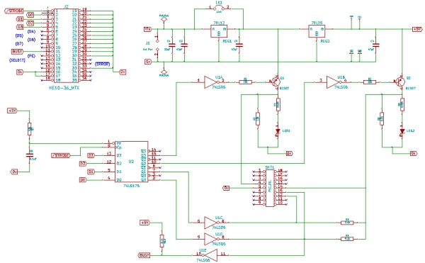
Click on the image to
open as a PDF
|

