|
 |
The Memotech MTX Series |
 |
MTX EPROM Programmer
This page describes the EPROM Programmer that Bill Brendling
demonstrated at
Memofest 2013. Bill created this in the 1980s to help with
his other electronic projects, giving him the ability to
program EPROM
devices using his MTX via the parallel port.
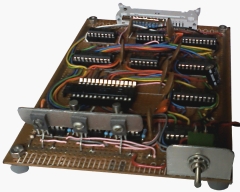
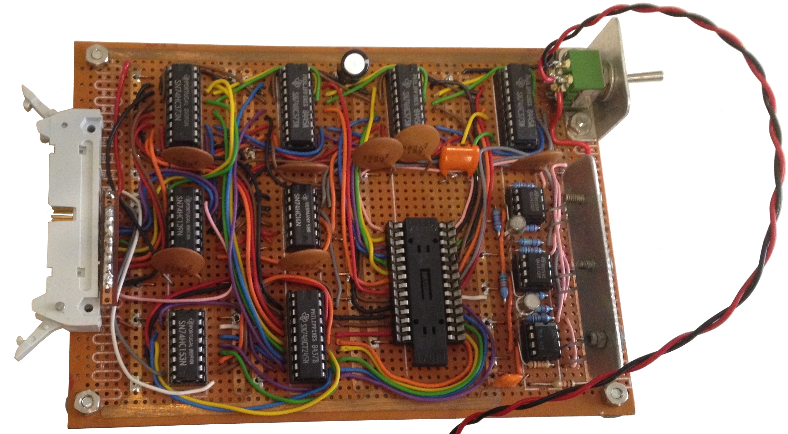
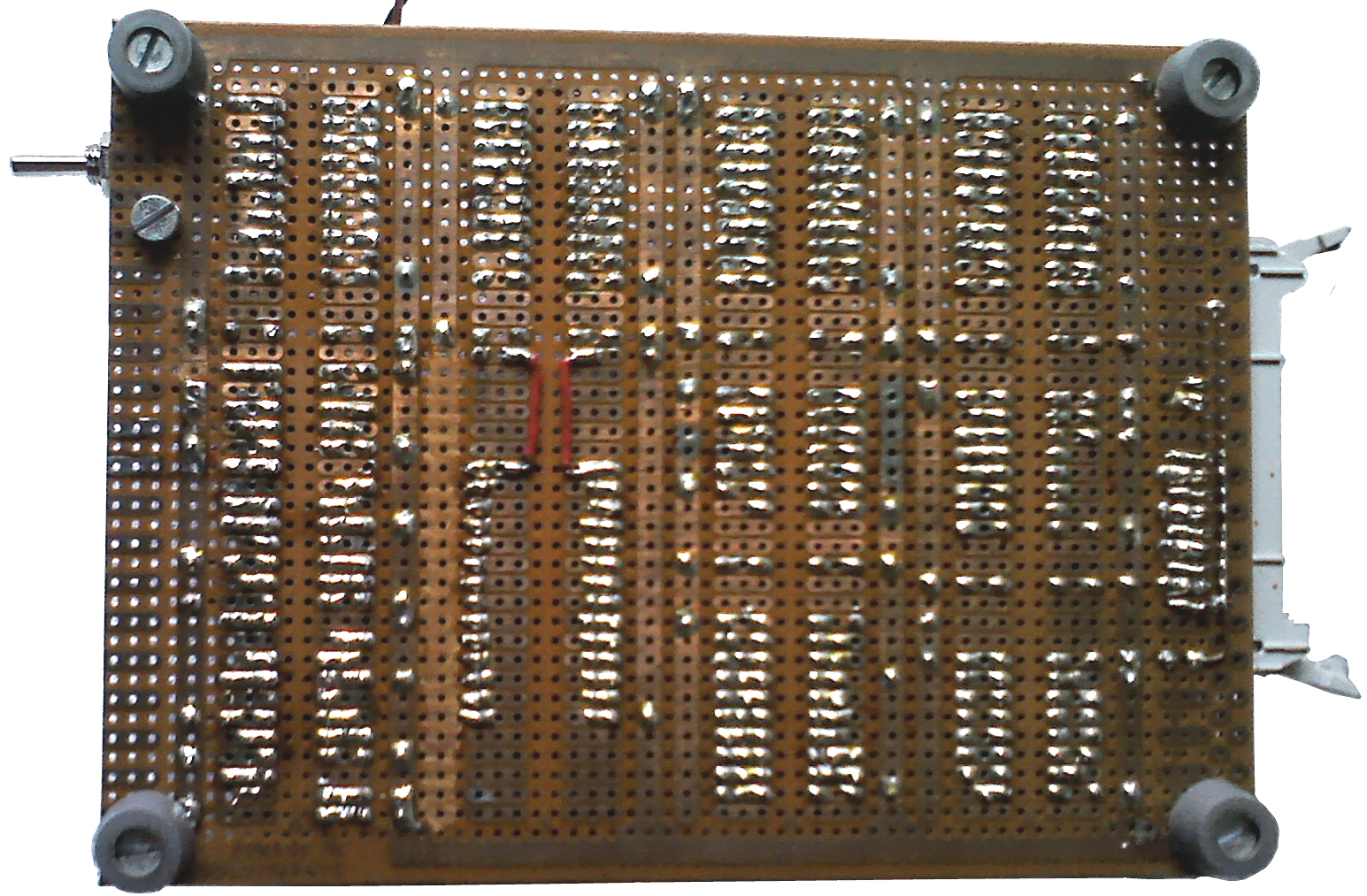
The board was built on a prototyping board as shown in the
photo.
| Bill has provided a couple of additional photos
to show some of the details of the board. In the
foreground of this photo you can see the three
output power transistors bolted to the vertical
heatsink.
In the background you can see Bill's d.i.y. SIL
resistor package for the pull-up resistors on the
printer port data and strobe lines. |
 |
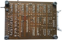
| The solder side of the board |
 |
Bill has also provided some notes on the original design . . . . .
[The EPROM Programmer is more complex than the
PIC programmer design,] "as
27C64 or 27C128 EPROMs (which I use) require 8 data bits and 13
or 14 address bits simultaneously. In order to achieve this I
use the top two bits of the printer data to address four six-bit
latches, giving a total of 24 bits.
These are used as follows:
| Latch 3: |
|
| D5 |
Program enable: High to program, low
to read back. |
| D4 |
Unused (could be used for another
address bit, but 27C256 chips have a different
programming voltage arrangement) |
| D0 – D3 |
EEPROM address bits A10 to A13. |
| |
|
| Latch 2: |
|
| D0 – D5 |
EEPROM address bits A4 to A9. |
| |
|
|
Latch 1: |
|
| D2 – D5 |
EEPROM address bits A0 to A3. |
| D0 – D1 |
During write: EEPROM data bits D6
and D7. During read, multiplexes pairs of data bits
onto the Memotech printer port PE and SLCT lines.
|
| |
|
| Latch 0: |
|
| D0 – D5 |
EEPROM data bits D0 to D5. Also, the
STROBE on this latch applies the programming pulse
to the EEPROM. |
During programming, the program enable bit (D7
on latch 3), address bits and top two data bits are first
written to latches 1-3, then the remaining six data bits are
output to the printer port, and a timed STROBE pulse applied
(timed by CTC).
To read data back, the program enable bit is
cleared and the address bits written to latches 1-3. The bottom
two bits of latch 1 are used to step through the output byte,
two bits at a time. Do not use latch 0 during reading.
The following CP/M programs are used to control
the EPROM programmer:
| BLOWPROM hexfile |
Program an EPROM. |
| |
|
| DUMPPROM outfile size |
Read the contents of an EPROM back into a hex
file. The size is specified in Kbytes (so usually
either 8 or 16). |
| |
|
| READPROM |
Interactive display of pages from an EPROM (hex
& ASCII). |
| |
|
The software is available as a
Type 07 image
or a PC Zip
File
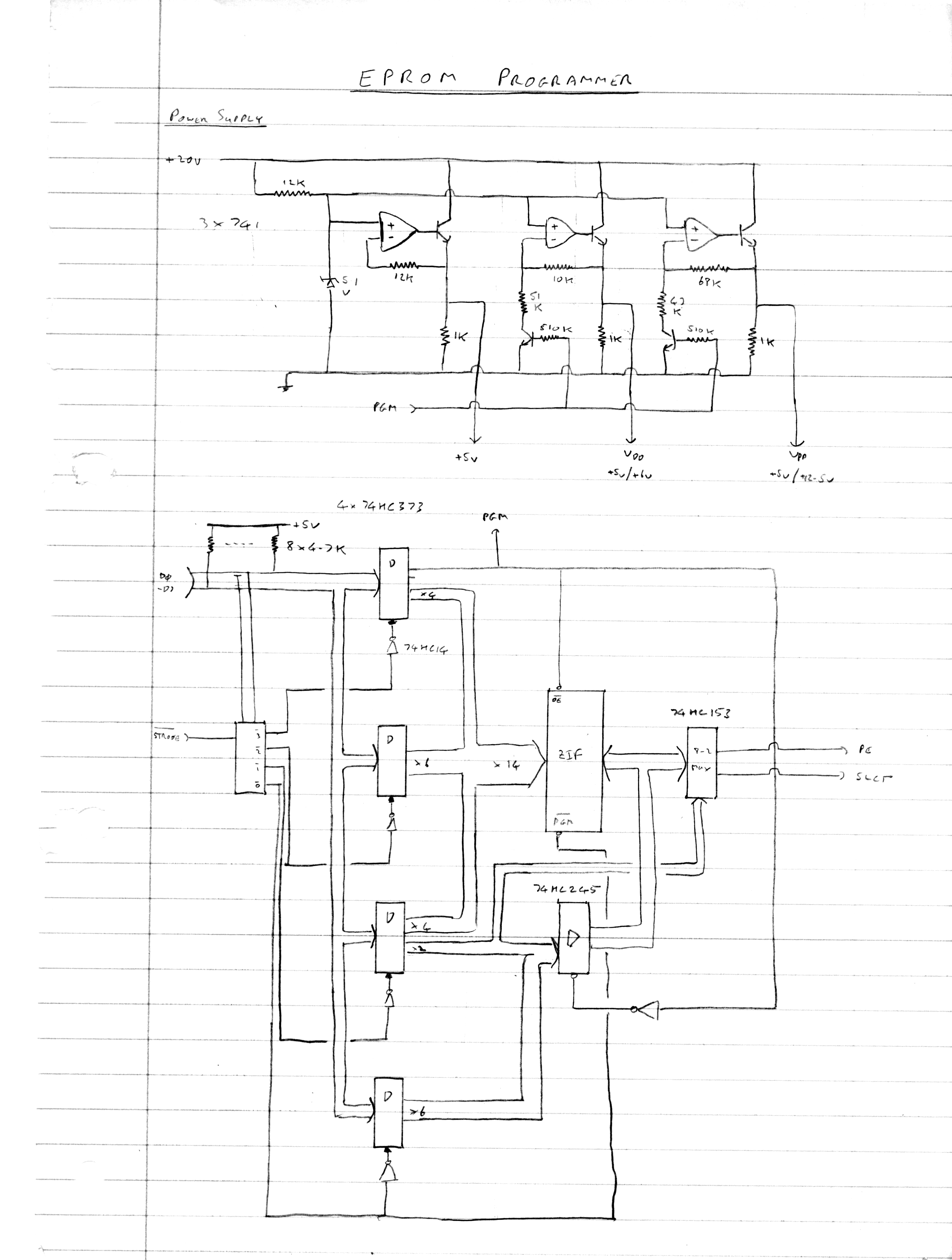
Bill has provided a sketch of the original design,
I have taken the sketch and drawn a schematic using
KiCAD, note the KiCad schematic reorders the
pins on the interface connector for a straight through cable
between the MTX printer port and the programmer.
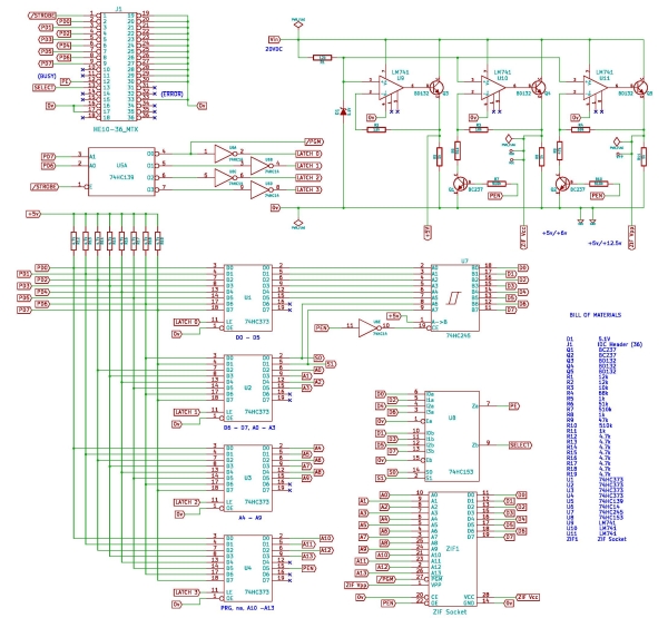
Click on the image to
open as a PDF
|


