|
 |
The Memotech MTX Series |
 |
MTX PC Keyboard Interface
Board Design
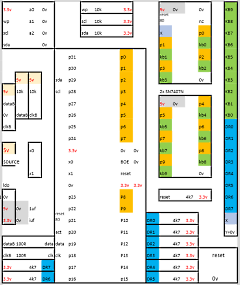
Martin does
his prototype board layouts using Excel, this helps him
place the components on a matrix representing his
prototype board, but they are not schematic diagrams in
the usual sense.
Note: the layout is drawn as reference to be used for
soldering, so the view is from the underside of the
board, i.e., the components are a mirror image of the
normal footprints.
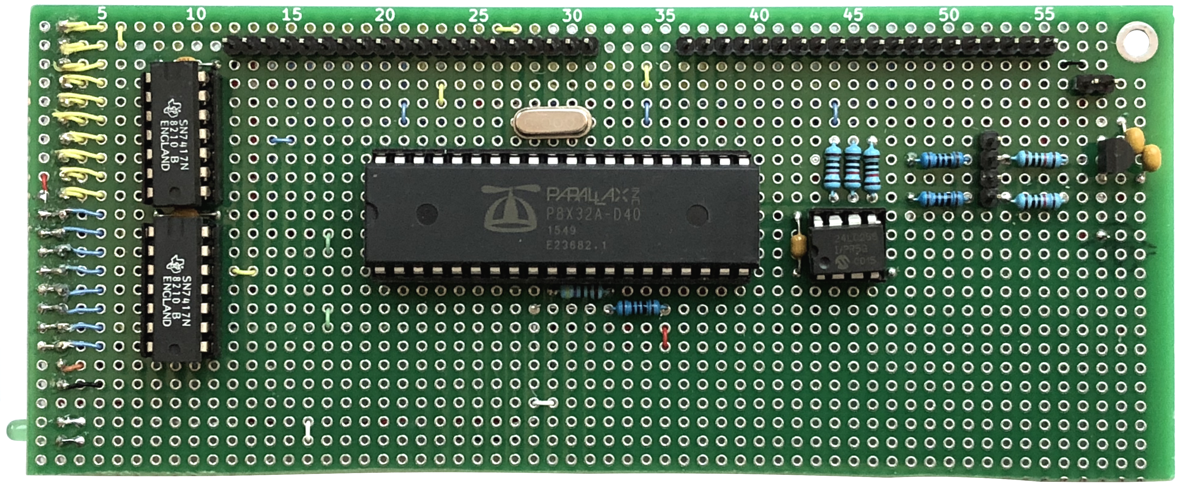
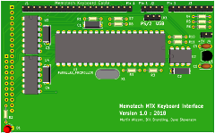
This is the layout for
Martin's prototype board, the major components being the
Propeller, associated serial EPROM and two 74x7
non-inverting buffers. |
 |
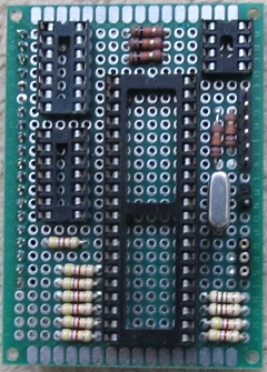
The
components placed and soldered onto a small prototype
board that Martin happened to have available.
The board sits conveniently on top of the MTX keyboard
connector and would allow the MTX keyboard shell to be
closed if required but does not have the facility to
connect the MTX keyboard at the same time as the PS/2
interface board. |
 |
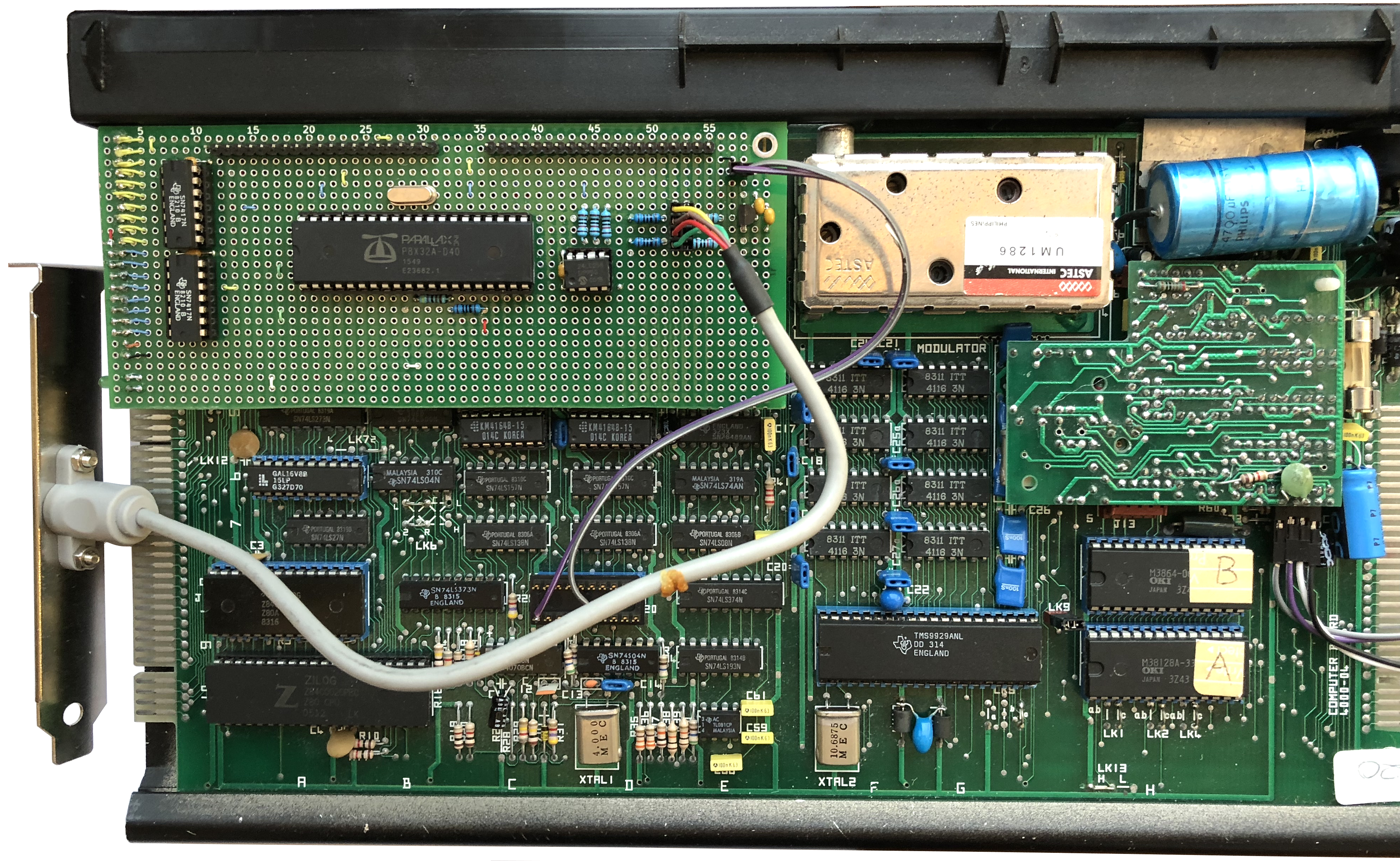
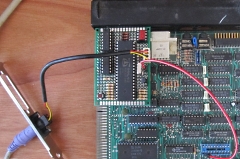
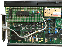
Martin's
board fitted to the MTX and attached to a PC PS/2
keyboard I/O slot adapter panel.
You can also see
the flying lead connected to the MTX User Port socket
from where Martin has picked up 5VDC for the board. |
 |
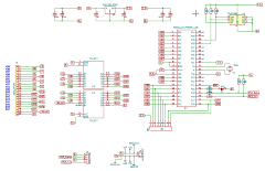
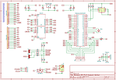
I took
Martin's component layout and converted it to a KiCad
schematic as shown.
As noted above, plugging
into the MTX keyboard connector prevents the MTX keyboard from being connected at the same time.
|
 |
When the Propeller
keyboard interface is incorporated into MTXPlus+ it will
connect in parallel with the existing MTX matrix
keyboard interface, allowing a PS/2 keyboard and an
original MTX keyboard to be connected at the same time.
I decided that it would be nice to have a similar setup
on an original MTX so that a PS/2 keyboard could be
connected as and when required, without needing to open
up the computer.
The easiest method of
connecting a PS/2 keyboard would be to have a PS/2
connector on a trailing lead exiting the rear of the
case, but I also though that it would be nice to be able
to include a PS/2 connector on the MTX itself.
There are a couple of options to achieve this, either by
drilling an additional hole in the rear plastic I/O port
panel, or by drilling one of the end plates. I was not
keen on the first method, but was happier drilling one
of the endplates as they would be much easier to replace
if the keyboard connector was removed in the future. The
left hand side end plate is not a good choice as it
would be obstructed by any MTX expansion hardware; the
right hand side end plate is a better option.
I
also considered allowing the PS/2 keyboard PCB to to
mounted to the right of the computer board(s) such that
the PS/2 connector could be mounted on the PCB, rather
than needing a flying lead. If the PCB was mounted at
the right hand side of the case, then IDC cables would
be needed between the existing keyboard, computer
keyboard connector and the new PCB.
|
| To cater
for these options, I added additional headers to my
design to allow the MTX keyboard to be connected
simultaneously with the PS/2 keyboard and/or to run an
IDC cable from the right hand side of the case to
the MTX keyboard connector. |
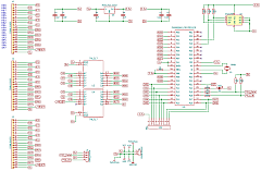 |
| These
options meant that my prototype design was quite a bit
larger than Martin's to allow space for the additional
pin headers to be located in the deepest part of the
case (at the rear). Whilst this design gives the most
flexibility, it does mean that the board becomes quite
large and exceeds the target price point for the PCB
manufacturer that I use (<100mm). |
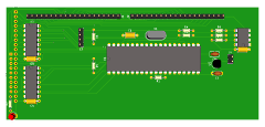 |
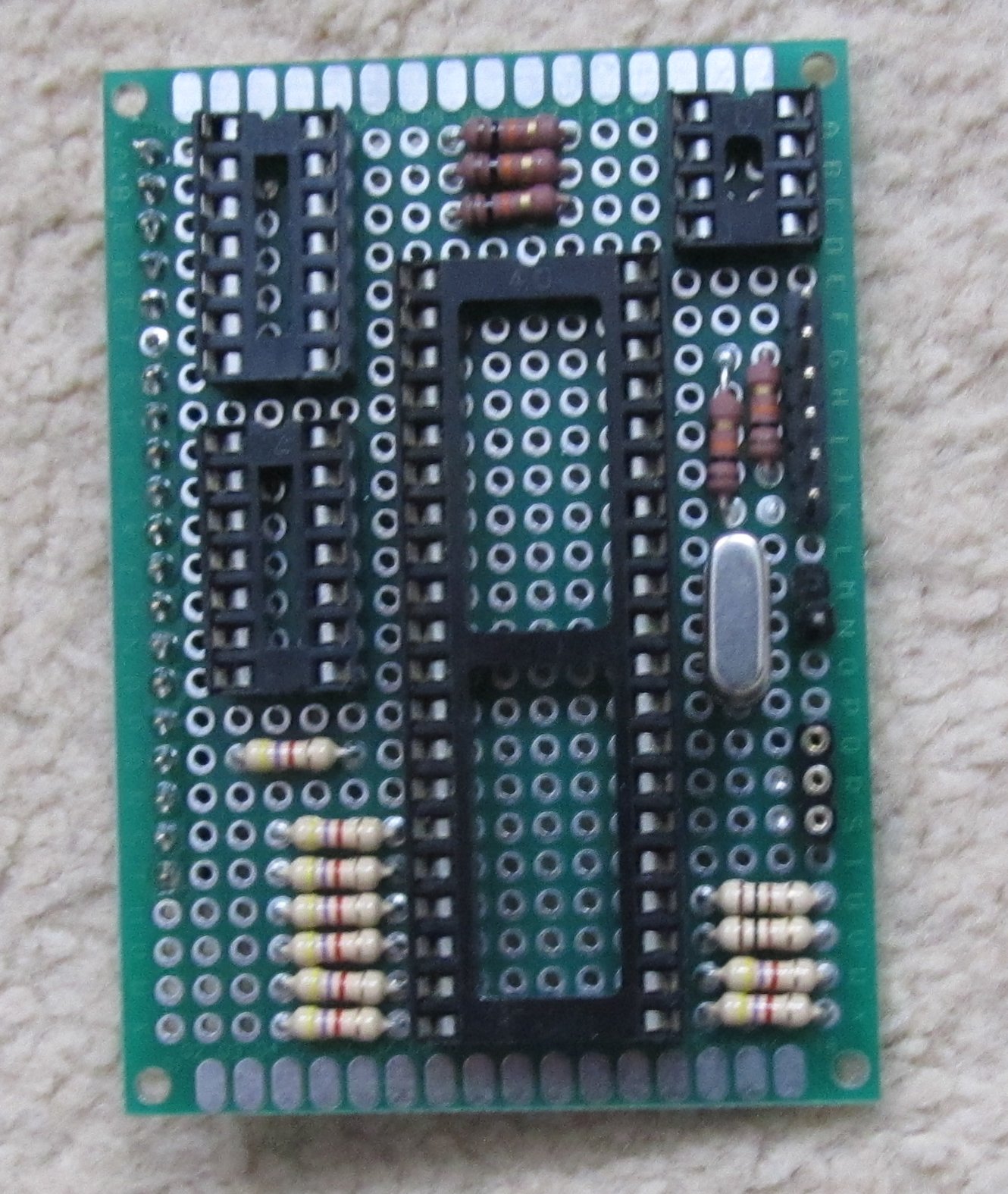
My
prototype board - with a couple of changes from the 3D
model for ease of construction.
I found that the
Propeller and EPROM needed to be a little further
towards the top of the board than Martin's prototype to
allow adequate clearance when the MTX keyboard was
fitted. |
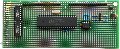 |
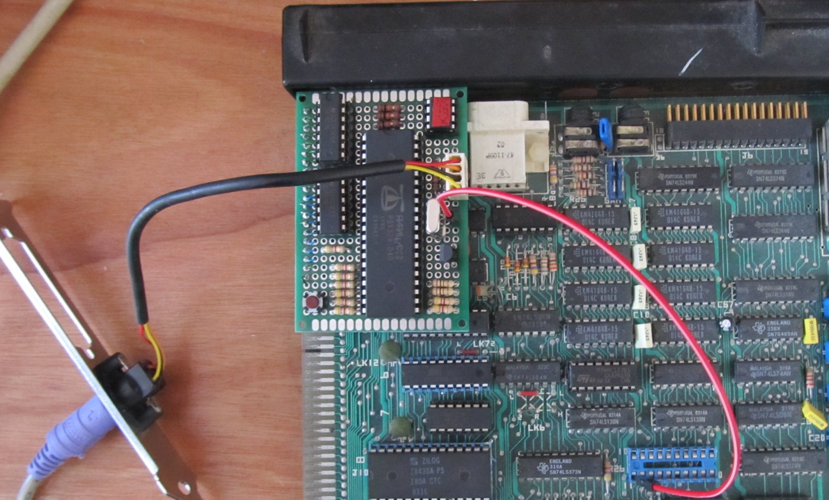
My
prototype board fitted to the MTX keyboard connector.
You can see the my PC PS/2 keyboard I/O slot adapter
panel attached and below the PS/2 cable, the 20 pin DIP
header that I have attached to the User Port socket. (Bad
Design ! see below)
Although the MTX keyboard connector pin 20 provides
0v, in addition to the 5v connection on pin 20 of
the User port, I have also picked up 0v from pin 16,
this provides a little more strain relief on the jumper
wire, rather than just having it connected to the 5v
pin. |
 |
After a little
debugging and editing of the code, Bill's Propeller code
worked very well, with the same limitations on the
mapping between the PC keyboard and the MTX ROM that
exist in MEMU
on which the Propeller code is based.
These
issues are described in the
keyboard section on the
MEMU
emulation page of Andy's site and are associated
with issues related to shifted and unshifted keys.
Quoting from Andy's page, "... to type certain MTX
characters, you must type different things on the host
PC keyboard. This remapping is done to ensure an
unshifted host PC keypress corresponds to an unshifted
MTX keypress and a shifted host PC keypress
corresponds to a shifted MTX keypress." and "the whole
host PC keypad maps to the whole MTX keypad, based on
key position, not what is written on the keys"
"The effect of the shift-state problem :- "
|
Use host keypress |
To produce MTX
keystroke |
| ^ |
= |
| = |
^ |
| ' |
@ |
| @ |
' |
| # |
: |
|
<shift> ` |
` |
This behavior is not ideal, but is considered to be
the most practical way of using a PC keyboard on the MTX
without making changes to the MTX ROM. The
difference between the effect of a keypress and what is
written on the keys is most noticeable with the PC
numeric keypad - see the diagram at the top of the page
for further detail.
However, Martin
has developed patches for the MTX ROM to map the PC
keyboard characters to the desired MTX keystroke when
the keyboard "Scroll Lock" mode is active. An updated
ROM image is available below.
In standard mode the system works as now with key
mismatches. In "Scroll Lock" mode the main keyboard
keycaps all match except "back quote". (The keypad in
shift mode is still offset because the cursor keys are
aligned.)
For MTX users with CP/M or SDX disk
systems, Bill has written loadable
drivers that enable the "Scroll Lock" mapping mode
to be used without requiring changes to the MTX ROM.
For CP/M this works by patching the CP/M BIOS in
high memory. For SDX BASIC, a small routine is loaded
between the sound buffers and system variables, which
hooks into an SDX call vector to provide the additional
keyboard decoding.
5V Power Connection
Although the User Port was used to provide the 5VDC
to the boards for testing, we did not pay enough
attention to the restriction included in the MTX
Operator's Manual - the User Port is only specified as
being able to supply 20mA - the propeller and more
significantly, the PC keyboard requires considerably
more than that. Inspection of the MTX computer board
shows that the 5V supply to the User Port is on a very
thin PCB trace - I suspect that it was this that set the
maximum current available from the User Port. It would
be a relatively easy task to solder an additional wire
from a 5V connection to the 20 way socket, but that
would prevent the PCB from being "plug & play". Instead,
we will likely use a test clip to pick up 5VDC from a
convenient point on the MTX computer board.
(Taking power from the MTX PCB may be problematic if the
computer is fully loaded with internal and external
expansion boards. If the MTX 5V supply is close to
capacity, then an external 5V supply would be needed.) |
Inclusion of USB
Keyboard Compatibility
The prototypes that Martin and I had built operated as intended, however, I had not appreciated that
PS/2 keyboards were as obsolete as they actually are and
the difficulties that might bring when implementing this
project on a wider basis, should it be of interest to
others. Whilst legacy PS/2 keyboards are still
available, it appears that the PS/2 adapter plates that
Marin and I had used are pretty much impossible to find.
During my testing, I used a legacy PS/2 compatible
keyboard with 6-pin mini-DIN connector. Bill and Martin
had used USB keyboards with "dumb" USB to PS/2 adapters
which worked perfectly. When I tried to use one of my
USB keyboards in the same way, the system failed to
recognise the keyboard and respond to key presses. As it
turns out, older USB keyboards can detect when a PS/2
interface is being used and use the PS/2 protocol so a
passive adapter works fine. Newer USB keyboards do not
all support the PS/2 protocol and an active adapter
would be needed to do protocol conversion.
Bill
had predicted that this may be an issue and had already
found USB interface code for the propeller that was
"worth thinking about". It was obvious that my original
intention to have a PS/2 compatible interface was short
sighted and a USB keyboard interface is pretty much
essential. With that in mind, I asked Bill if he could look
at developing the code for a USB interface too.
|
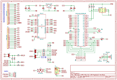
Based on
Bill's initial research - a proposed design for a dual
function PCB.
It seems that the USB interface
needed the USB signal lines connected to low address pins
on the Propeller (A0-A7) and the USB and PS/2 interfaces
use different resistor values and voltage levels. This
design allowed the pull-ups / downs to be selected by
jumpers. |
 |
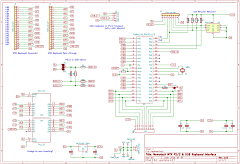
We hoped
that it may have been
possible to find a pair of resistor values that can work
for PS/2 or USB keyboards (to be determined by testing),
in which case, it would be possible to simplify the
design as shown here, where only a single jumper is
needed to select the keyboard type.
The status of
the single jumper could also be used to identify the
type of keyboard (PS/2 or USB) so that the Propeller
could choose the appropriate code to execute. |
 |
Testing on
the prototypes suggested that the PS/2 resistor values
would also work for USB keyboards, so a single set of
resistors has been configured in the "final" schematic
used to generate a prototype PCB.
As of March
2018, the prototype boards had been proven to work in
PS/2 or USB mode, the dual mode code had not been tested
but as the hardware appeared to work, I committed a trial
run of PCBs to manufacturing. |
 |
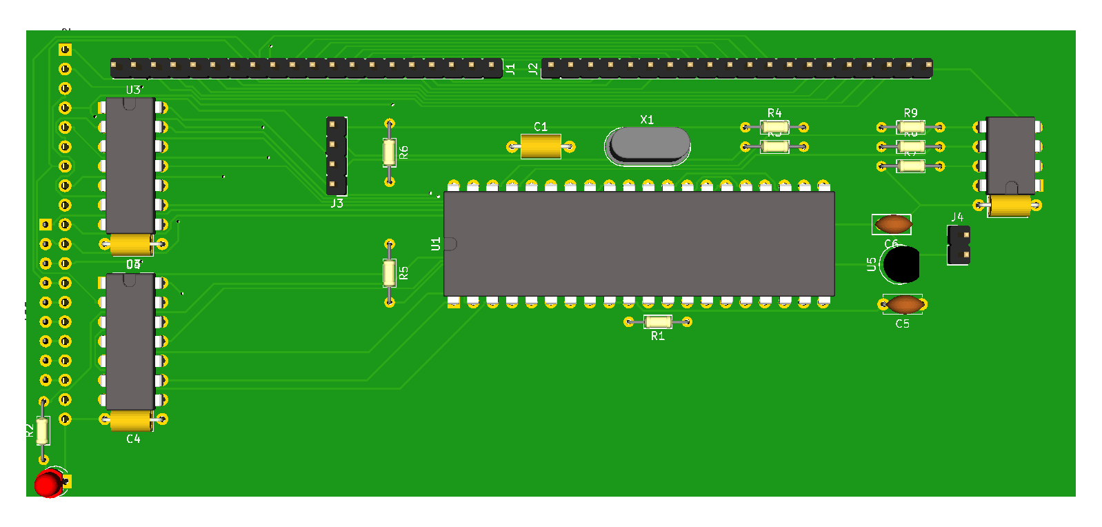
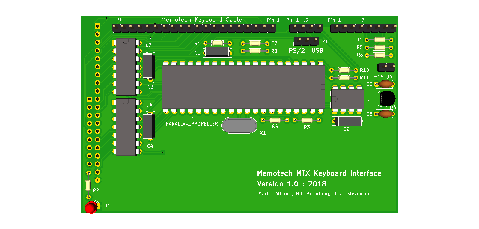
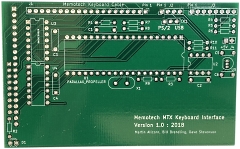
| The KiCad
3D model of the PCB. The components are pushed as far up
the PCB as possible and the board size reduced to 100mm
wide to minimise the PCB production cost. |
 |
The first
run of the PCB has identified a couple of minor issues .
. .
1. The DIP-14 sockets are too close together,
which makes installing the buffers in sockets a tight,
but workable, fit. (The tolerances in the sockets allows
the chips to be installed at the opposite ends of the
sockets.)
2. The top DIP-14 socket is too close to
the MTX keyboard pass-through connector, but bending the
pins at about 30 degrees allows the connector to be
plugged in and the keyboards operated in parallel. |
 |
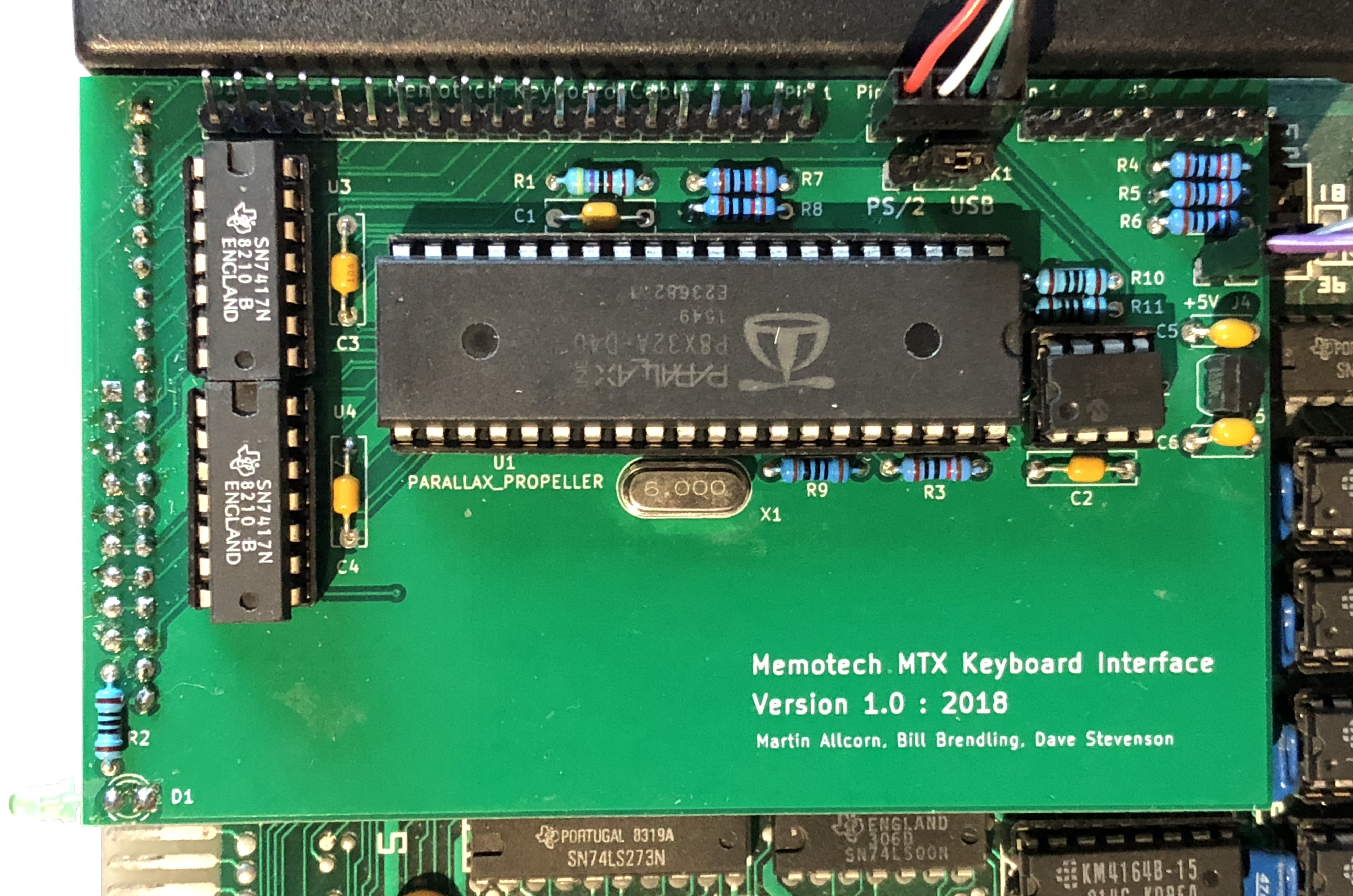
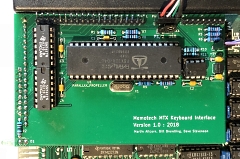
Assembled
PCB, fitted to MTX.
The MTX keyboard has been
disconnected for the photo, but fits without problem
with the pins on the pass-through connector bent
slightly as shown.
(On this board, the activity
LED is orientated so that I could see it more easily for
testing, normally, it will be mounted on the surface of
the PCB.) |
 |
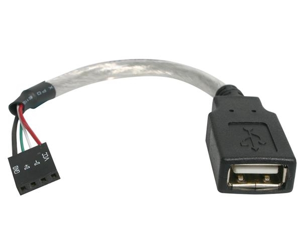
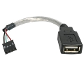
A typical
PC Motherboard USB header header is shown opposite. It
is designed to support two USB connections; there are a
number of varieties of mating cables which support 1
(4/5 pin cables) or 2 (9 pin cable) USB devices. Most of
these cables should be suitable for use with the MTX
keyboard PCB USB header when connected appropriately.
NB : The keyboard PCB USB pin
header is not keyed, Pin 1 is the left hand pin, closest
to the MTX keyboard pass through connector. |
 |
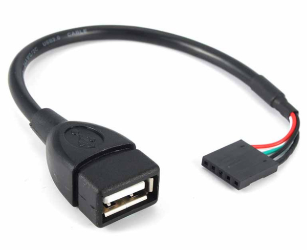
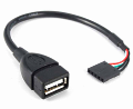
| Single USB
adapter cables are available in 4 and 5 pin varieties.
Either may be used with pin 1 (5V) connected to pin 1 of
the header. If a 5 pin cable is used, pin 5 (usually a
slightly thicker core used for the cable screen) will be
unconnected and overhang the keyboard pin header. |
  |
Future Development
MTX Mouse interface ? (Cancelled)
Martin has been working on an additional hardware interface
to support the use of a PC PS/2 mouse with the MTX. To avoid the
need for new driver software or modifications to applications
software and games, Martin's interface is designed to mimic the
cursor keys in the same way as the Memtoech joystick interfaces
worked. Martin's design uses an Atmel ATMega328
microcontroller and supporting GAL and also connects in parallel
with the existing MTX keyboard (and PC keyboard interface if
fitted).
Whilst Martin's mouse interface is a nice technical solution,
I am not sure whether there is enough demand to justify making
it a "product". However, it **may** be possible to add mouse
functionality to the keyboard interface without having to make
significant hardware modifications. Adding a PS/2 mouse appears
to be relatively straightforward and likely to fit in the
available free space of the Propeller. Adding a USB mouse is
more complex and further work is required to determine whether
it is possible.
In either case, it will not be possible to
upgrade a keyboard only PCB to include a PS/2 and/or USB mouse.
Update
Based on
Martin's results when testing his mouse interface with
NewWord, it is apparent that using the ROM keyboard scanning
functions to update the mouse position is too slow to be
practical - certainly with CP/M software. Given that the
limitation appears to be the keyboard scanning speed, using the
Propeller to provide the interface to the mouse would also have
the same issues as the AVR interface.
|