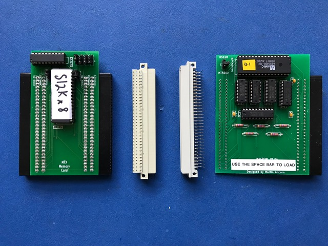
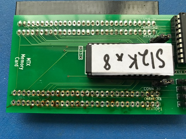
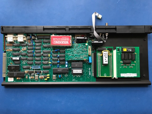
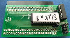
I wanted to put the MAGROM inside the
case of my MTX500, but as it already had Andy's MTX Memory Card,
a few modifications were needed to accomplish this. Dave had
already managed to connect the memory card with the CFX ( http://primrosebank.net/computers/mtx/projects/cfx/cfx_special.htm )
so this paved the way for my modification.
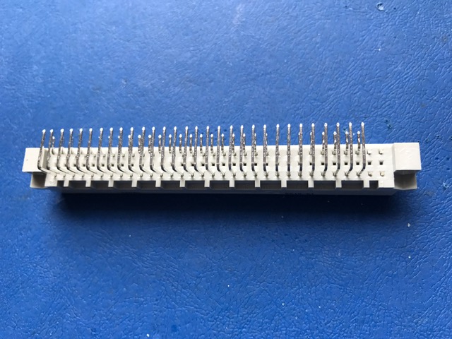
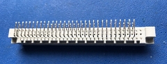
As with Dave's modification, I used the
same 2 row, 64 pin DIN 41612 connectors, which he very kindly
shipped over to me as I had trouble locating them over here in
the US.
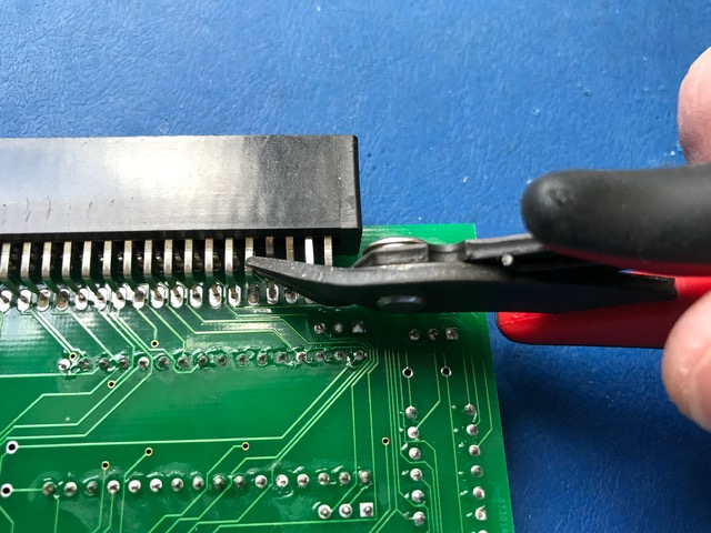
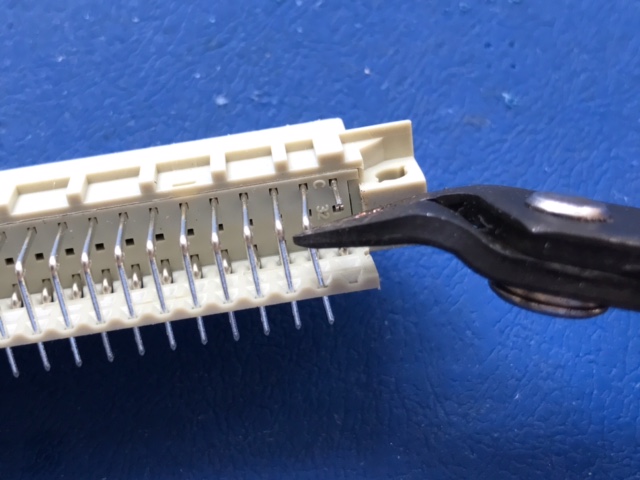
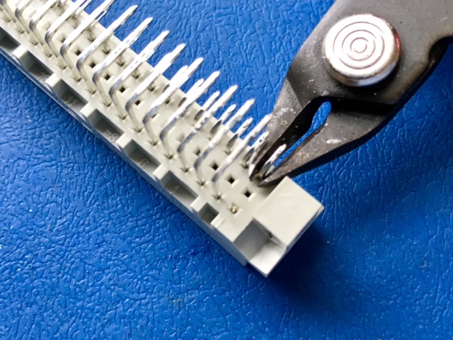
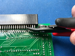
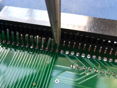
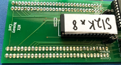
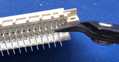
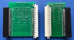
The first
task is to remove the right hand edge connector of the
memory board. I cut just on the right angle which leaves
enough of the metal pin behind for removal.
This
was repeated along the first row. |
 |
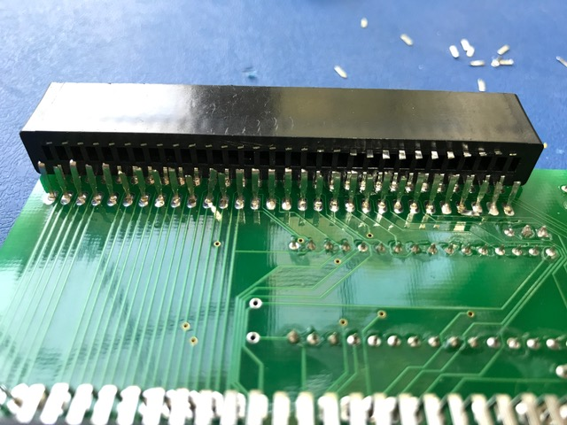
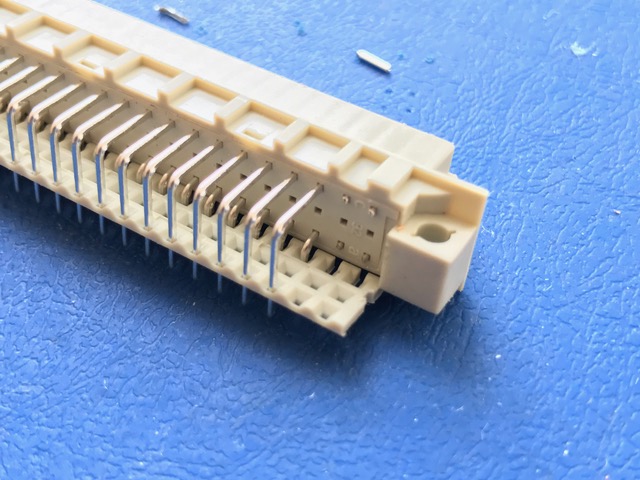
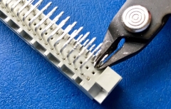
| Cutting as
close to the edge connector as possible, I removed the
remaining bits of metal. This makes accessing the pin
using long nose pliers a lot easier. |
 |
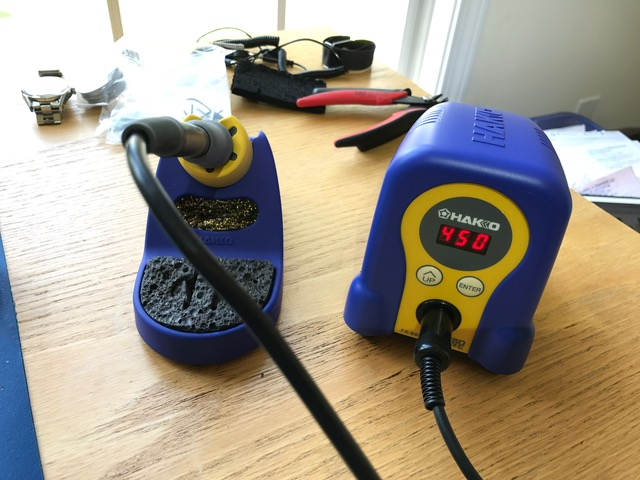
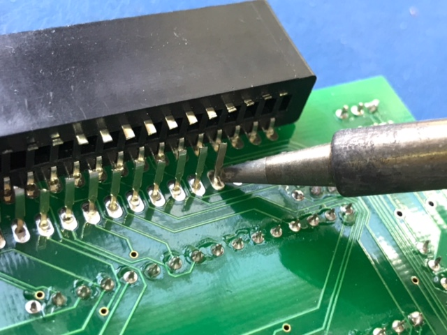
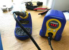
This is my
new soldering station - a Hakko FX-888D.
I
cannot recommend it enough. It has transformed my
soldering skills immensely. No more horrible looking
"blobs". |
 |
| To remove
the pin, I heated the solder joint until it melted and
gently removed it using the long nose pliers. |
 |
As one
hand was holding the camera, I can't show the soldering
iron melting the solder at the same time the pin was
removed. You get the idea.
This was repeated
for the remaining cut pins. |
 |
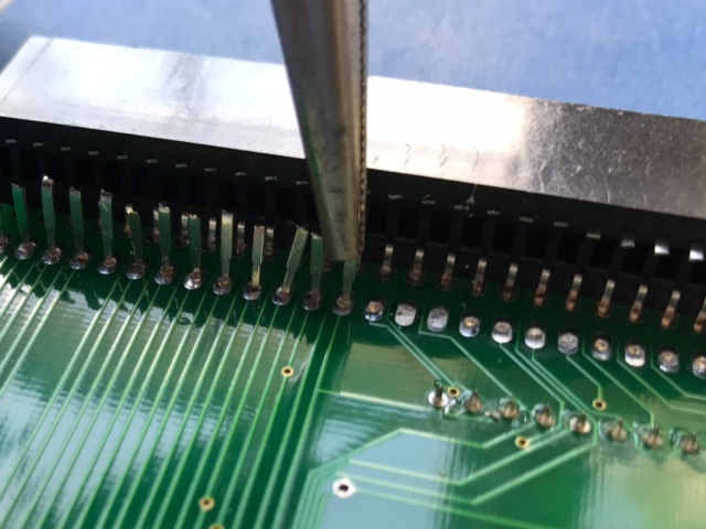
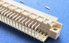
| The second
row was a bit tricky to cut, but I was able to twist the
edge connector up slightly to allow me to cut the pins
as close to the connector as possible. |
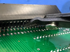 |
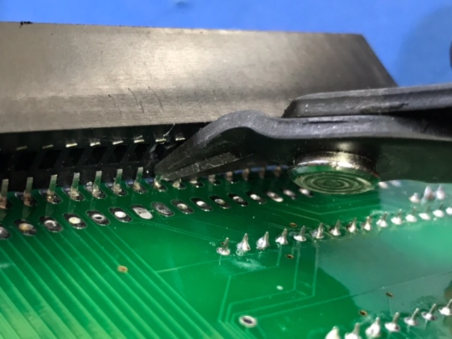
| Connector
removed. I started cutting the pins too close to the
board which made them a bit tricky to remove before I
twisted the connector as shown here. |
 |
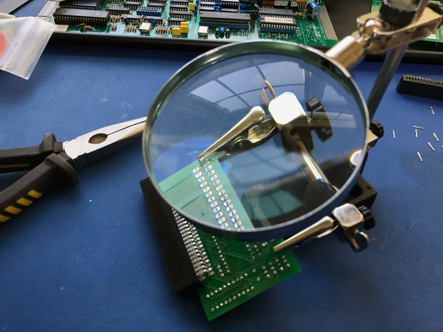
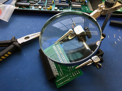
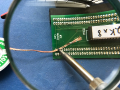
| My Rolson
Helping Hand makes extracting the pins a breeze as it
keeps the memory card steady and the magnifying glass
allows me to see what I'm doing! |
 |
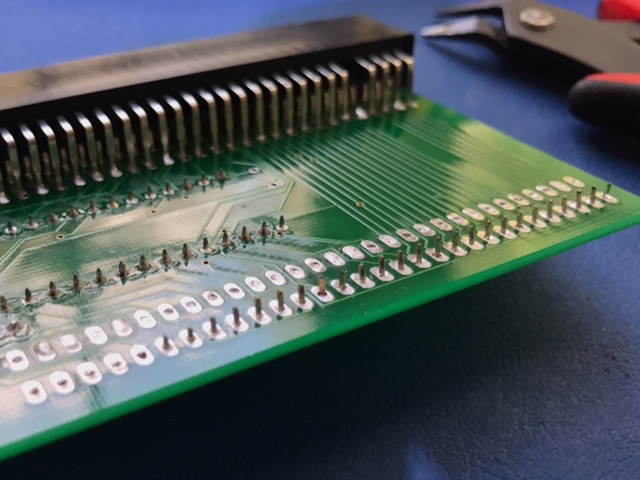
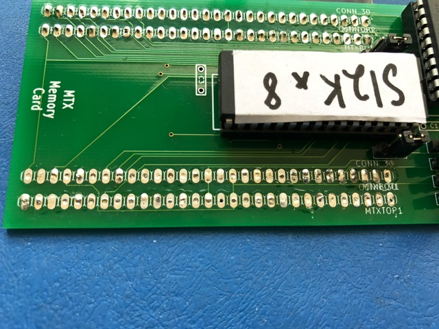
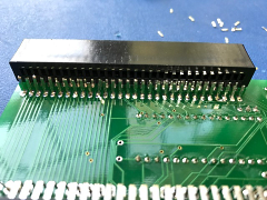
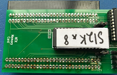
All pins
removed.
Next job was to clean up the solder
holes so that the new connector pins can be installed. |
 |
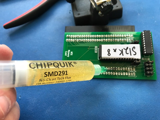
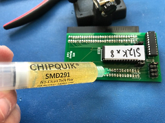
| I placed a
small bead of flux on each of the filled holes as it
helps in the removal of the excess solder. |
 |
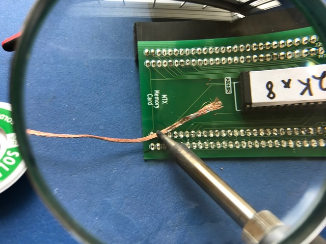
Using a
solder wick, I went over each hole in turn.
The
wick acts like a sponge soaking up the excess solder and
clearing the hole |
 |
| With all
the solder removed, the board was almost ready for the
new connector, but the burnt flux had to be removed
first using isopropyl alcohol, available from most good
chemists. |
 |
Looking
good!
(Ed. Good as new in fact -well done David) |
 |
| The 64 pin
DIN connector has 4 extra pins that need to be removed
and after checking, double checking and triple checking
that the right ones were selected, they were cut off. |
 |
| All four
pins removed. |
 |
| This
procedure was mirrored for the other connector, once
again, checking , double checking and triple checking
the correct ones were selected as I didn't have spares
if a mistake was made. |
 |
| Four pins
removed from the other connector. |
 |
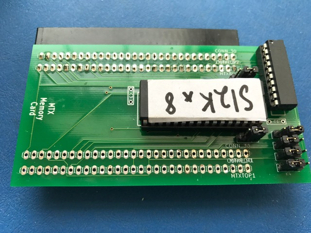
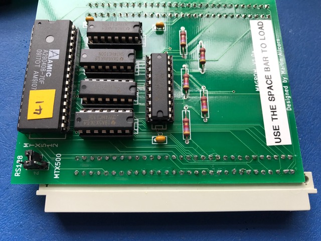
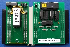
New
connector soldered into place. |
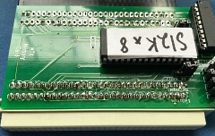 |
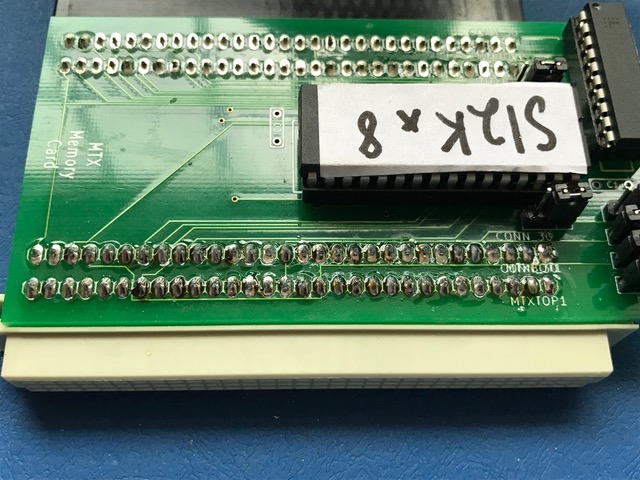
As with
Dave's modification, three patches R0 to R2 had to be
soldered between the edge connectors.
Also,
during testing it was found that another patch between
pins 30, the GROM, was also required. |
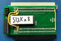 |
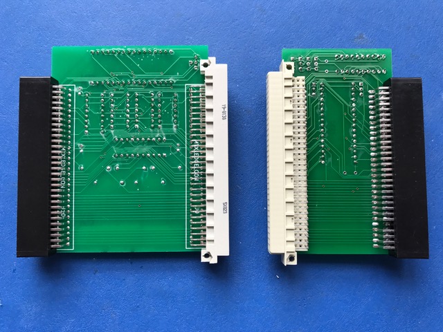
| The second
edge connector soldered into place onto the MAGROM. |
 |
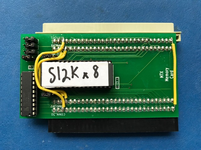
| Underside
of the two boards. |
 |
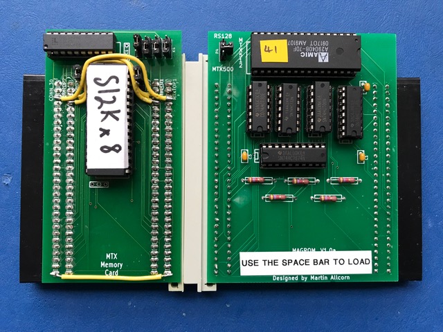
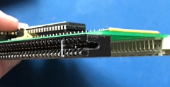
| Connected
together....... |
 |
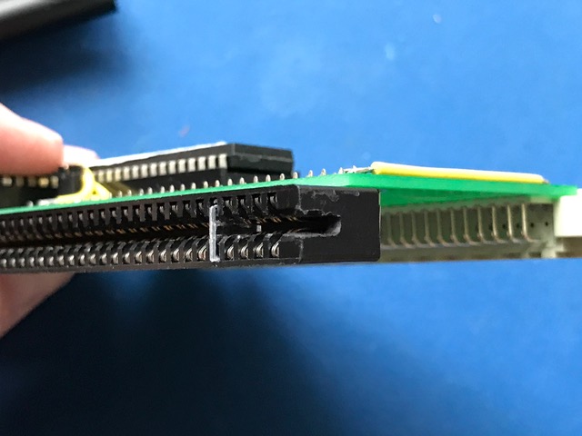
It's worth
noting that the edge connector needs slots cut out from
each end to make it fit over the board on the inside.
(Ed. with the slots cut, it is important that
the slot key in position 5 is present to prevent
misalignment when fitting the board !) |
 |
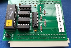
| ...... and
fitted neatly inside the MTX500. |
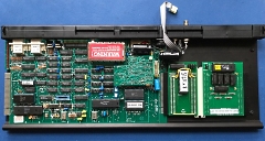 |
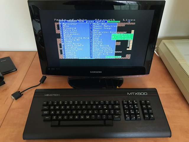
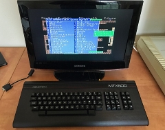
| Up and
running! |
 |