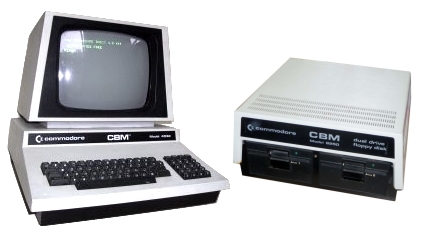
When petSD+ is powered on or reset, it will display the
current firmware revision for a few seconds, before
switching to the normal status display. petSD+ is
available for use immediately, the timed display of the
opening screen does not interfere with normal operation,
the device is available for immediate use from the PET
or pressing one of the option buttons will invoke the
LCD menu.
Diagnostic
Display (Offline)
(Requires
firmware dated 01-08-2015 or later) |
|
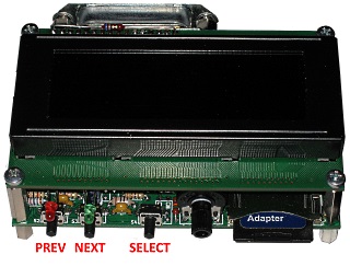
Holding in the Prev[ious]
button while powering on or resetting petSD+ will
bring up a hardware diagnostic screen as shown.
|
In this mode, petSD+ is
isolated from the IEEE-488 bus and will not respond
to commands from the PET.
The Red and Green LEDs will flash alternately
whilst in this mode.
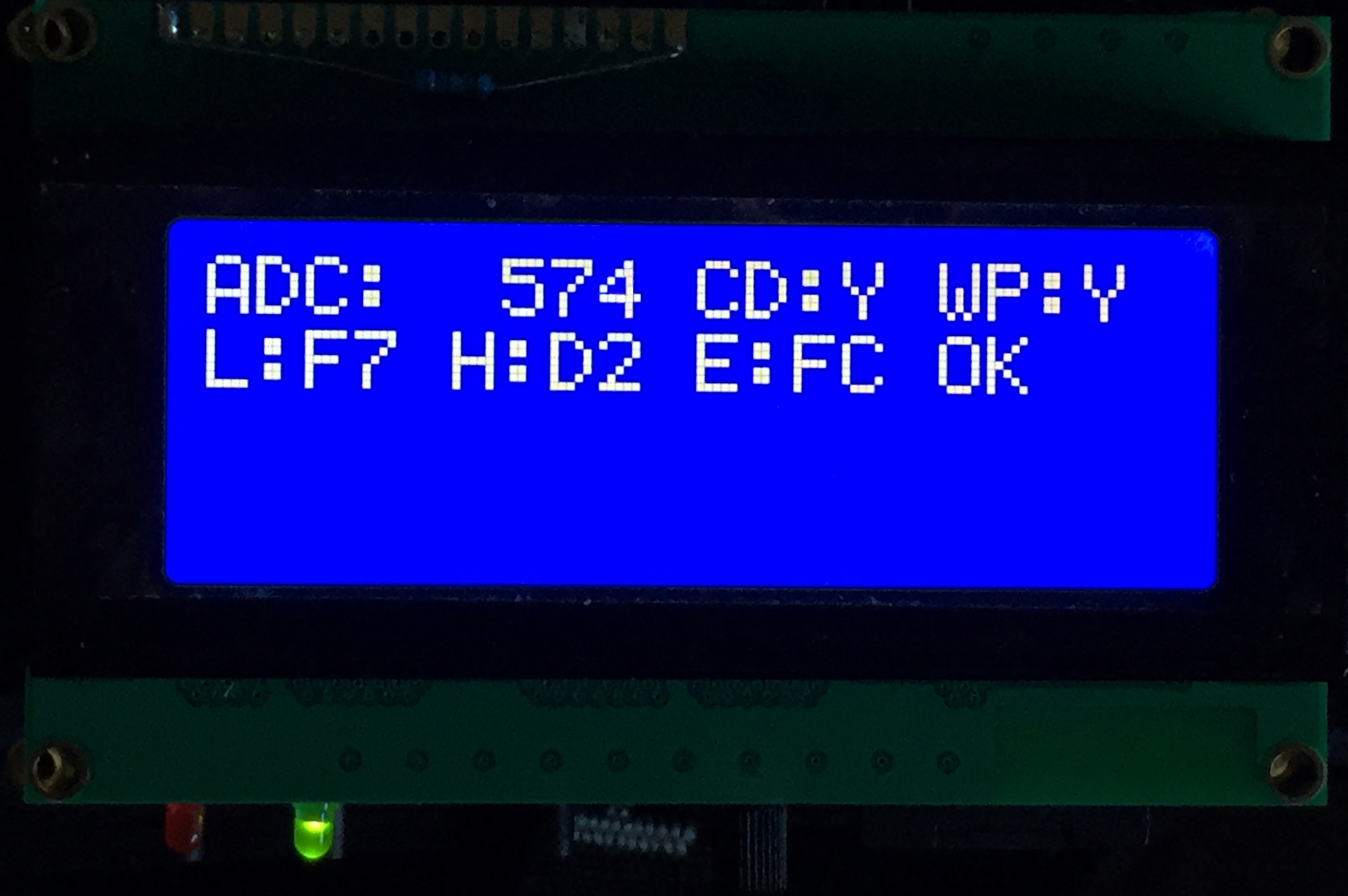
The ADC number is the value
read from the analogue to digital converter
connected to the Prev[ious],
Next and
Select control buttons. |
 |
As well as their
primary functions, the buttons, when used in
combination, can also perform additional functions
programmed in the firmware.
The table
shows typical values read / displayed for all
combinations of the buttons.
The other
fields are the status of the SD slot Card Detect and
Write protect switches and the values of the MCU
fuse words - "OK" signifying that they set as
required.
To exit diagnostic mode, power
cycle or reset petSD+. |
| Prev |
Next |
Select |
ADC |
| 0 |
0 |
0 |
573 |
| 0 |
0 |
1 |
774 |
| 0 |
1 |
0 |
655 |
| 0 |
1 |
1 |
931 |
| 1 |
0 |
0 |
607 |
| 1 |
0 |
1 |
838 |
| 1 |
1 |
0 |
700 |
| 1 |
1 |
1 |
1023 |
|
| |
|
Run-time LCD
Functions
(Requires
firmware dated 26-10-2015 or later) |
|
| |
|
The Prev
and Next buttons have
different effects depending on the context of their
use in the Menu system, the buttons are either used
to move between options ("tab" mode) or to adjust
the value within the selected option ("scroll"
mode), the Green LED is used to indicate the current
button mode; "tab" = LED OFF, "scroll" = LED ON.
When moving between menu options, or between
fields on an individual menu screen, the Green LED
is turned off. When the user wants to select a
particular configuration item for modification, the
user moves ("tabs") to the desired item and hits the
Select button. The Green
LED turns on and the Prev
and Next buttons are now
used to scroll through the available options or
values. When the appropriate value is highlighted,
pressing Select will save
the chosen value and the menu will return to "tab"
mode. At this point, the revised option has been
stored in memory only and is not permanently saved
until a Save Settings is
performed (see below). |
| |
|
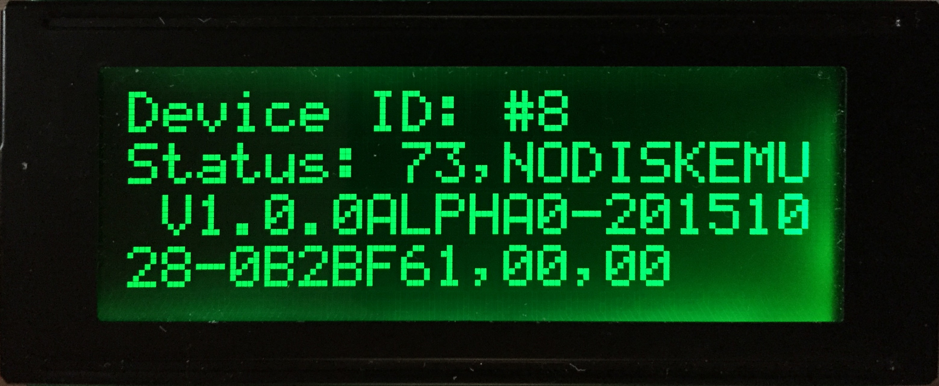
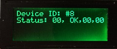
| If the user does not
interrupt the "Welcome" display, once it times out,
the LCD will show the device address and its current
status in a similar format as that returned from a
"real" Commodore disk drive running the Commodore
Disk Operating System (DOS) as shown on
page 1 of this guide. |
 |
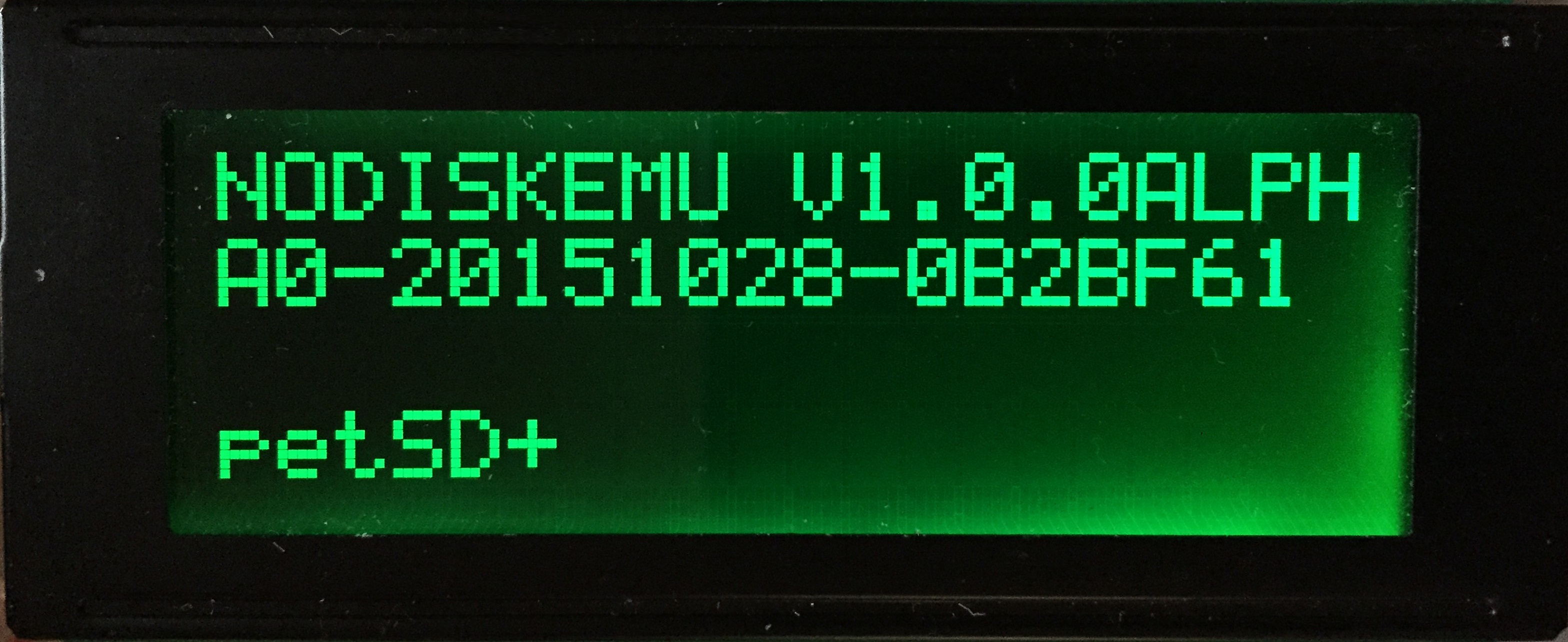
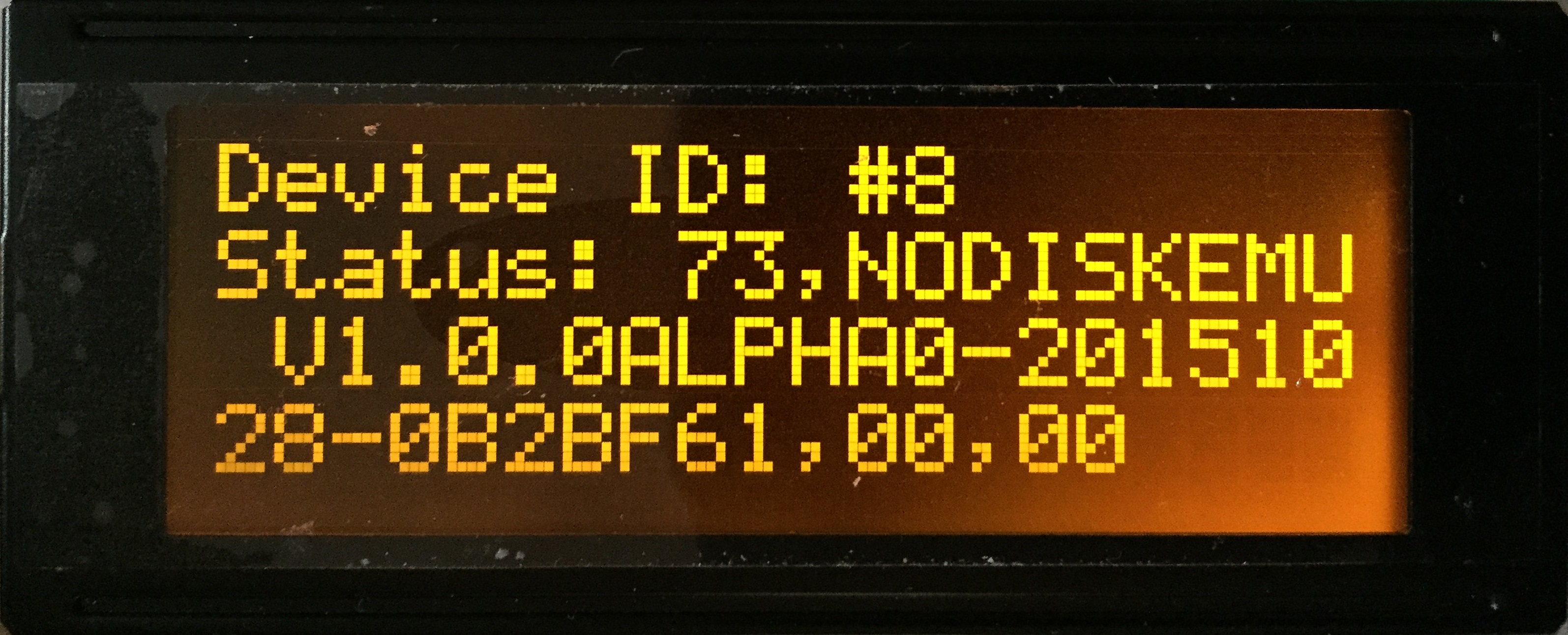
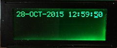
| An example of the Amber
LCD, the display is much better than it looks - the
photo is not helped by the fact that the display
still has its protective plastic film in place. |
 |
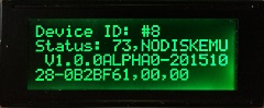
| After the system has been
initialised, display will report the status of any
future "disk" commands targeted at the petSD+ device
address in a similar way to Commodore DOS returns
status messages to the host. In this example, the
disk command was successful and its status was
reported as OK with zero
values in the status code fields. |
 |
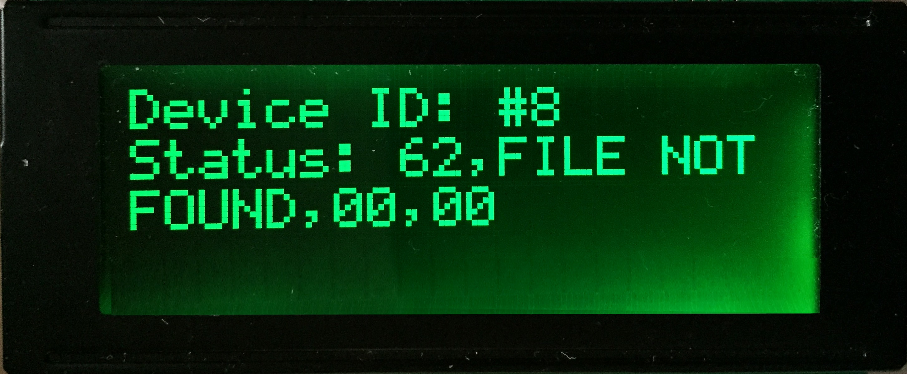
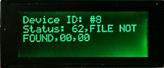
| If the command returns an
error, the LCD will display the relevant CBM DOS
error string and status codes and the Red LED will
flash. The error state will clear when a successful
command is entered at the PET and can also be
cleared by pressing the Prev
button, locate below the LED. |
 |
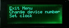
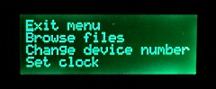
When petSD+ is operating normally,
pressing any of the Prev[ious],
Next and
Select control buttons will invoke the
LCD menu system.
While the LCD menu system is in
operation, petSD+ is disconnected from the IEEE-488
bus and the Red LED will be illuminated to show the
disconnected status. |
 |
When petSD+ is
disconnected from the IEEE-488 bus, commands issued
to it from the PET will generate a "?DEVICE
NOT PRESENT " error, when the LCD menu
system is exited, the device will again be available for
use from the PET. |
| |
|
Save Settings
Dialog
(Requires
firmware dated 26-10-2015 or later) |
|
| |
|
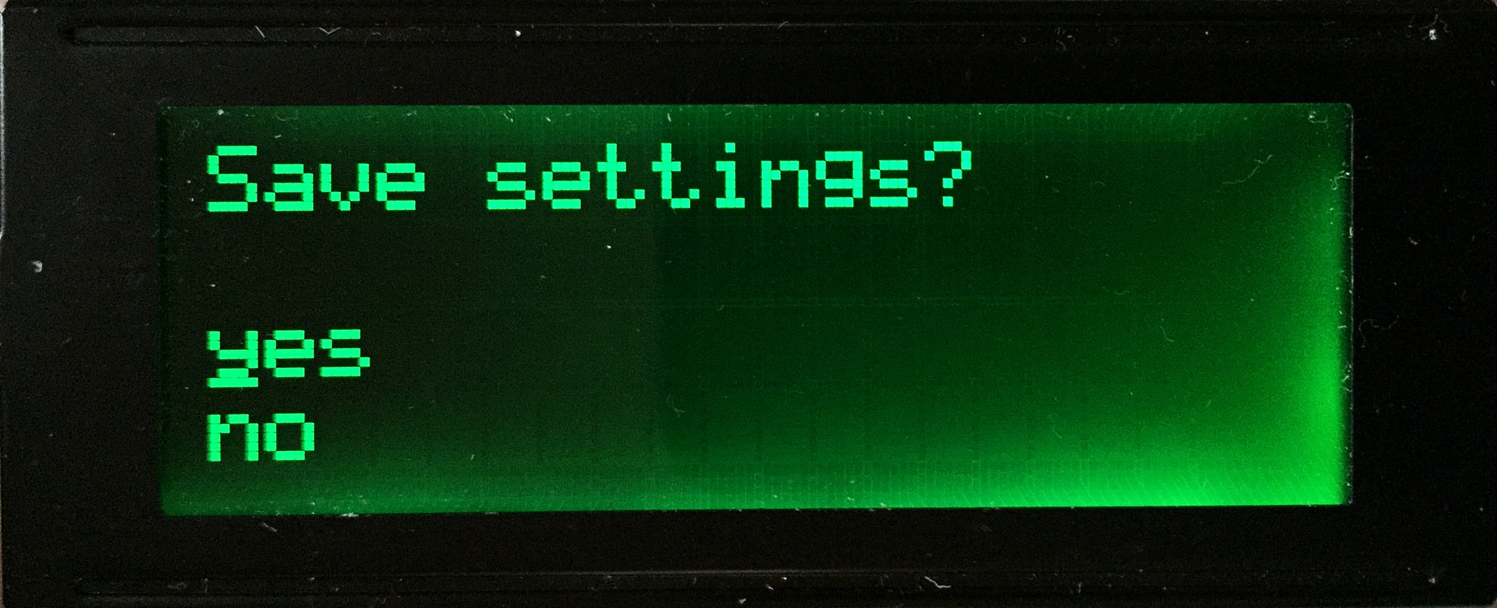
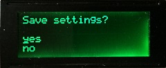
When the user changes
settings, such as the Device ID, they are given the
option to save the changes to the non-volatile
EEPROM area, if
the settings are not saved, they will be reset to
the stored configuration when petSD+ is reset or
powered off.
Note: when the
user elects to Save Settings,
ALL of the configurable settings are written to the
EEPROM - it is not possible to save only individual
configuration items. |
 |
| |
|
Change Device ID Number
(Requires
firmware dated 26-10-2015 or later) |
|
| |
|
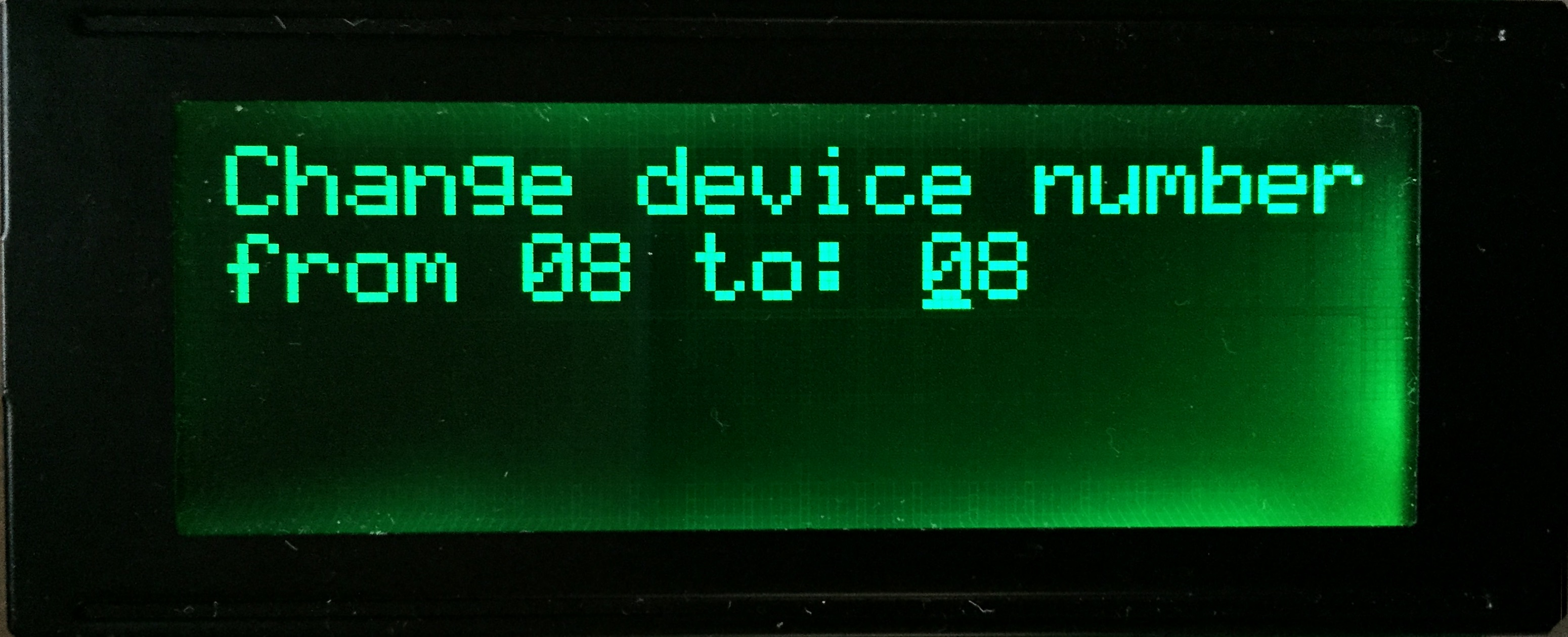
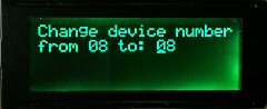
Selecting the
Change Device Number option displays
this screen.
Use the Prev
& Next buttons to cycle
through the legal value of 08 to 30, holding in the
button scrolls through at fast speed, use
Select to set the new ID.
(Use
Save Settings as desired.) |
 |
| |
|
Display and Adjust the Real Time Clock
(Requires
firmware dated 28-10-2015 or later) |
|
| |
|
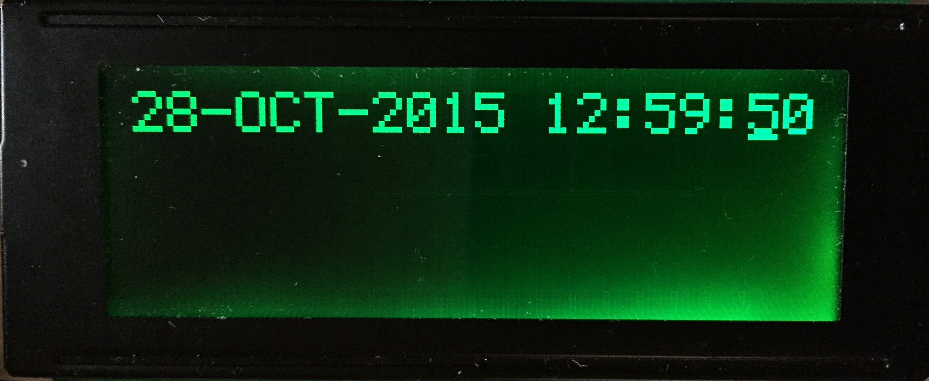
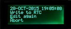
Selecting the
Set Clock option displays
this screen.
The cursor is initially placed at
the Day field, use the Prev
& Next buttons to
cycle through days 01 to 31, use
Select to accept the day and move
onto the Month field and
so on. The system is leap year aware, selecting
dates such as 29th February in a non-leap year, or
31st June in any year will jump back to the
Day field for correction. |
 |
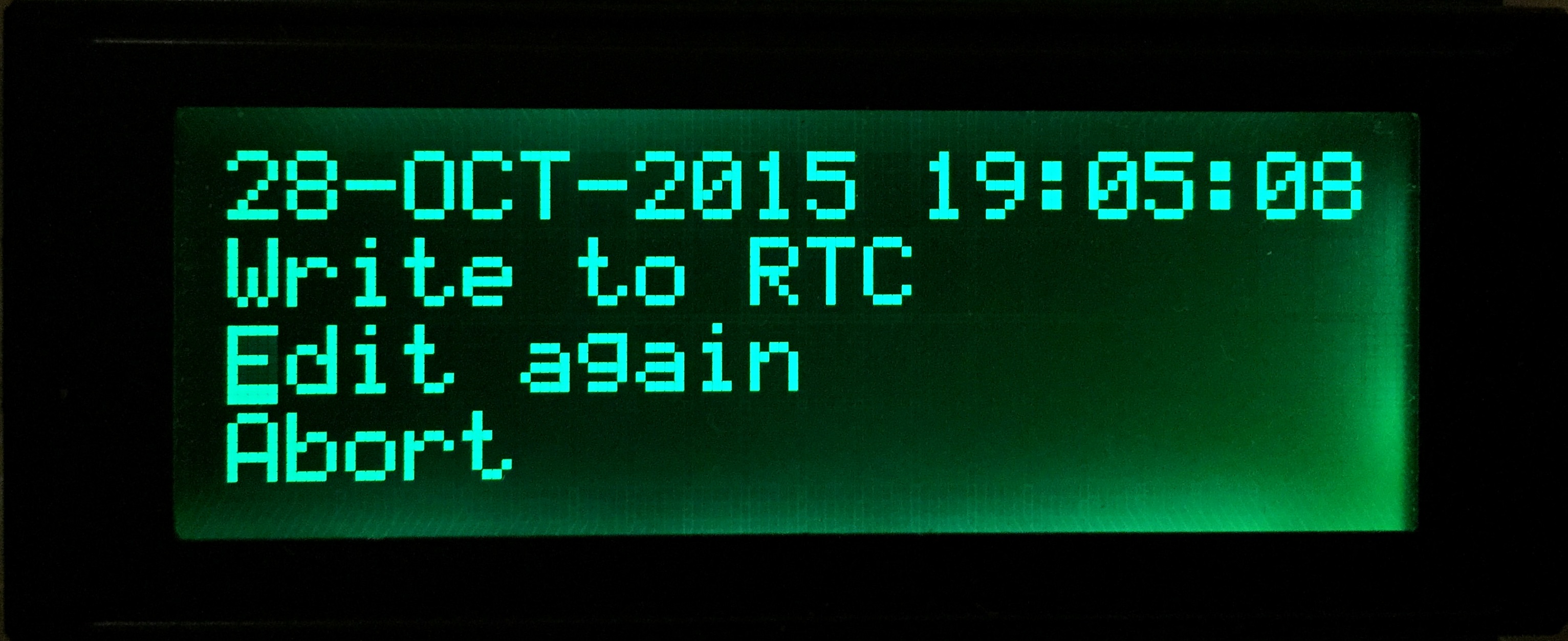
| Pressing
Select when on the
Seconds field will expose the
options to : |
| Write to
RTC |
Update the RTC chip |
| Edit
again |
Return to the clock edit line |
| Abort |
Quit without saving |
|
 |
Display and Change
Current Directory / Image File
(Requires
firmware dated 06-01-2016 or later) |
|
|
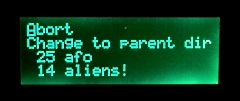
The Browse files option
now allows you to browse the SD card, change
directories and load image files using the
Prev, Next
and Select buttons |
 |
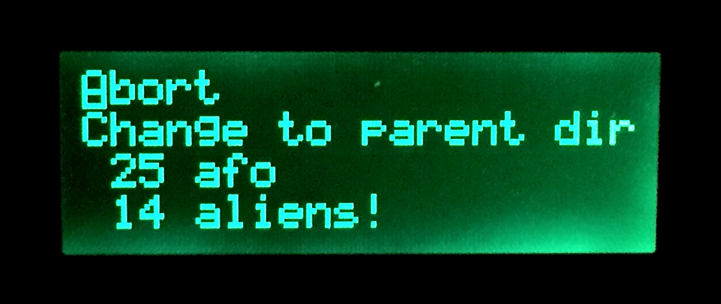
The Browse files option :
Abort
leaves the Browse menu
Change to parent Dir moves up a level
in the directory tree
The
Prev and Next
buttons scroll the directory list and and
Select changes to the
marked directory or image file. |
 |
|
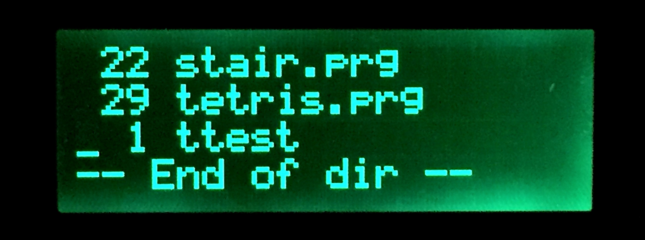
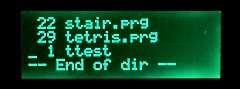
Browsing to the bottom of the current directory |
 |
Notes :
The current firmware does
not prevent you from trying to move above the top
level directory, no damage is done, but the device
reports a "Not Found" error.
As
described above, the LCD menu allows the user to
change directories and load image files by selecting
the appropriate entry in the directory listing. This
is made possible by NODISKEMU's ability to support
directories in the same way as CMD disk drives did -
that is, disk directories and image file support is
implemented in the device firmware. Commodore BASIC
is not aware of the directory structure, and BASIC
commands such as directory
just return a list of files that appear to the
system to be in the root directory of a floppy disk.
Whilst it would be ideal to be able to load
a program file using the Select
button on petSD+, this is currently not possible and
would require significant modification to petSD+ to
implement it. To perform an action on the PET, such
as initiating a file load, petSD+ would need to be
able to flag up a request for action to the
computer. Although the IEEE-488 standard includes an
interrupt line (SRQ = service request) and this line
is internally attached to the CBM/PET, the KERNAL
ignores it completely. It would be possible to patch
the KERNAL or add functionality to Steve Gray's
Editor ROM, to provide Operating System support for
remote file load requests, but the petSD+ MCU does
not have spare I/O to support the SRQ line. |
|
|
|
|
|
|
Toggle IEEE-488 / IEC Mode
(Requires firmware dated 15/03/2016 or
later) |
|
|
|
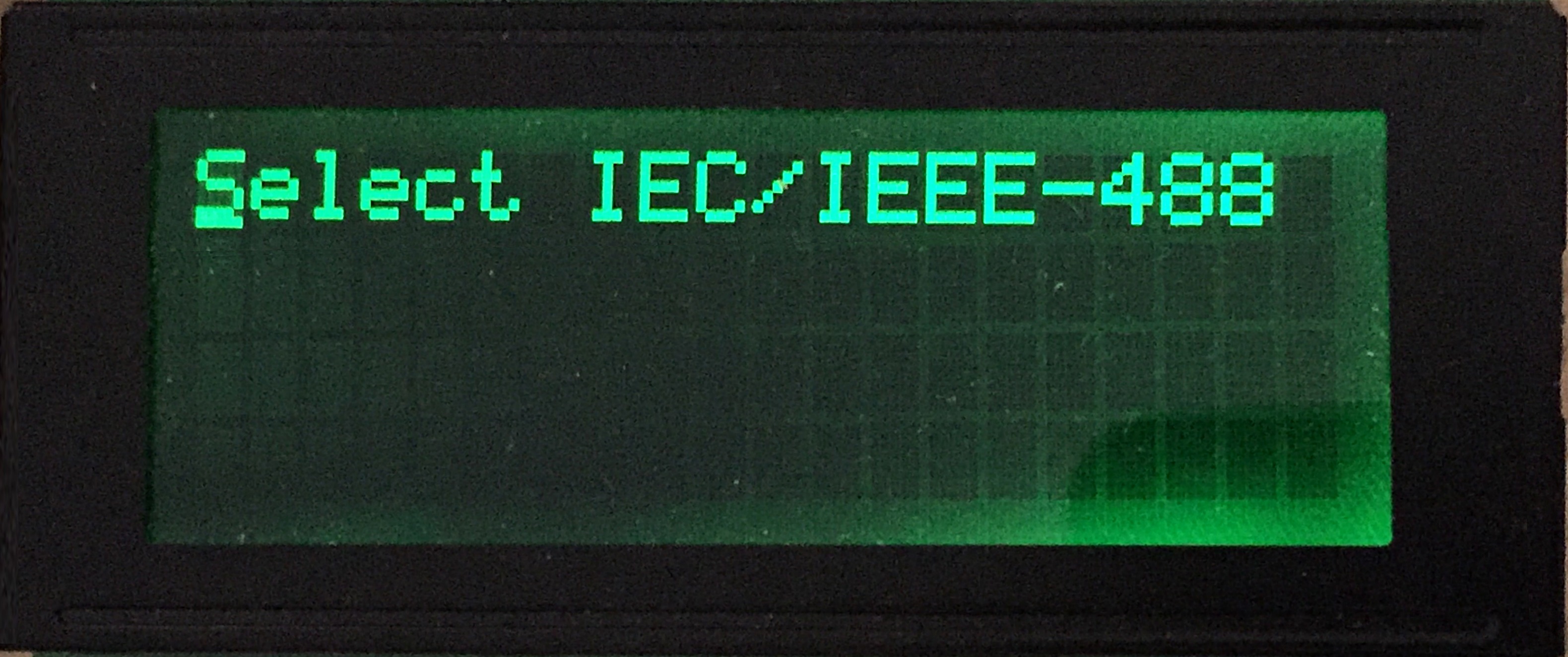
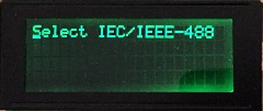
From the main menu, scroll down to the second page
of the menu until you see the
"Select IEC/IEEE-488"
option
Press Sel to
select that menu entry
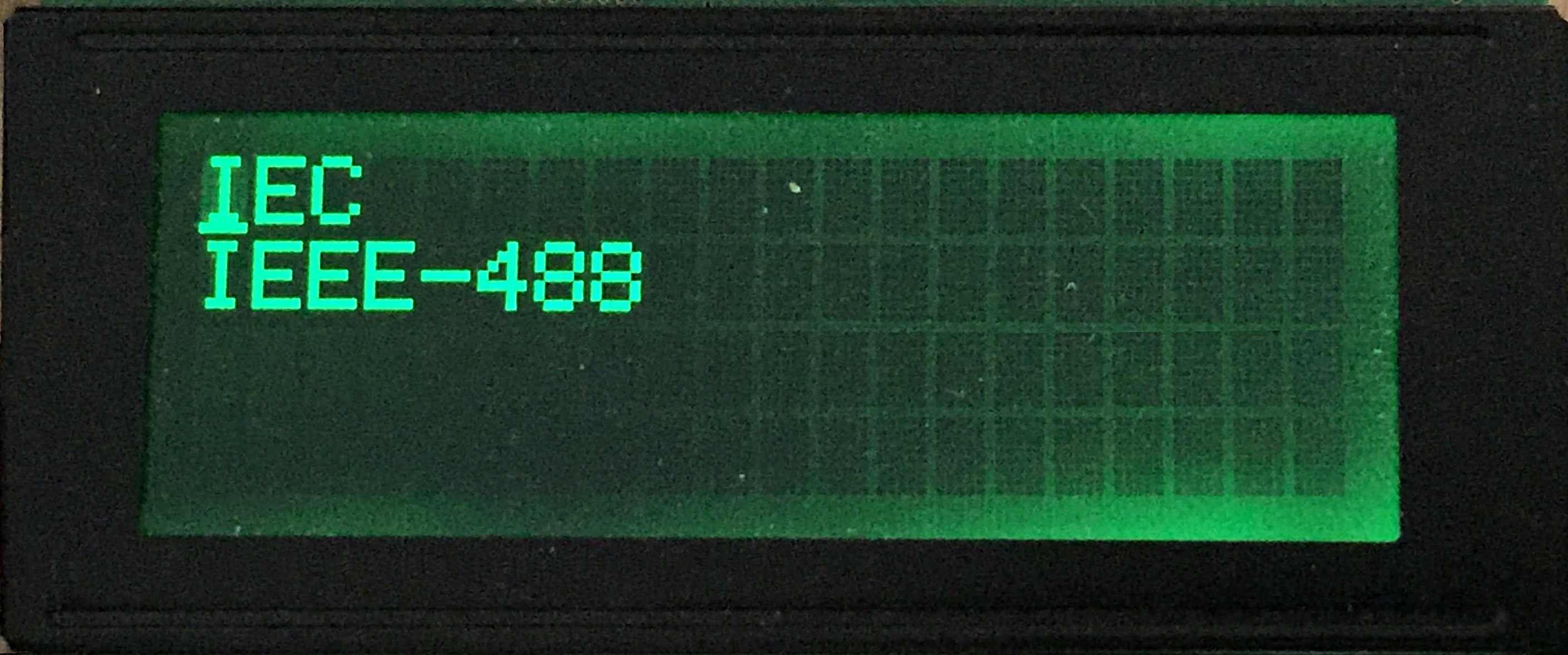
A submenu with the
two entries IEC / IEEE-488
will appear. |
 |
Position the cursor on the required option and press
Sel
"IEC" for serial
interfaces, e.g., the Commodore 64, or
"IEEE-488" for parallel
interfaces, i.e., Commodore PET |
 |
The Save Settings
dialogue will be displayed
Position the cursor on
the required option and press Sel
Selecting yes will
save the setting to Flash and will persist through
reset or power cycles |
|