|
 |
The Memotech MTX Series |
 |
MTX Pi
Andy Key's Memotech
emulator, MEMU,
is a fully featured emulator for the complete MTX range of
computers, including the disk drives and video hardware required
to run CP/M. MEMU runs on Windows and Linux, including, thanks
to Bill Brendling, the Rasbpian Linux distro for the
Raspberry
Pi.
Using MEMU on a PC or Raspberry Pi is fun, but the experience
is spoiled a little by having to use a modern day PC keyboard. I
wanted to try using a Raspberry Pi to run MEMU, but use a real
MTX keyboard to recreate the look and feel of a real MTX
computer.
Although I have a few MTX machines, all of them are working
and I did not want to break up a perfectly good system to
"borrow" the keyboard, even on a temporary basis. I had been on
the lookout for a broken, and preferably, irreparable, MTX for
some time that I could use for this project. I was not having
any luck until a MTX keyboard came up on ebay UK. Although I
ended up paying more than I wanted to, I bought the item with a
view to building MTX Pi.
The ebay keyboard consisted of the top half of an MTX 512
computer, it was missing the bottom half of the case, the end
plates and the plastic insert where the I/O ports are usually
mounted. However, I did have the other half of a MTX case that
Trevor had kindly given me in May 2014,
although it too was missing the port mounting insert and I did
not have any spare end plates that hold the two halves of the
MTX computer together. Jim Wills has donated the port mounting
panel from one of his old machines, so I have enough to get
started - the only missing items now are the end plates for the
case.
|
Proposed Feature List |
|
Interface |
Description |
Status |
|
Keyboard |
MTX512
keyboard for user input |
Done |
| |
USB PC
keyboard for programming/configuring Raspberry Pi |
(USB) |
|
Mouse |
USB PC
mouse for programming/configuring Raspberry Pi |
(USB) |
|
Joysticks |
2 x
Atari 9-Pin ports (optional) |
Done |
| |
1 x USB
PC joystick (optional) |
(USB) |
|
Audio |
3.5mm
Stereo output jack (replacing the MTX Phono Hi-Fi
output) |
Done |
| |
Via
HDMI port (optional) |
Done |
|
Video |
Composite Video output photo connector
(replacing the MTX BNC video output) |
Done |
| |
Via
HDMI port (optional) |
Done |
|
Serial |
(Future) |
(future) |
|
Network |
MTX
"Node" (future) |
(future) |
| |
Ethernet RJ45 (optional) |
Done |
|
Printer |
MTX
Centronics Printer (future - requires additional
interface board) |
(future) |
| |
Raspberry Pi Network printing (future) |
(future) |
|
USB |
3 x
Used - Keyboard, Mouse and Joystick |
Info |
| |
1 x
Spare |
Info |
|
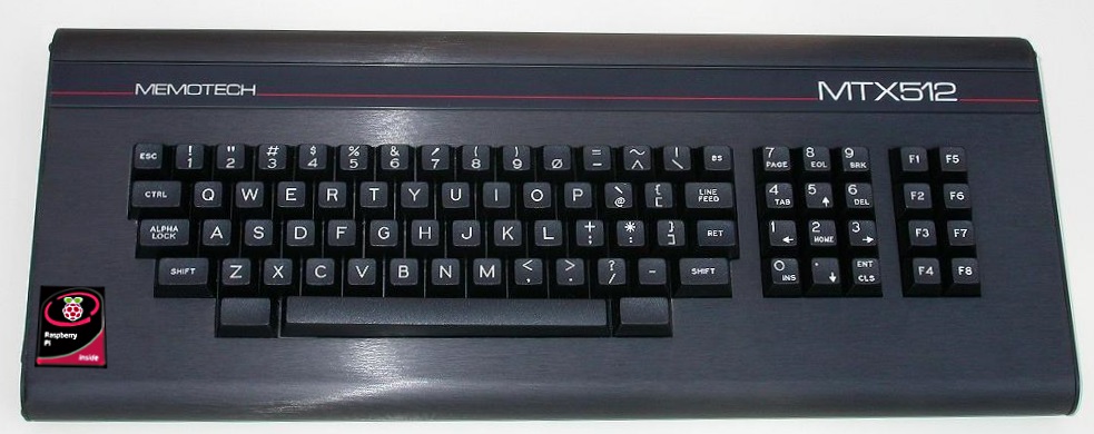
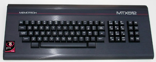
The Original |
| The Memotech MTX system board is installed in a
brushed aluminium case, with a full travel, 79 key,
keyboard mounted in the upper half of the shell. The
keyboard includes a separate numeric keypad, 8
function keypad and two blank keys, either side of
the spacebar, which, when pressed simultaneously,
reset the computer. |
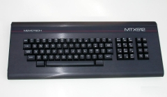 |
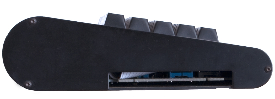
| The view from the left hand
side of the MTX, showing the cartridge port and the
profile of the case. The case is held together by
3x3mm Allen bolts through the plates at each end. |
 |
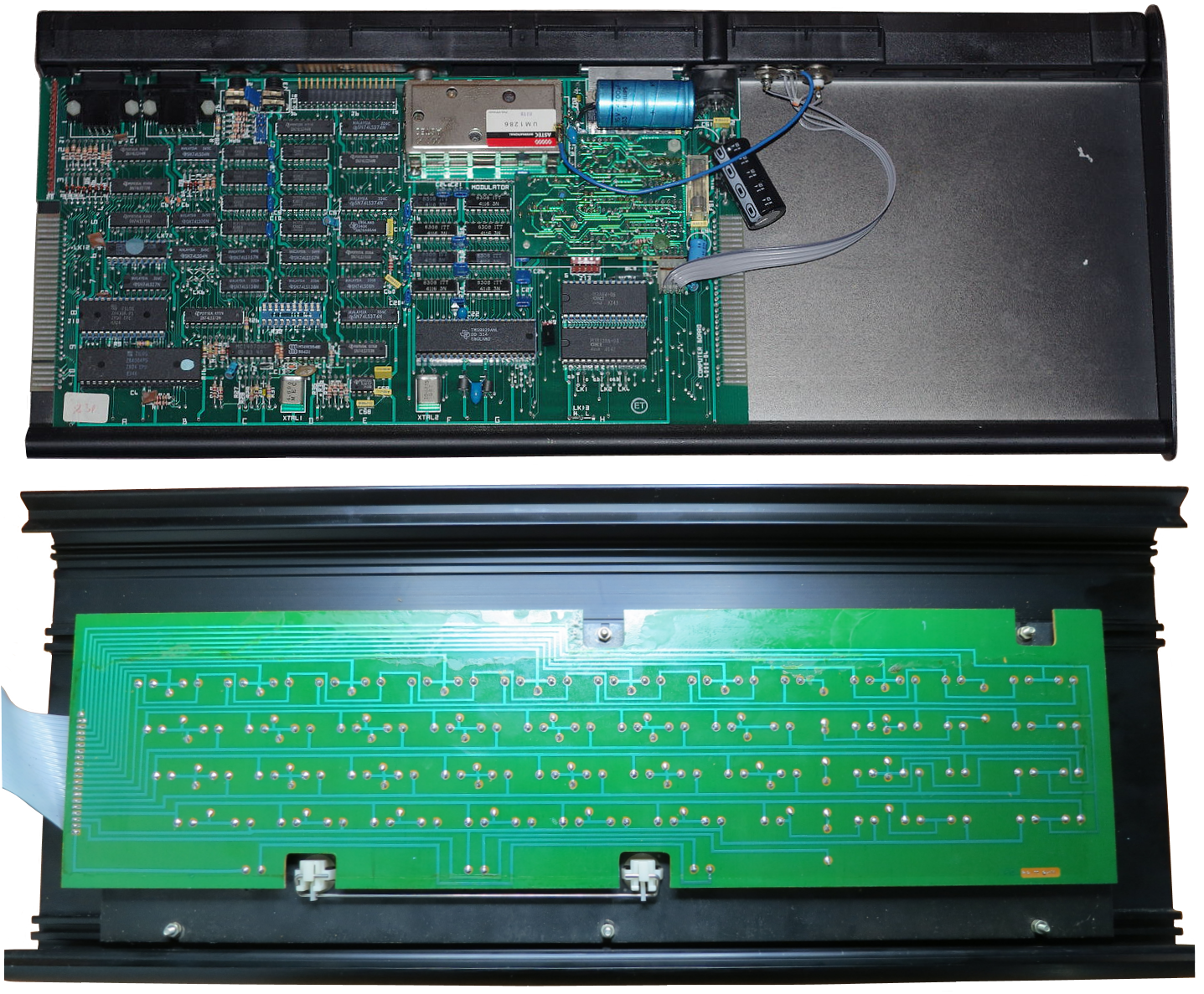
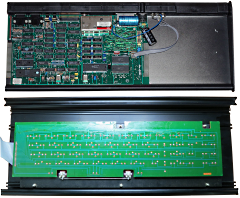
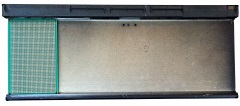
The two halves of the
disassembled MTX case.
The MTX computer board
is secured with a single screw through the base and
the heat-sink (hidden by the large capacitor next to
the silver UHF modulator).
The rear of the
MTX is a plastic molding that slides into a groove
in the base and is used to mount the I/O and power
connectors.
The keyboard base plate is bolted
to the underside of the upper half of the shell, the
grey cable at the left normally connects to the pin
header in the upper left corner of the MTX computer
board. |
 |
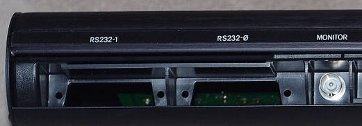
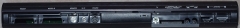
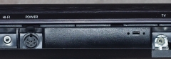
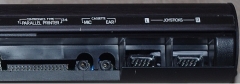
| Photos showing rear panel's I/O ports
and connectors, from left to right . . . . .
Cut-outs for two serial ports, RS232-1 and
RS232-0 , these were optional extras, the ribbon cable
for the FDX exited the case above these ports from the
same expansion board. MTXs without serial ports fitted
were fitted with covers over the port cut-outs (this MTX
has had an RS232 board removed).
Adjacent to them is the BNC connector for the
Composite Video monitor output.
Next are the Hi-Fi and power connectors. This
photo is of a US export model - the small slot was
for the TV channel selector switch fitted to US
models
On the right hand side are TV, parallel printer,
audio "mic" and "ear" connectors (used for
loading/saving software from tape) and two Atari type
joystick ports.
(Photos courtesy of John Halliwell) |
 |
 |
 |
 |
|
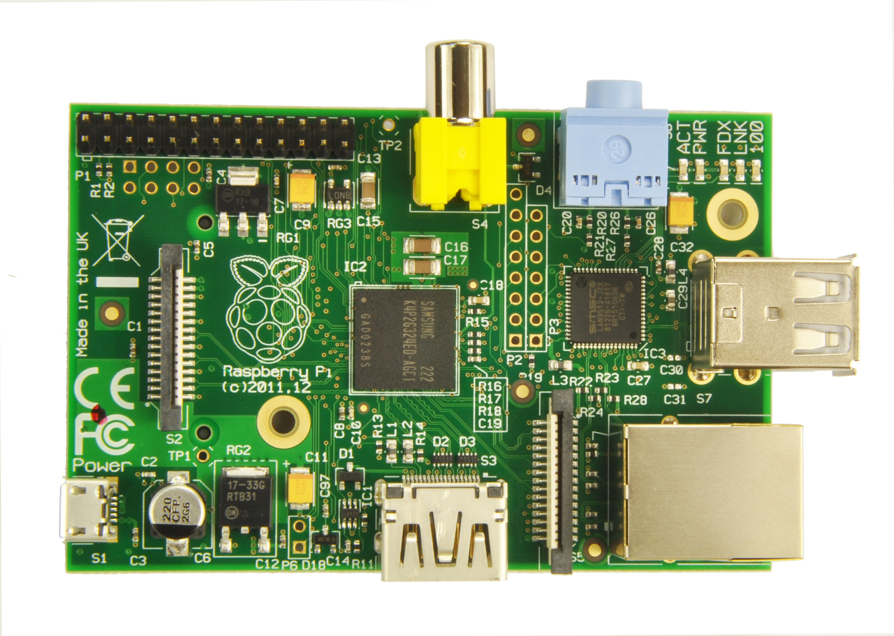
The Imposter |
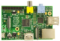
I have a number of Raspberry
Pi Model "B"s, including the original Revision 1
board (256MB) and Revision 2 (512MB).
These
boards have 2 x USB 2.0 ports and a 26-Pin GPIO
connector with 17 available I/O pins, a further 4
GPIO pins are available if a header is fitted to the
unpopulated pads on J5.
Though it would
probably do the job, I decided that having all of
the GPIO pins on a single header would be better so
I would not use the Revision 1 board. |
 |
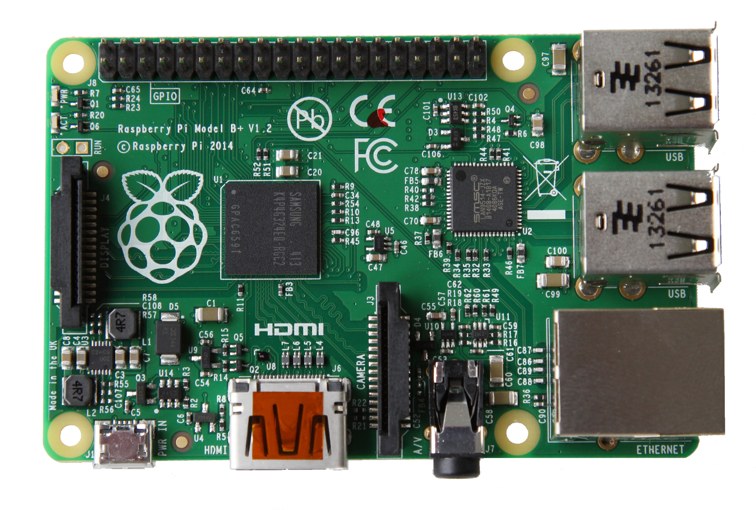
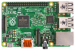
| The Model 1 "B+" board has 4
x USB 2.0 ports and an expanded 40-pin GPIO
connector with 26 GPIO pins available. |
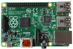 |
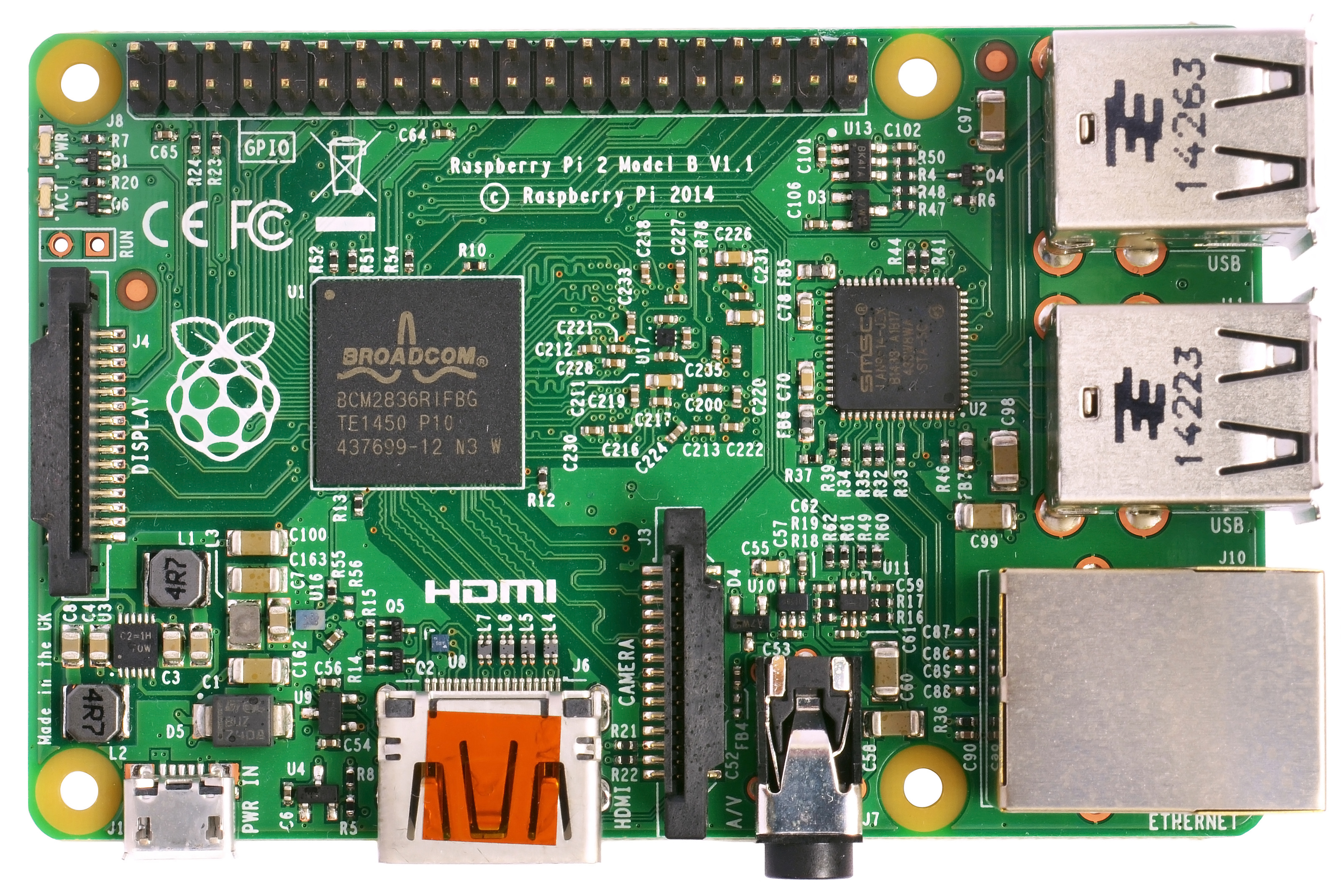
The Model 2B has the same USB and I/O capabilities
with an enhanced processor and more memory, but the
physical dimensions and port positions are the same.
The design will be based on using
a Model 1 "B+" (which I have), rather than
a Model 2B (which I don't). |
 |
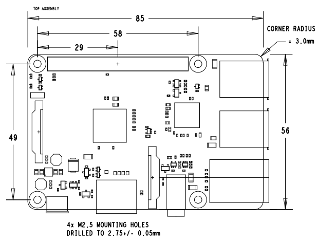
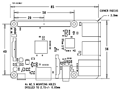
A simplified mechanical
drawing of the Pi Model B+ and Model 2B.
Having dimensions of 85mm x 56mm, the Pi board will
obviously
fit inside an empty MTX case, but the board is small
enough that it could also fit inside an MTX with the
system board and up to 1 expansion board already
present.
Given the low profile of the MTC
case and limited clearance below the keyboard, the
more critical dimension is the height of the RPi
board, for the Model 1 B+, this is ~21mm from the
top of the USB connector to the bottom of the
micro SD card. |
 |
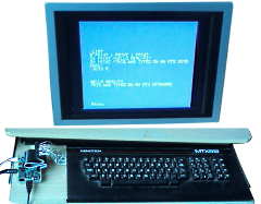
| Bill Brendling's Raspberry
Pi connected to an MTX keyboard during the software
development phase |
 |
|
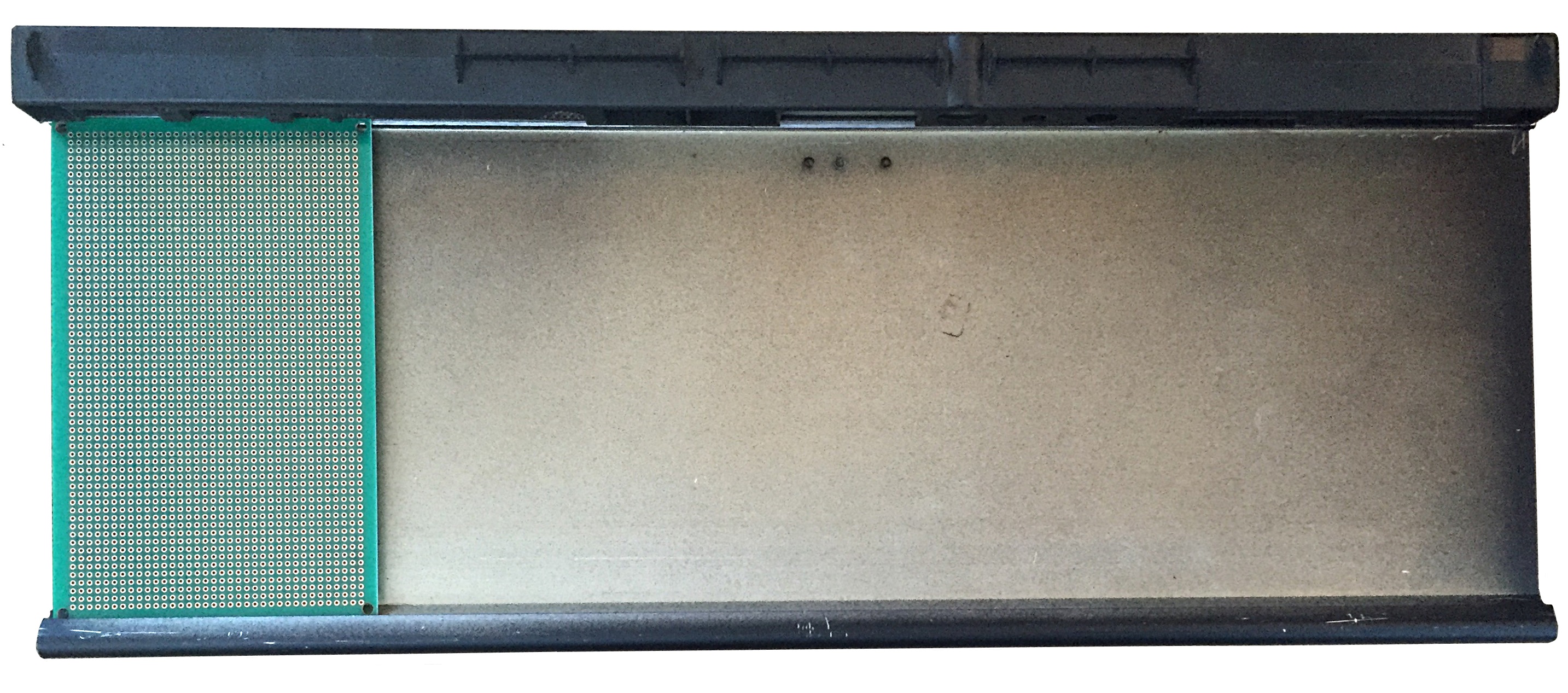
Preparing the MTX Case |
Since the MTX "Atari" type
joystick ports are just connected to the keyboard
drive & sense lines, I shall be adding joystick
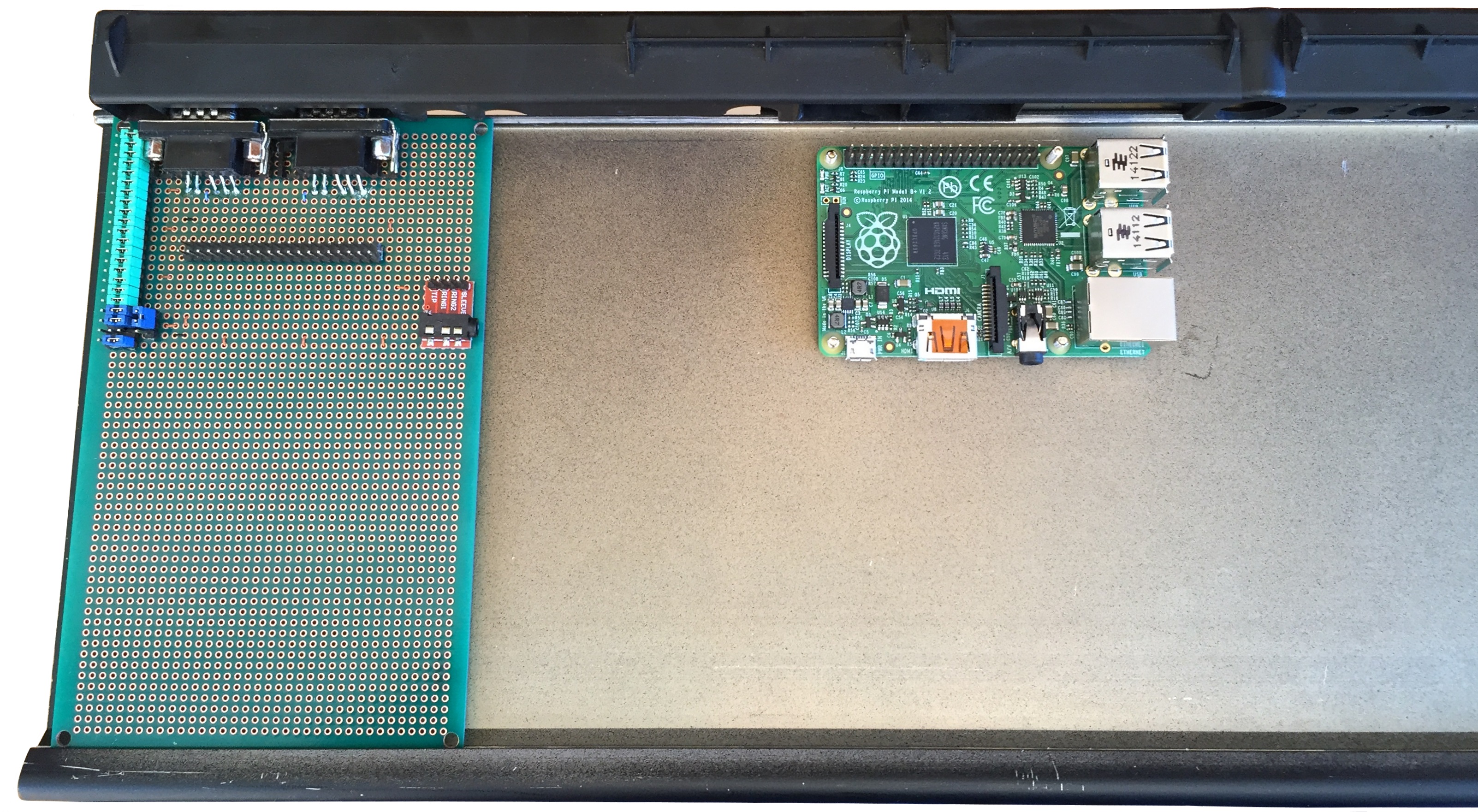
ports to the system.
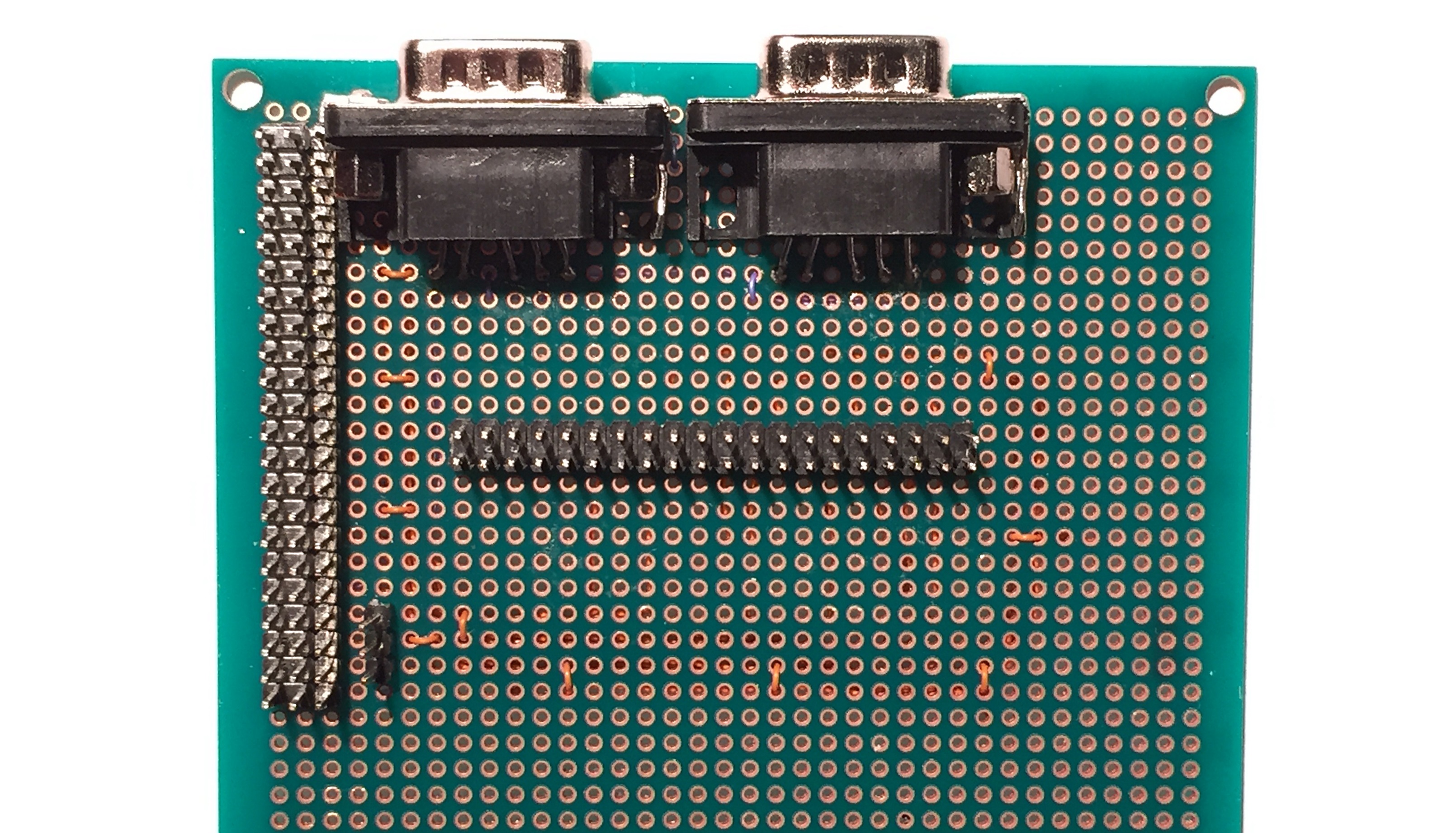
A
Eurocard size prototype board fits the MTX PCB
guide slots perfectly and will be used to mount
9-way "D" type connectors for the joysticks. |
 |
The "D" connectors soldered
to the prototype board.
The pitch of the
connectors does not match the 0.1" of the proto
board, but with a little persuasion, they could be
bent to fit without stressing the pins too much.
The screw sockets have been reversed to allow
the connectors to be mounted flush with the molding,
the joysticks won't use them, but they are also used
to secure the metal "D" shell cut-out. |
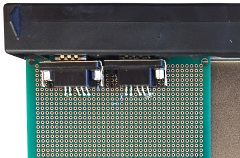 |
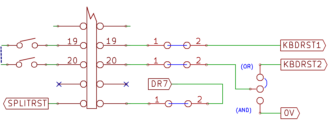
| The MTX keyboard has two
unmarked keys, either side of the spacebar, that are
used to reset the MTX. They are hard-wired in series to
the Z80 Reset circuit but will be repurposed in MTX
Pi to provide two, independent, MEMU control keys, by
patching one of the keyboard drive lines between the
reset keys and taking the return lines to two GPIO
inputs. |
 |
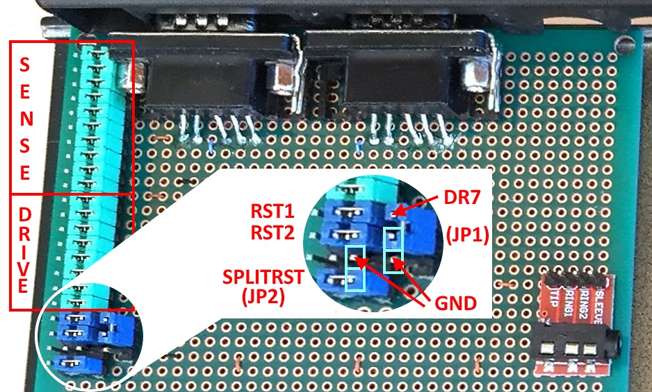
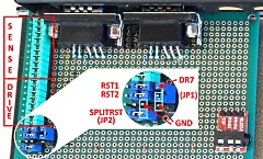
| To provide the flexibility
to easily convert back to the standard MTX
configuration, jumpers are used to disconnect the
additional drive line and reconnect the reset key
return to ground. |
 |
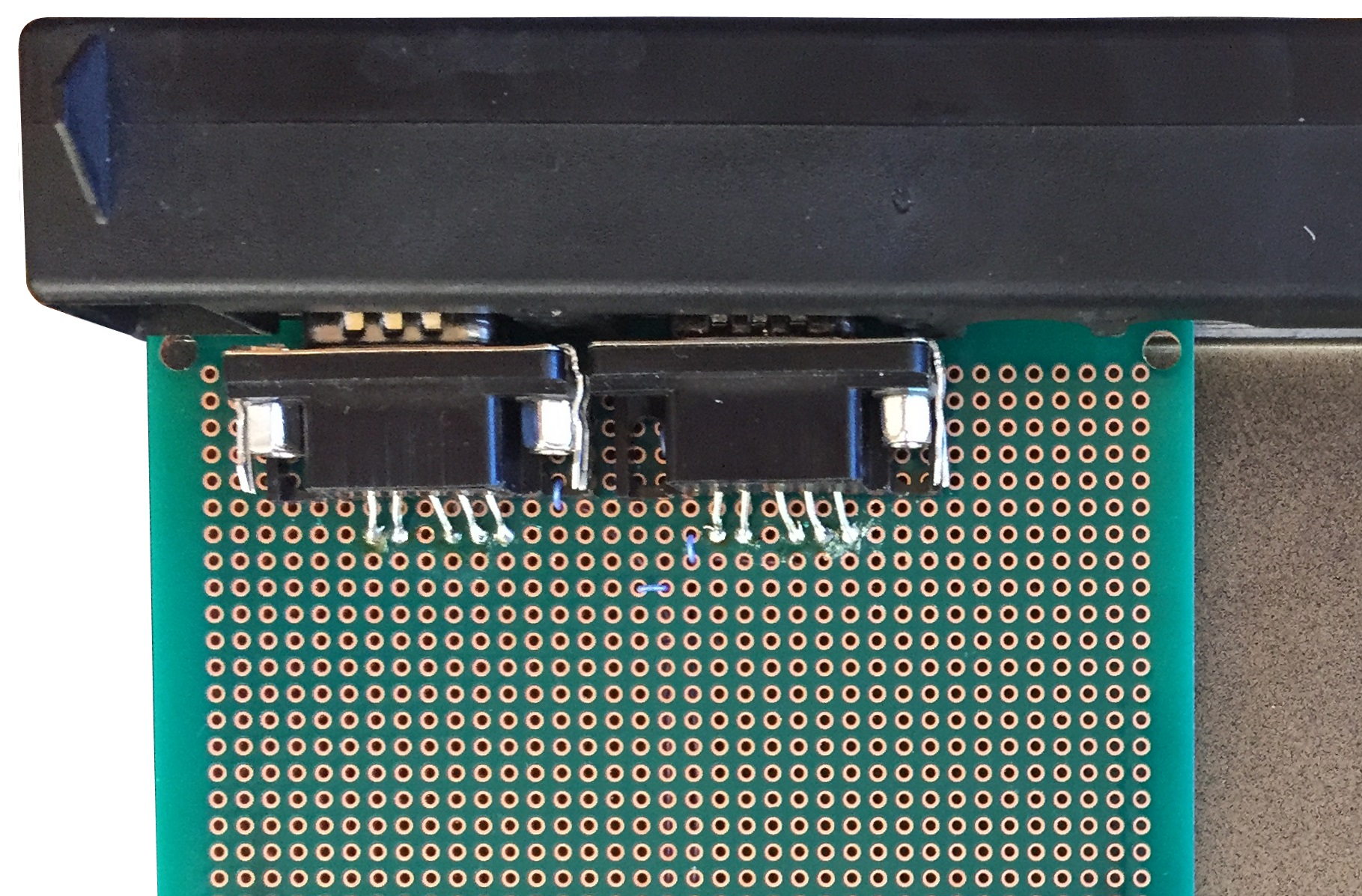
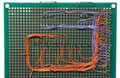
The board will also be used
for the MTX keyboard header, a 40-pin IDC header
that will be cabled to the Pi GPIO header and the
patch wiring between the headers.
The columns
of header pins at the left are for the keyboard
connector and the 40-pin header in the centre of the
board is for the Pi GPIO cable. |
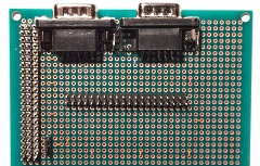 |
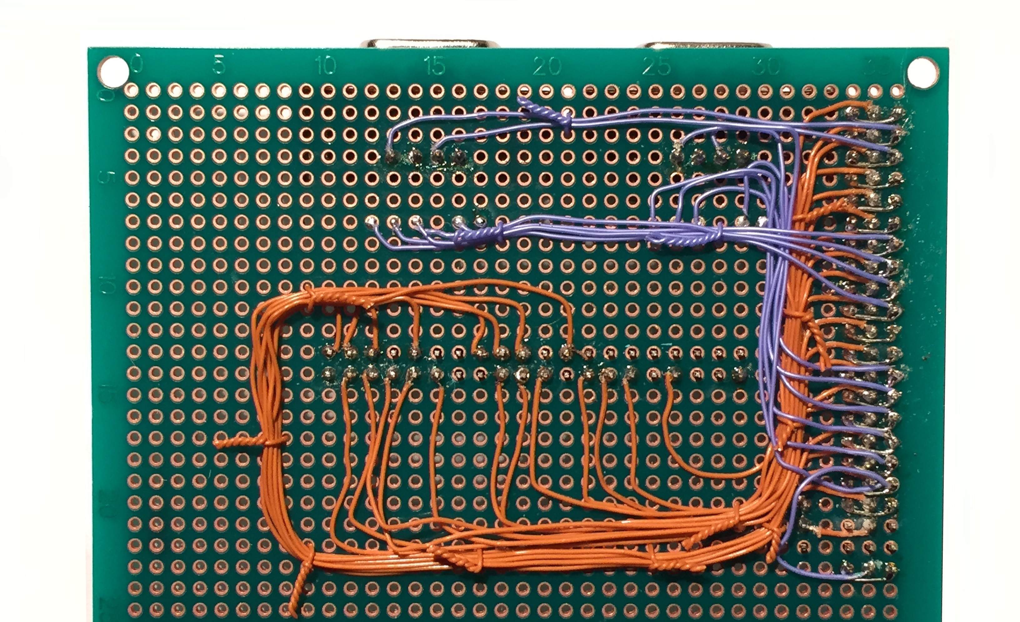
The patch wiring maps the
MTX keyboard lines to the Pi GPIO header, the I/O
pins were allocated before the start of the build
and should not need to be changed.
Although
it was not necessary, to provide maximum
flexibility, the keyboard headers allow the wiring
between the keyboard lines and the GPIO header to be
re-patched as required. |
 |
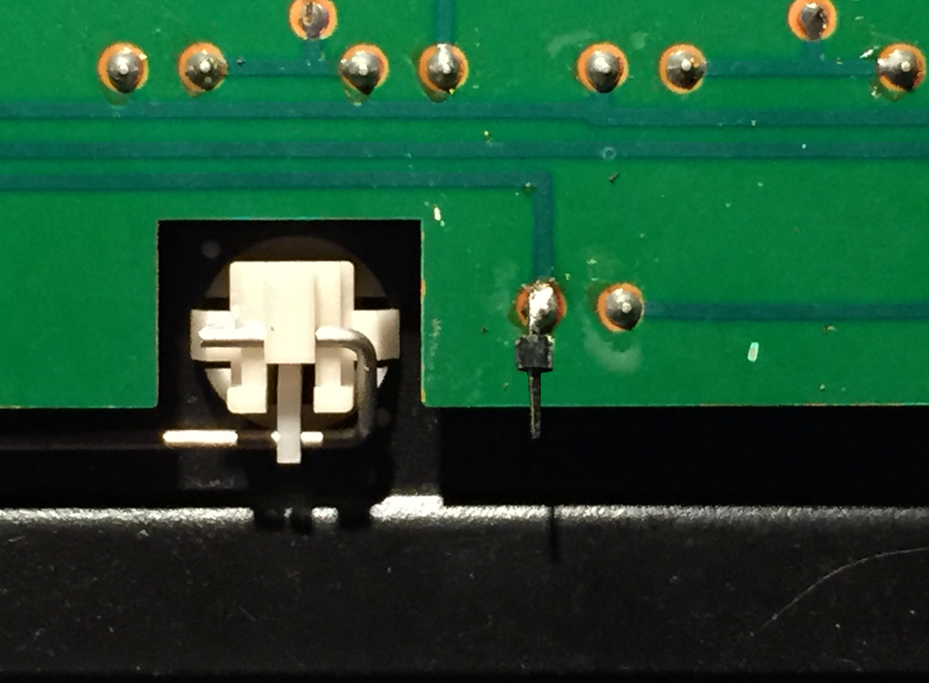
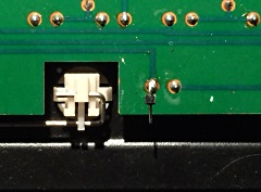
| To allow one of the keyboard
drive lines to be connected between the reset keys
while keeping the changes to the keyboard PCB to a
minimum, I just soldered a single header pin onto
the inboard solder pad for one of the reset keys. |
 |
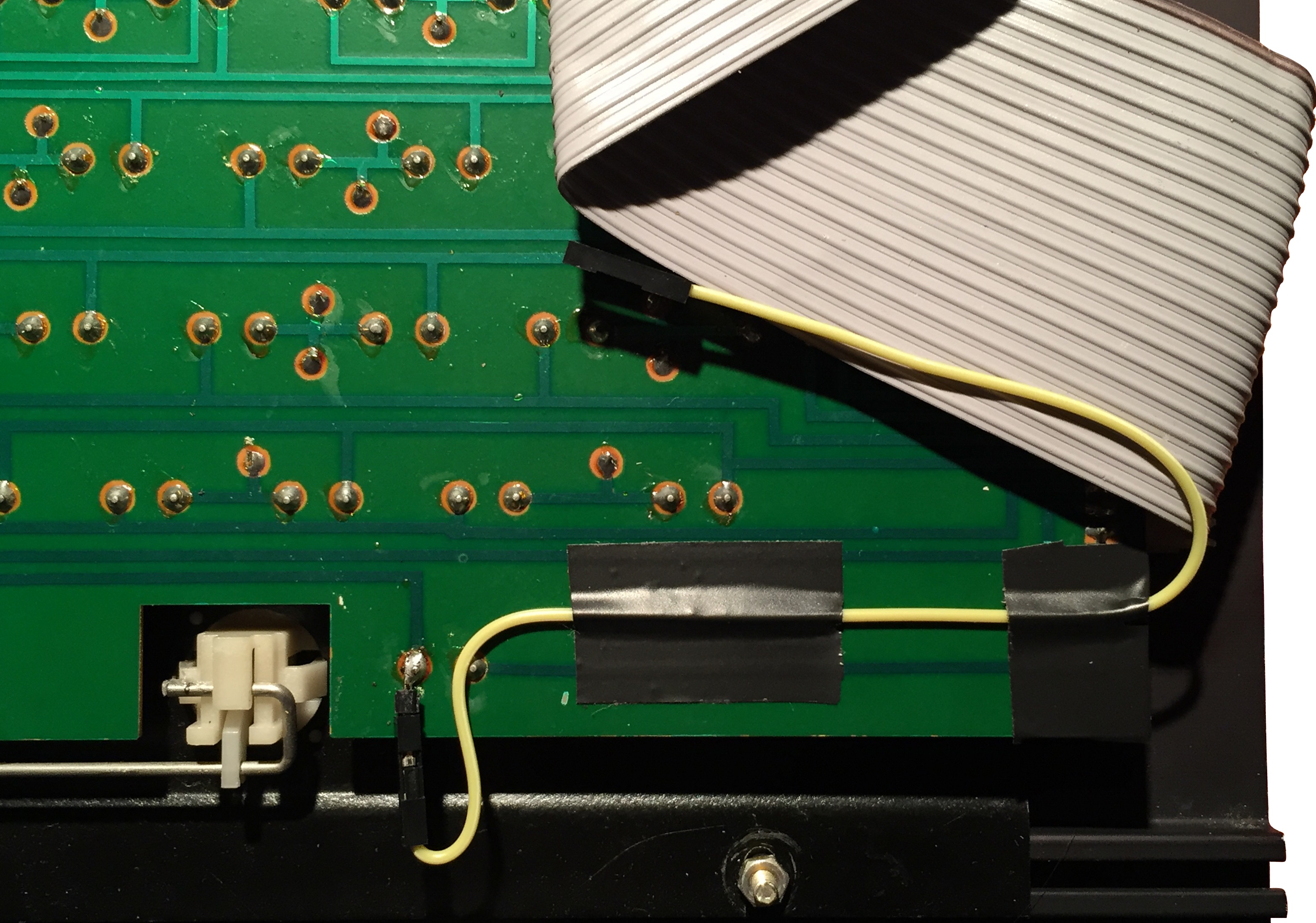
| Jumper cable connected to
the header with a Dupont connector |
 |
The Pi has ports and
connectors on all sides, I found that the best place
to position it was more or less in the mid position
of the base, with the GPIO connector at the rear as
shown.
Later models of the Pi, including the
Model 1 B+, have mounting holes in the PCB, but, as
might be expected, given the size of the board, they
are sized for M2.5 screws. |
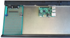 |
I had hoped to use
self-adhesive PCB mounts, but could not find ones
small enough for the Pi mounting holes. Instead, I
found that the MTX circuit board fixing hole was in
the perfect position to align with one corner of the
Pi PCB. With 1 screw through the base, the Pi was
adequately secured but I put screws in the other
three holes to make "feet" for the other corners.
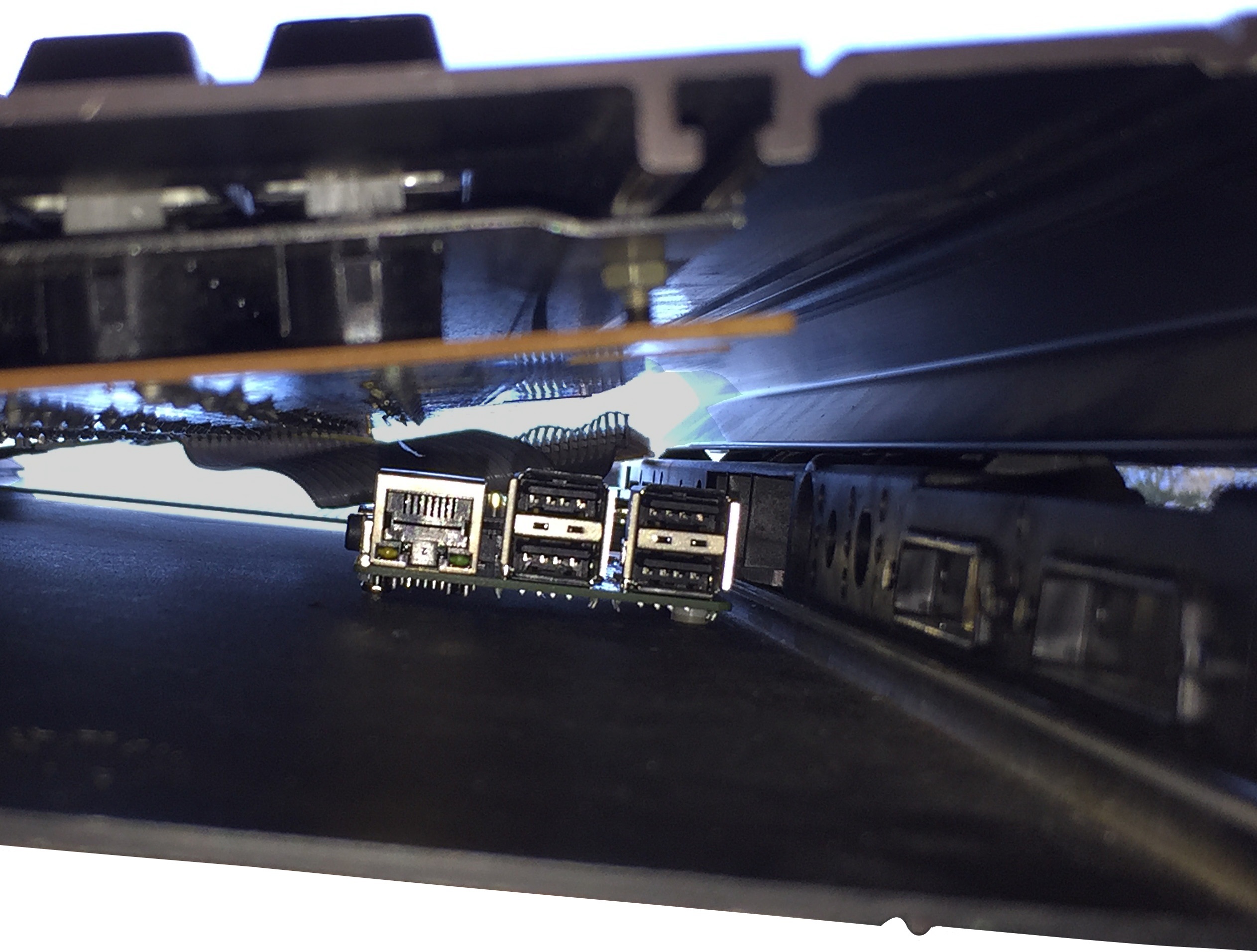
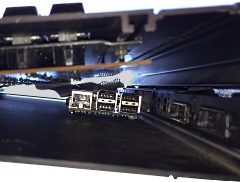
End on view, the photo is not too clear, but
hopefully, shows that there is more than adequate
clearance between the top of the Pi Network and USB
connectors and the underside of the MTX keyboard. |
 |
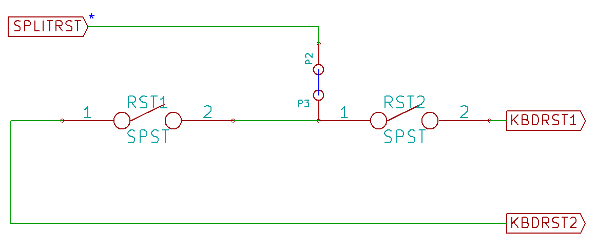
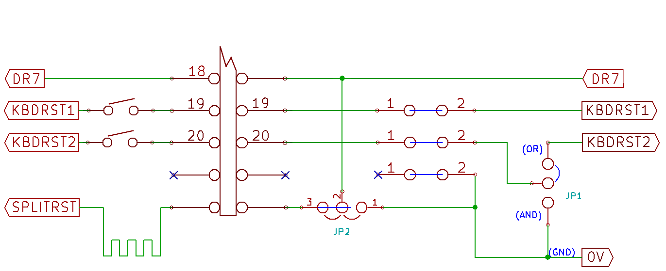
As noted above, the original
plan was to read the status of the MTX reset keys in
the same was as the other keys, using
drive and sense
lines. Since the reset keys are not used by the
native MTX software, this is not necessary and the
keys can be read directly by the Pi MEMU code to
initiate MEMU control functions.
For maximum
flexibility, jumpers are provided to configure the
reset keys as required. |
 |
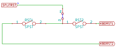
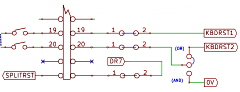
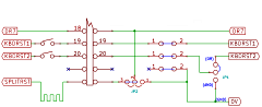
Circuit diagram showing the
reset jumper options
The two switches can be
either separate or commoned
JP1
directs the return from Key 2 to either a GPIO input
or ground
(JP2 should be open in this case)
JP2 sets the common point for Key 1 and Key 2 to
either DR7 or ground
(When using the two reset key switches for separate
functions) |
 |
Wherever possible, I wanted
to have the I/O connectors use the same positions as
the MTX connectors and have the port identification
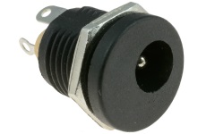
markings correct. The power connector was a little
awkward as the original MTX power plug is just
inserted through a hole in the plastic back panel
and plugged directly onto the PCB.
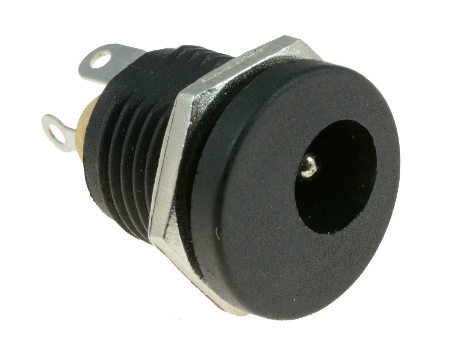
I used a
relatively large (12mm diameter) 5.5mm x 2.1mm DC
power socket like this one and made a couple of
supports put of a piece of strip-board to allow the
power plug to mount in the power input cut-out. |
 |
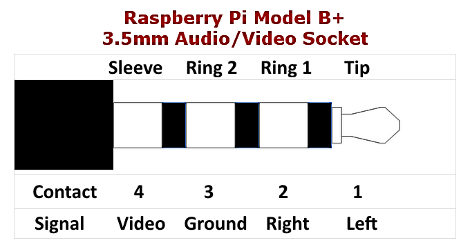
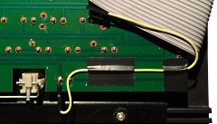
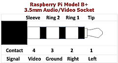
To save board space on the
Model B+, the PCB has a 3.5mm jack socket which is
used to connect the stereo audio and composite video
outputs that were on two separate connectors
in earlier models.
Although I could just
have used a suitable cable and terminated the ends
directly onto the connectors on the rear of the MTX,
I did it slightly differently. |
 |
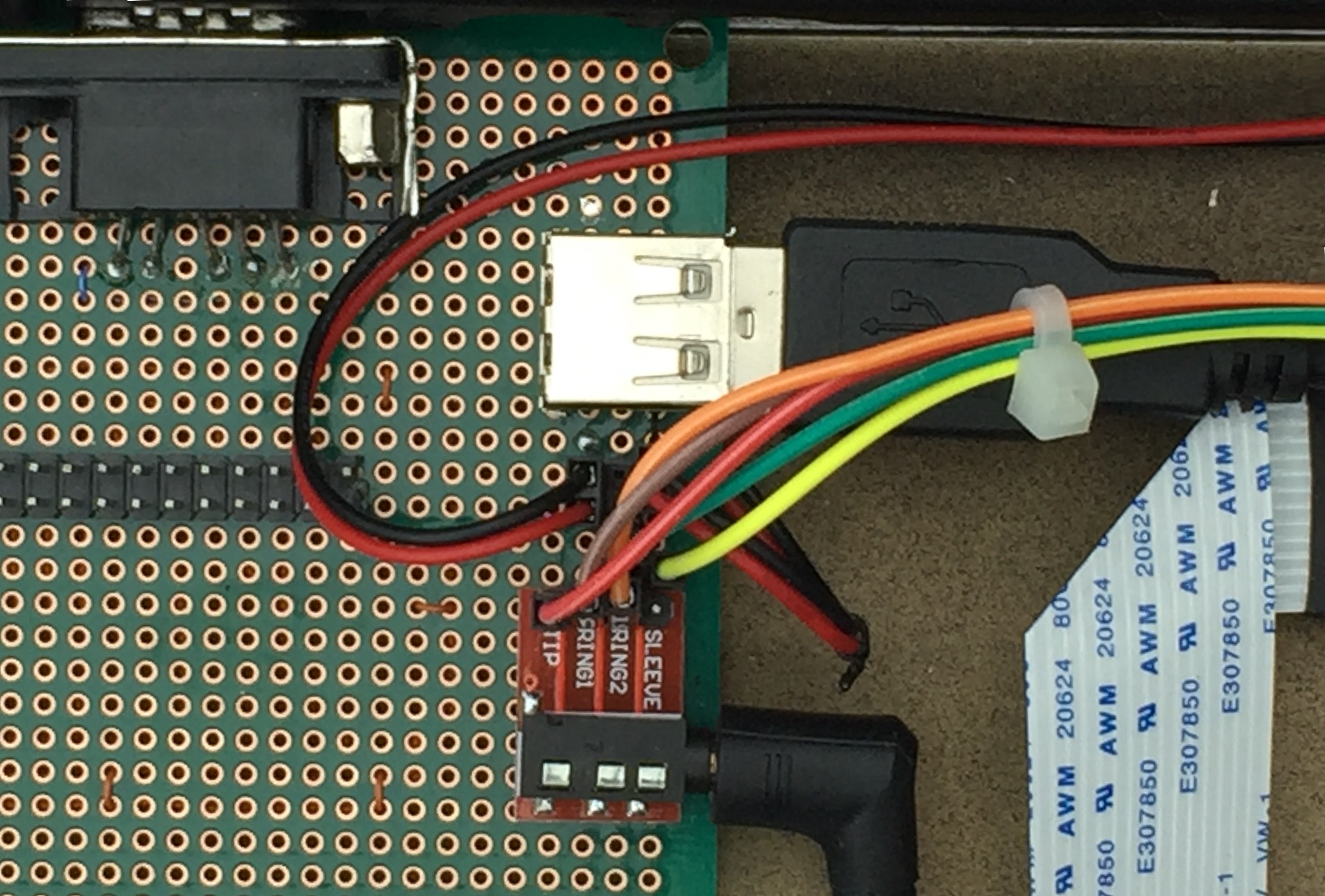
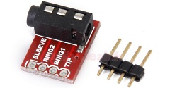
| I mounted a cheap (£1 off
ebay) breakout board on the keyboard PCB, cabled the
pin header to the AV sockets on the MTX rear panel and
connected the breakout board to the Pi with a
standard 3.5mm 4-pin cable. |
 |
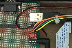
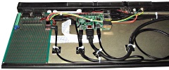
The patching for the power
and AV connectors.
The new 5.5mm barrel jack
socket on the rear panel is connected to a pin
header wired to a standard USB socket and a USB to
Micro USB cable takes power to the Pi.
The
audio and video signals from the PI 3.5mm connector
are split out for new 3.5mm stereo and phono video
connectors on the rear panel. |
 |
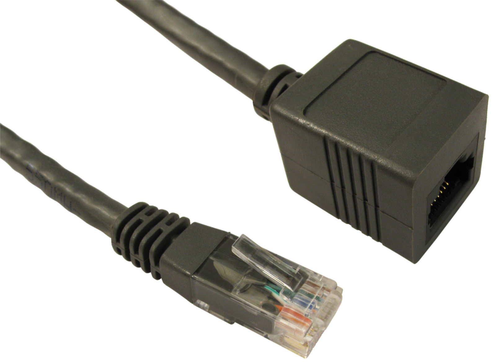
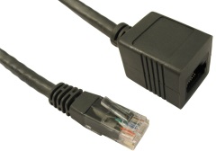
Installing software on the
Raspberry Pi is made much easier if the device is
connected to a network and the internet. In the
short term, I had planned to just have a short
length of network cable hanging out of the back of
the MTX case, but another trip to ebay revealed
short (0.5m) RJ45 extension cables like this one.
The flats on the female end make it suitable for
attaching to the base of the MTX case with a double
sided "sticky" pad. |
 |
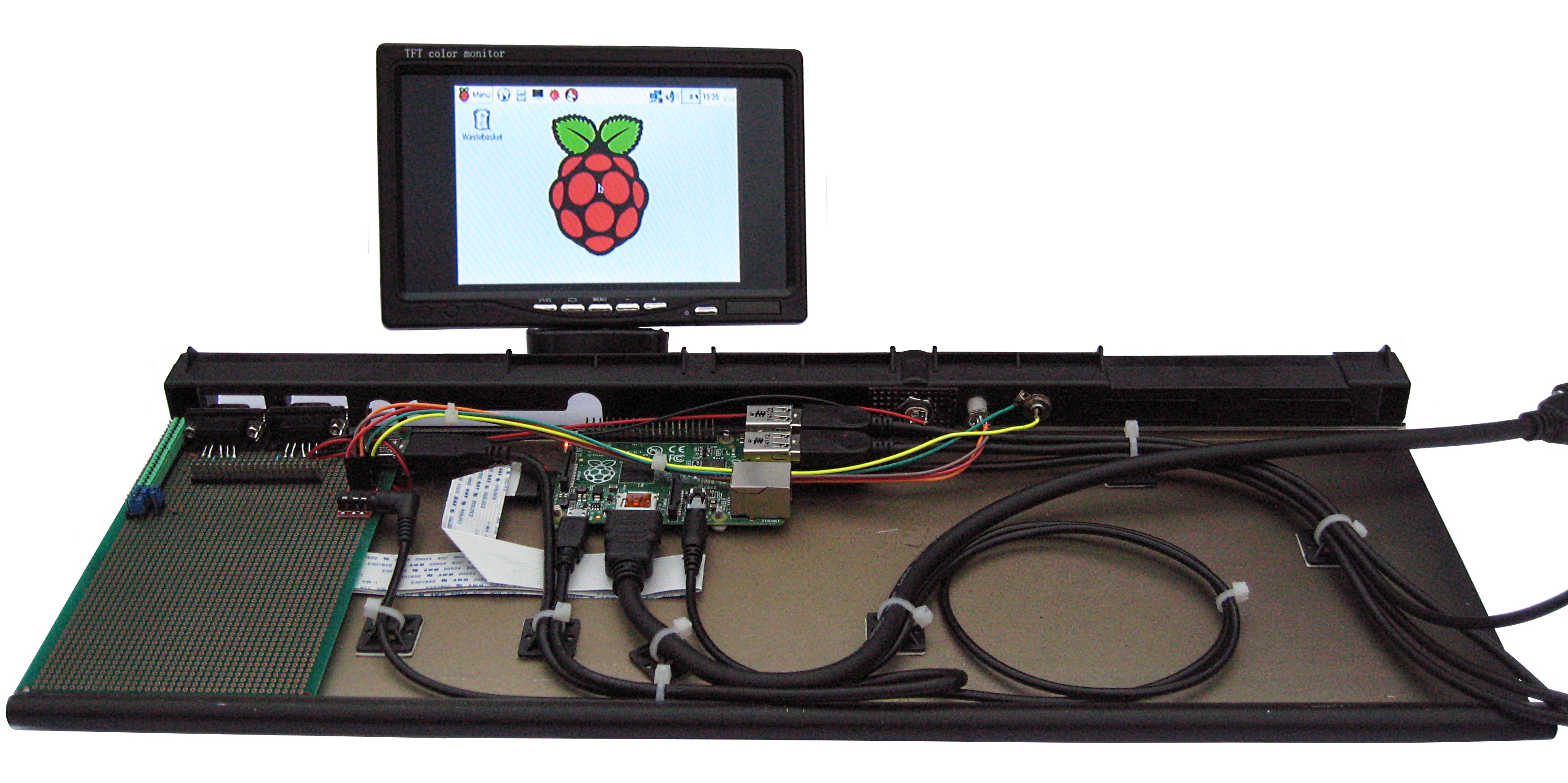
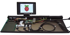
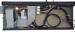
The Pi connected up and
booting to the
Raspbian
GUI, using my cheap 7" LCD monitor for initial
testing.
The keyboard interconnecting
ribbon cable has been removed for clarity and the
photo is also missing the network connection cable,
the easiest way of getting the MEMU software on the
Pi was to copy it over from a network share. |
 |
The HDMI and USB ports have
short patch cables fitted that exit the right side
of the case. The cables are
fitted with bulkhead connectors - I had intended to
mount the connectors on the end plate, but it would
be better to move the Pi to the extreme right and
have the USB and network ports flush with the end of
the case.
An SD card extender cable moves the
SD card slot to the left edge of the case |
 |
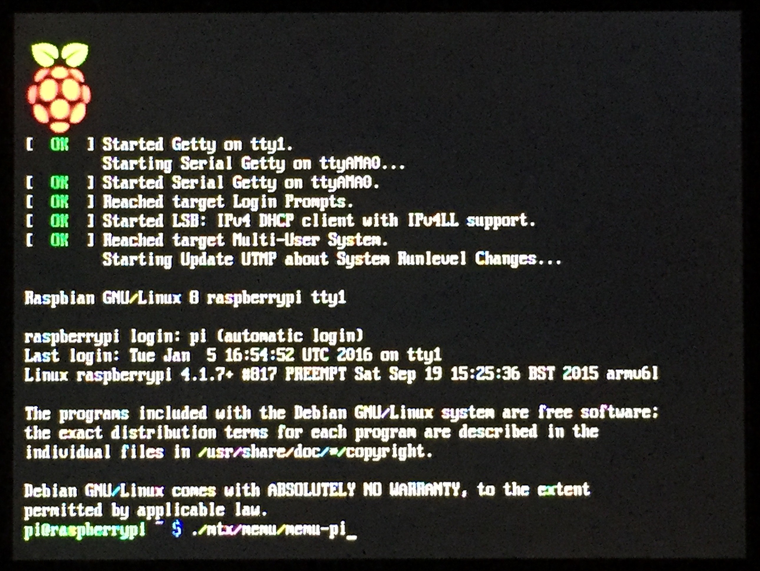
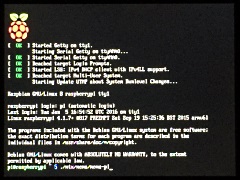
With the Raspbian Jessie
operating system loaded and Bill's
MTX-Pi version of his MEMU
installation extracted to the Pi
home directory, the system can be started from the
command line by entering :
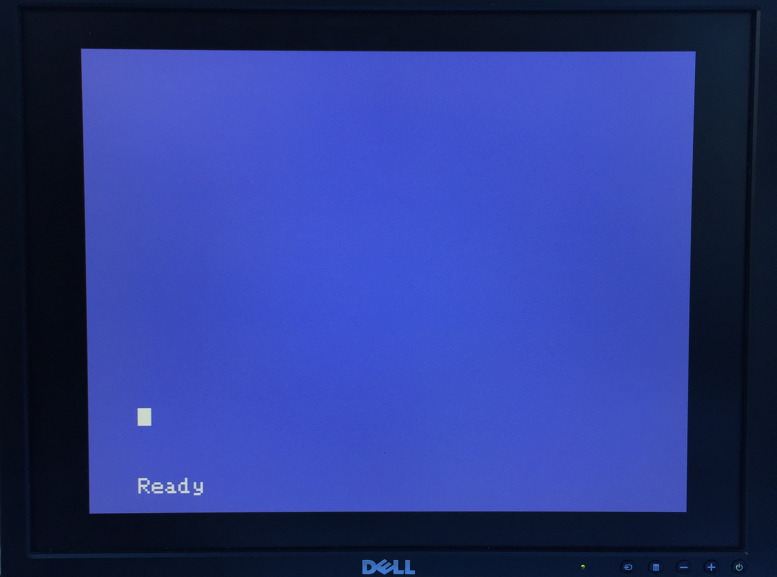
./mtx/memu/memu-pi
(In these screenshots, I am using the composite
video output to a Dell 2007FP monitor which results
in less than optimal video output) |
 |
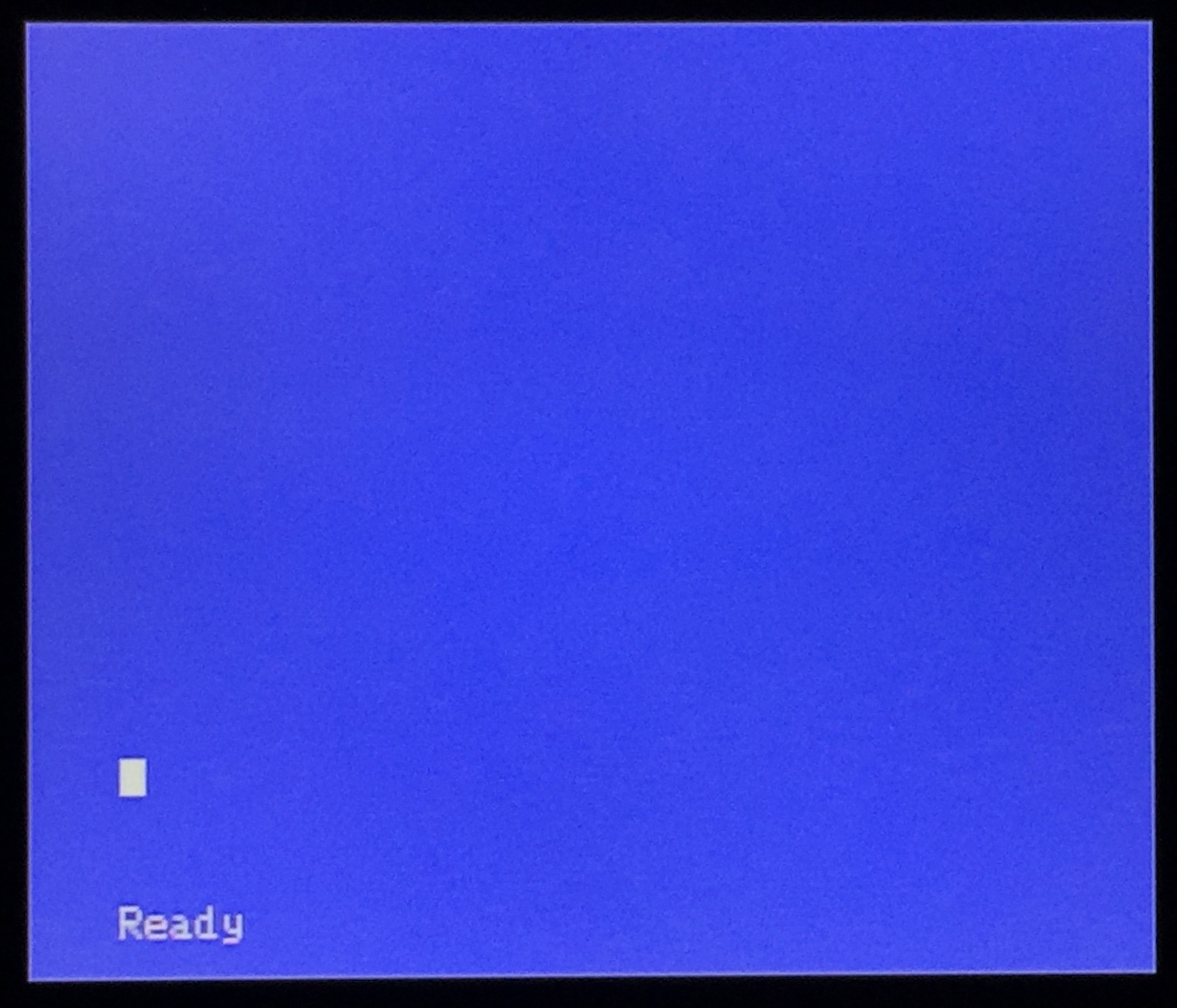
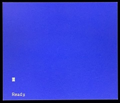
Success !
The familiar MTX "Ready"
prompt
(At this point, the MTX keyboard has
not been connected to the Pi,
only due to the fact that the interconnecting ribbon
cable is faulty.) |
 |
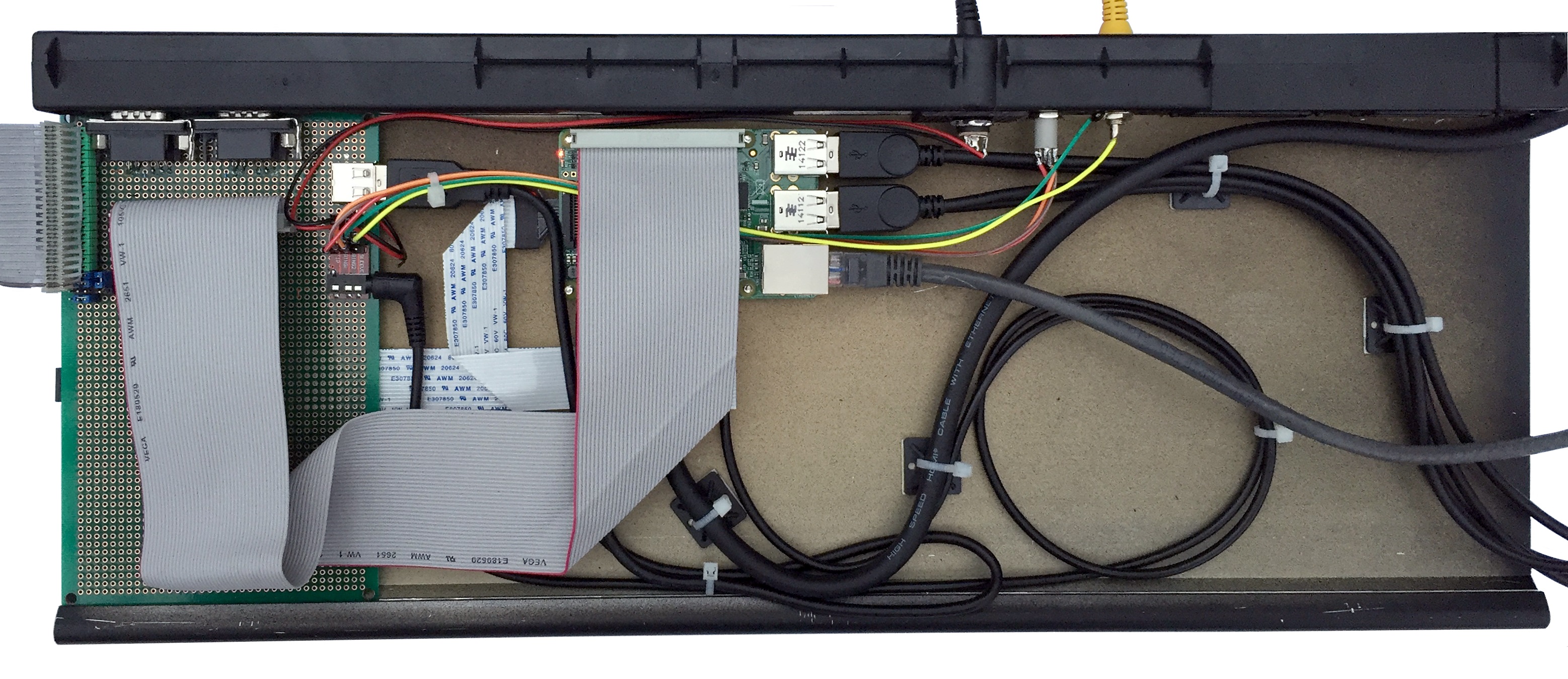
| Final fit, showing the
keyboard interconnect cable - a standard 40-pin IDE
cable |
 |
| |
|
| To be continued . . . . . |
|
| |
|
|
Preparing the Raspberry Pi |
| At the time of writing, the
latest version of the
Raspbian
operating system for the Raspberry Pi is based on
the "Jessie"
version of Debian
Linux. The Raspberry Pi website has an
overview of the differences between
Jessie and the previous
Wheezy releases, but the most
important difference for MTX-Pi is that
sudo
is no longer needed to access the GPIO functions. |
 |
| The
Raspberry Pi website recommends that a clean
install of Jessie is to be
preferred over an upgrade to Wheezy.
Download the Zip file (1.24GB) from the
Raspberry Pi downloads page to another PC - in
my case, running Windows. |
 |
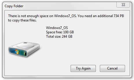
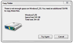
The Zip file contains an SD
card image which decompresses to 4GB, the built-in
unzipping tool in some versions of Windows,
including the 64-bit version of Windows 7
Professional that I am using, is not able to handle
archives of this size and generated the error shown.
The file can be successfully unzipped with the
free Windows version of the
7-Zip archive
utility. |
 |
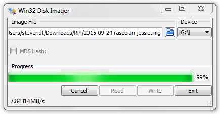
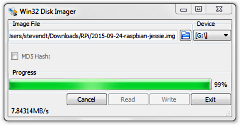
The image file should be
written to a [micro] SD card with a disk imaging
tool - it cannot just be copied to the media.
Win32 Disk Imager is available from
SourceForge on
its Project page
|
 |
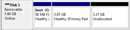
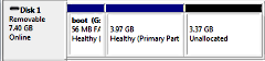
| When written to an 8MB SD
card, the image produces a 54MB Windows readable FAT
formatted partition, an approximately 4GB Linux
partition with the remaining space unallocated. |
 |
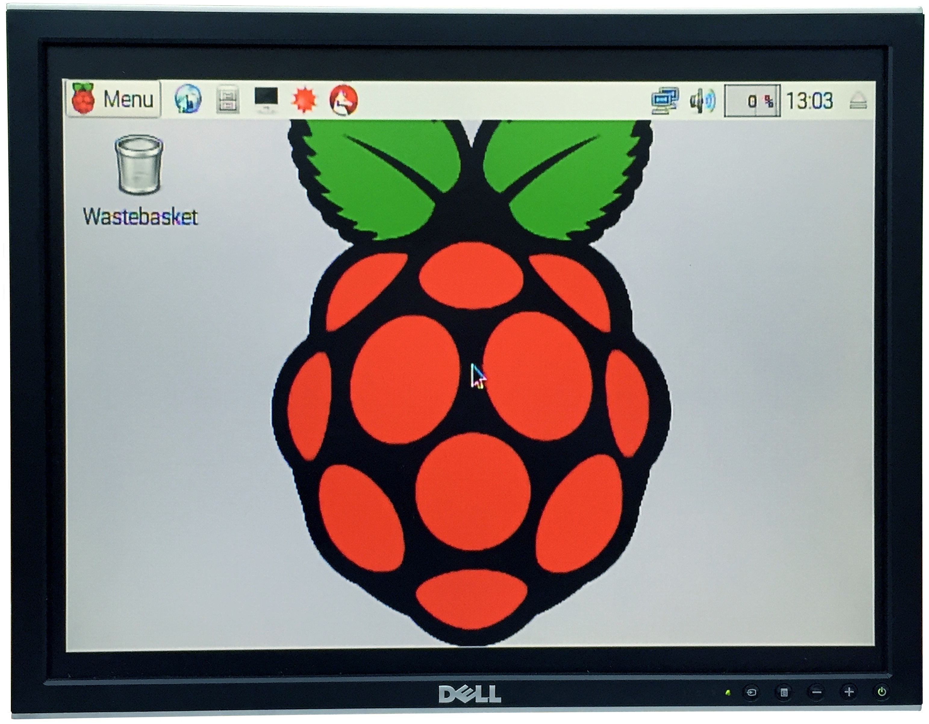
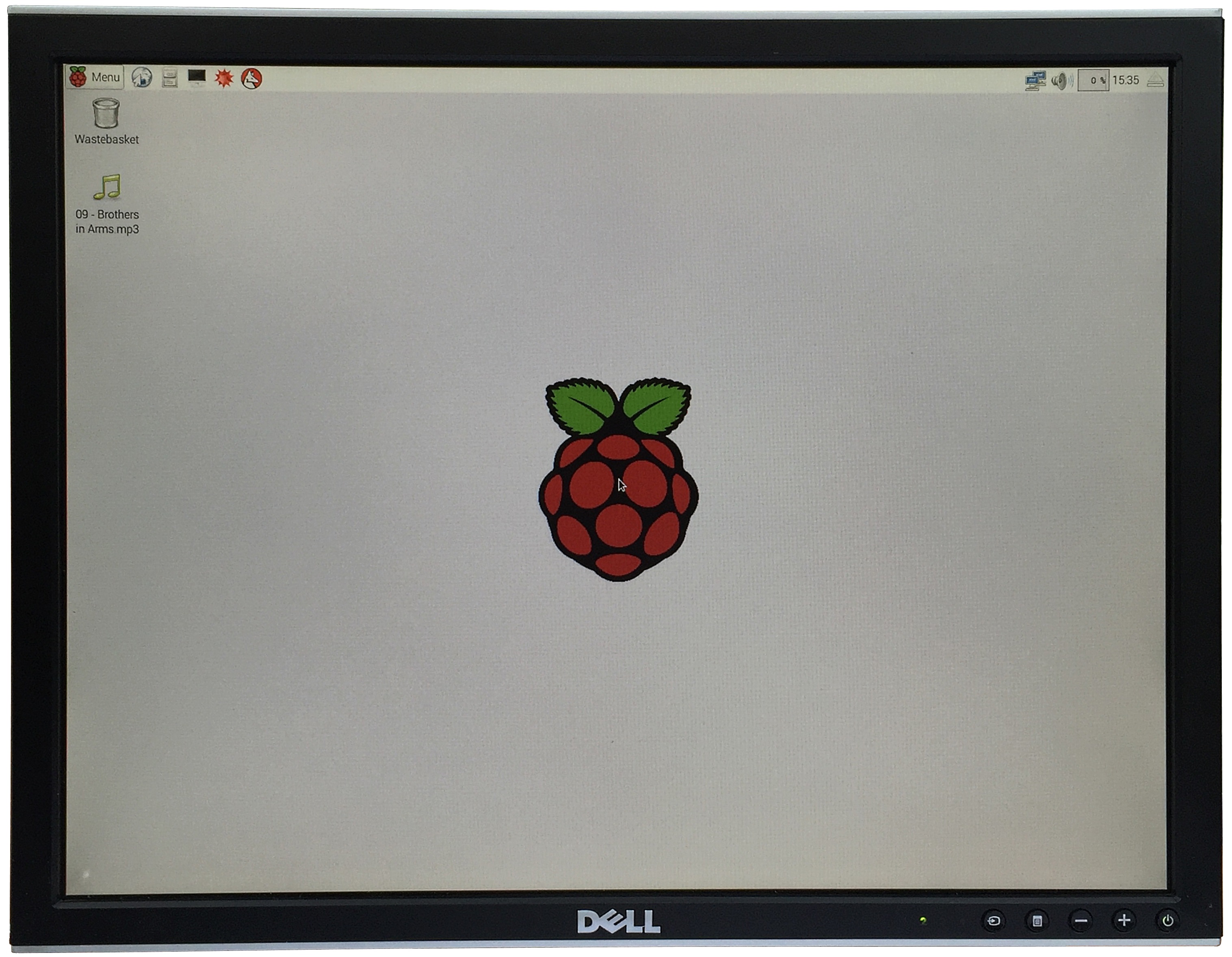
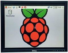
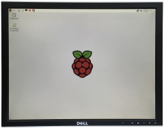
With the SD card inserted,
powering on the Pi should boot to the Raspbian
X-Windows desktop as shown.
For convenience,
at this point, I was using a Dell 2007FP monitor in
composite mode. Eventually, I will be using the Pi
HDMI output, but this was fine for setting up the
system, although the quality was not great. |
 |
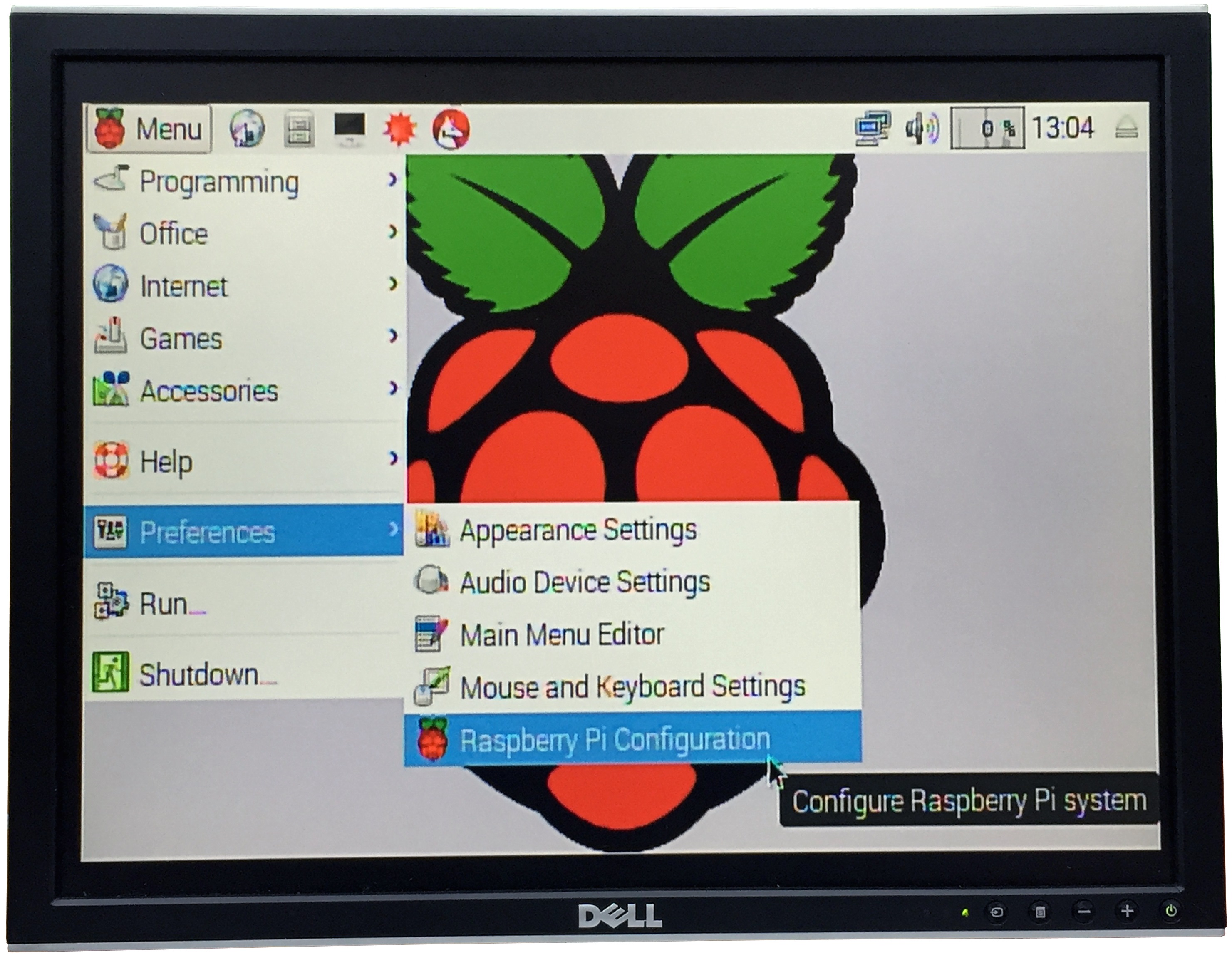
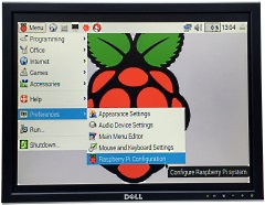
| Since this Pi is intended to
run MEMU full time, some changes to the system
configuration should be made from the
Raspberry Pi Configuration option,
available from the Menu
bar. |
 |
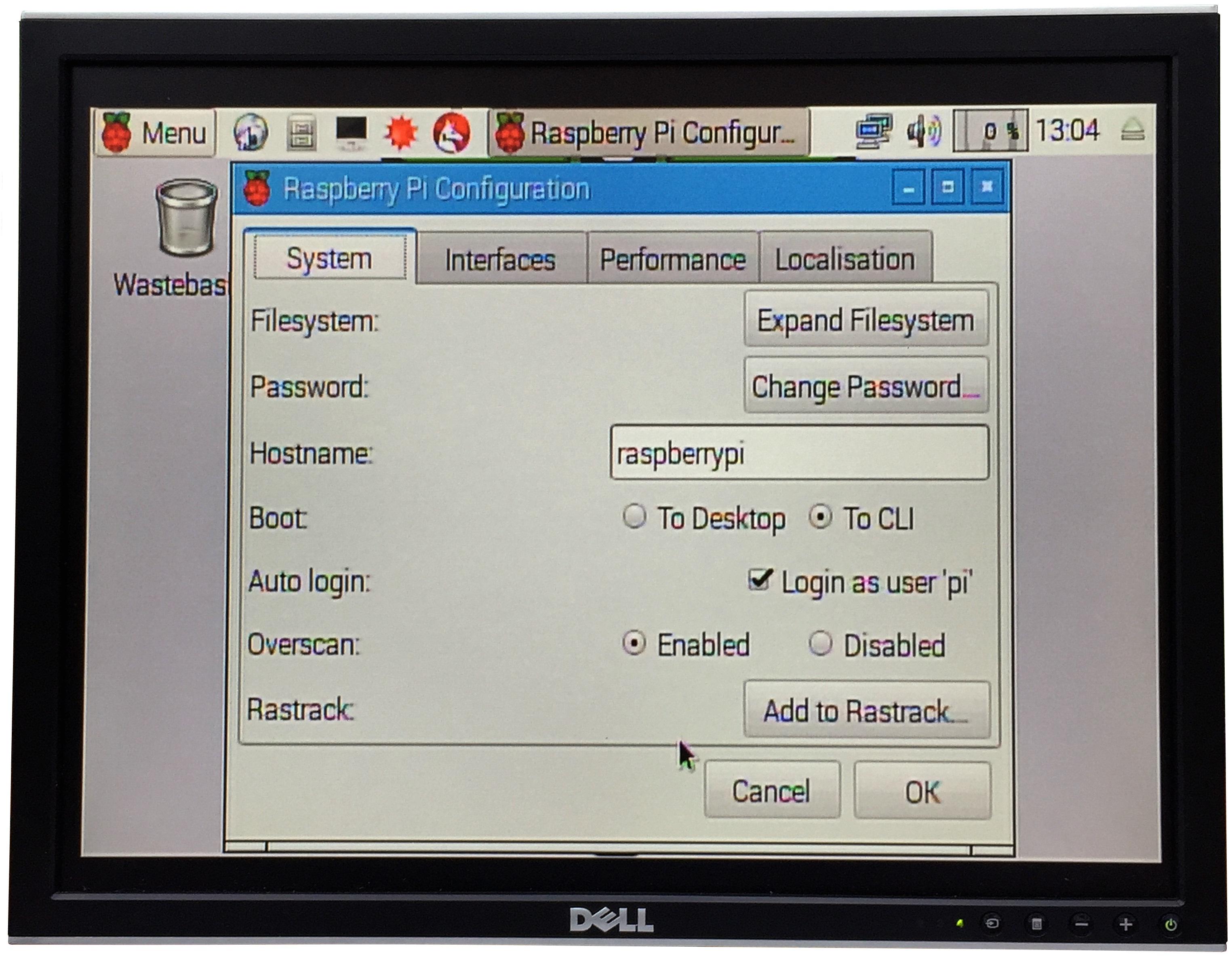
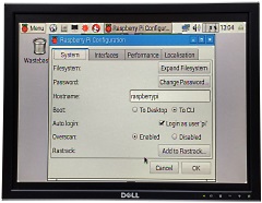
In normal circumstances, you
will not need to use the
GUI and want the system to startup and log on
automatically.
From the System
tab, set the Boot option
to
CLI (Command Line Interpreter) and enable
Auto Logon as the pi user.
(If you need to use the GUI at some point,
entering "startx" at the
command line will start the X-Windows interface) |
 |
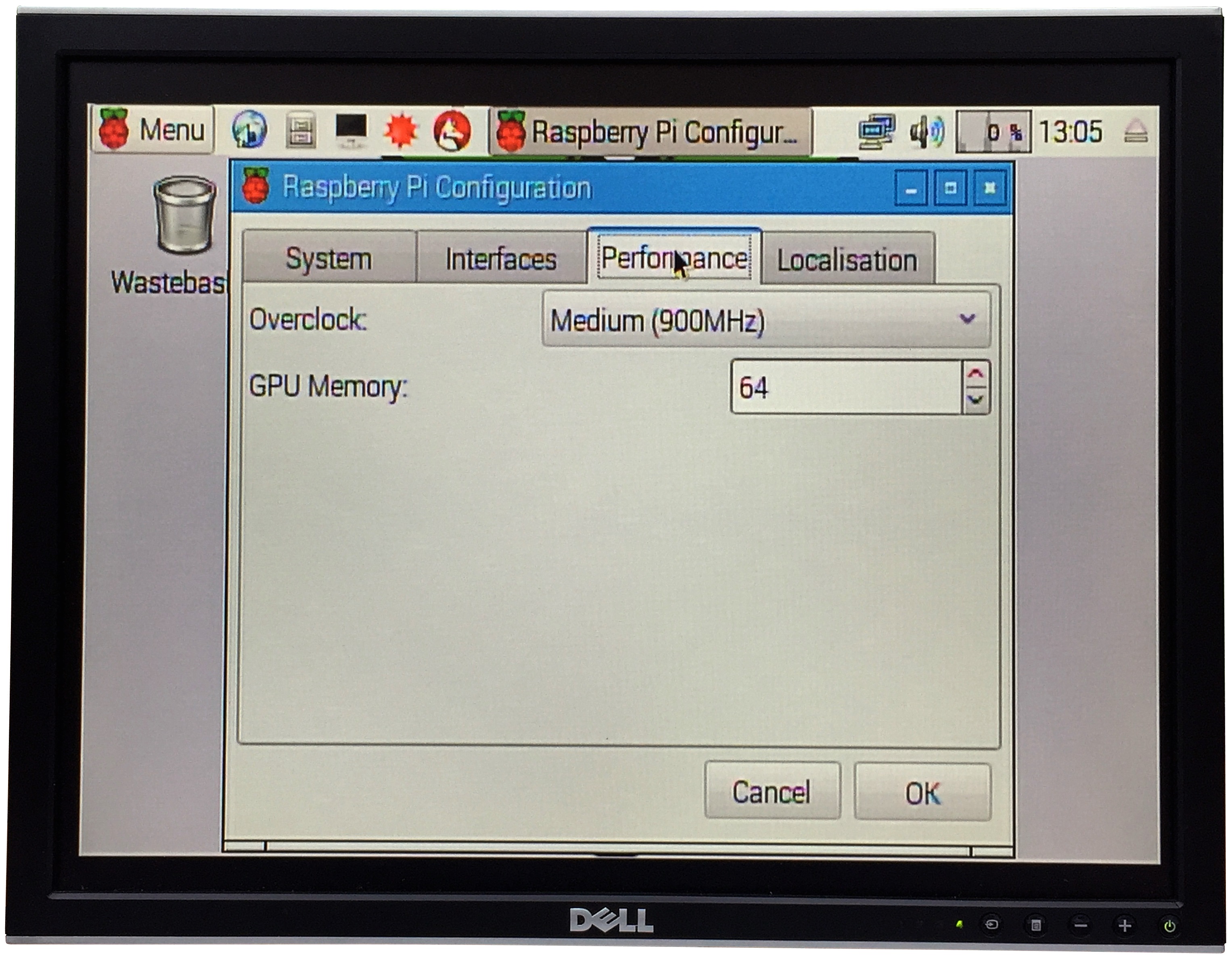
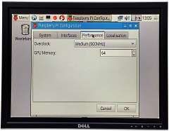
The default CPU speed for
the Pi is 700MHz, but it can be safely over-clocked
using the Overclock
parameter from the Performance
tab.
Although it is not really necessary to
run MEMU, I opted to use the Medium
setting and run the CPU at 900Mhz. The system will
almost certainly run faster, but as I wanted a
stable system, rather than necessarily the fastest,
900MHz will be more than adequate. |
 |
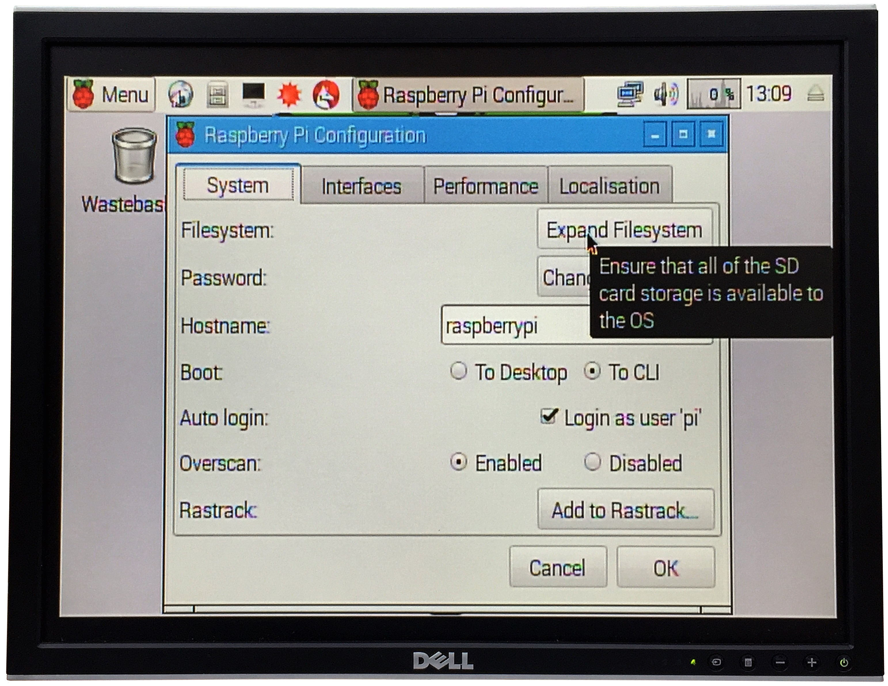
Although it's highly
unlikely that you would use anywhere close to the
free space on the default 4GB partition (~580MB
free) for MEMU, the Expand Filesystem
option under System
preferences is used to make the rest of the free
space on the SD card available to the Pi. (A reboot
is required for the change to take effect.)
In my case, using an 8GB SD card, the free space
increased from 580MB to 3.8GB. |
 |
When Bill was
looking to add GPU acceleration to MEMU he passed on
some information on how video scaling worked for
MEMU on the Raspberry PI.
"The resolution is
(in effect) the same as the original MTX resolution.
This is then scaled up to fit the available screen
pixels, each MTX pixel becoming a number of pixels
on the RPi display. Exactly what the scaling is will
depend upon the pixel size of the display and on the
MTX screen size (256 x 192 pixels). The up-scaling
is always an integer number of pixels in each
direction."
Bill added an additional
configuration option to the memu-pi.cfg
file : -gpu-mode.
This
option defines whether the up-scaling is done in the
ARM processor or in the GPU.
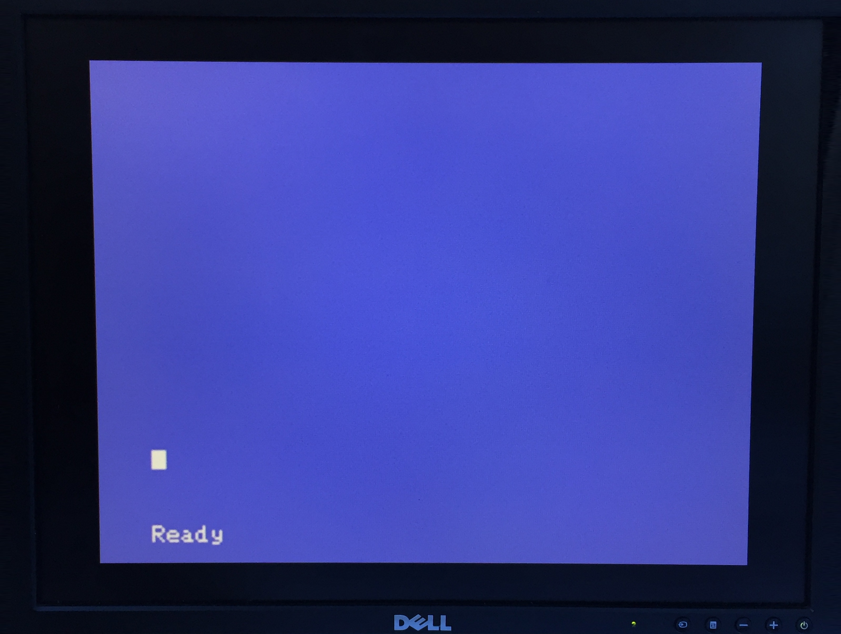
The screen shots
below are taken with my iPhone camera, the images
suggest that the colour of the text has a bluish
tinge, but in all cases, it is a pretty good
"white". The images are intended to show the effect
of the -gpu-mode setting on the
"crispness" of the text display. |
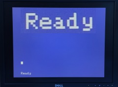
| -gpu-mode 1
Up-scaling is performed by the
ARM processor
|
 |
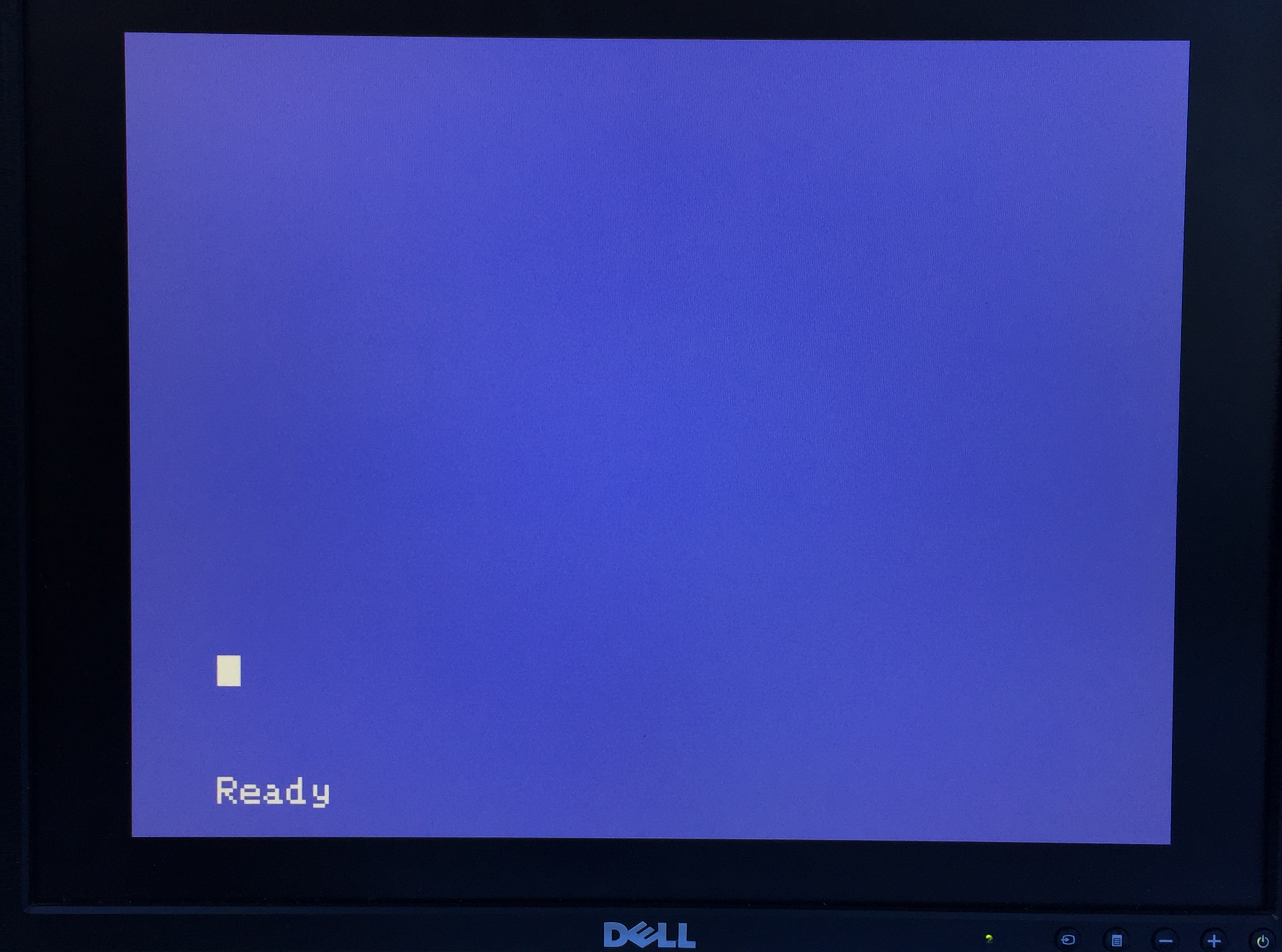
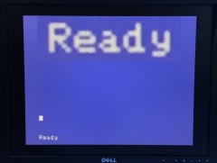
-gpu-mode 2
The GPU performs up-scaling with
interpolation.
As Bill says, this mode
"emulates a fuzzy 1980's TV" - you can use this mode
for the real 1980's retro experience ! |
 |
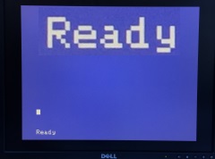
-gpu-mode 3
The GPU performs up-scaling, but with no
interpolation (temporarily changes the scaling
kernel).
Modes 2 & 3 are making more use of
the GPU and less of the ARM, so they should be
better than mode 1, particularly on high-res HDMI
screens. Based on my limited testing, Mode 3 seems
to be the best one for me with my Dell FP2007
monitor using an HDMI-to-DVI-D cable.
|
 |
Now with an HDMI to DVI-D
cable connected between the PI and my Dell FP2007, I
can use HDMI mode and take advantage of the much
bigger X-Windows desktop.
The DVI-D
connector does not support audio, so I am still
using the PI's 3.5mm audio output, connected to the
Dell Soundbar audio input. |
 |
| |
|
|
Preparing MEMU |
A "normal"
installation of MEMU on a Raspberry Pi is described
on my
MEMU-Pi pages, there you can find a description
of how to compile and install MEMU from its source
files.
For MTX-Pi, Bill kindly created a
pre-built installation for me, all that required was
to copy the
.tar file into the Pi home directory and
decompress the archive. |
| |
|
| To be continued . . . . . |
|
| |
|
|