|
 |
The Memotech MTX Series |
 |
MEMOTECH DISK OPTIONS
SDX Disk Upgrade
(SDX
Photos)
SDX Disk Upgrades
As described on the FDX disk option
page, Memotech released a single 5.25" drive upgrade in an FDX
case, which is sometimes referred to as an SDX system, however,
the 5.25" upgrade was not labeled as an SDX. The Memotech
Single Disc Operator's Manual appears to be a compilation of
various other documents and does not present a very clear
picture of the SDX options, but does describe both the Single
Disc FDX type and the two SDX badged products that were released
:-
External Drive SDX
This upgrade allowed the user to install one or two floppy
disk drives alongside the MTX, but with a much reduced footprint
from the FDX option. The disk controller was in an aluminium
case, profiled to match the MTX, which connected to the
expansion connector on the left hand side of the MTX. The
product datasheet for the original SDX disk option notes that
the disk controller is an FDC03, although some
external disk SDX systems used an FDC05 controller (no FDC04
controller boards have been seen and probably do not exist).
The only obvious difference between the two controller
types is that the FDC03 controller does not use an external
power supply, it gets 5VDC from the MTX edge connector. The
FDC05 has a 3.5mm jack socket on the rear panel which is used to
supply additional 5VDC power. The floppy disk PSU provided an
additional 5V supply to the disk controller via a small power
cable between the disk drive unit and the SDX controller,
terminated with a 3.5mm jack plug at both ends. I assume that
Memotech found that the current draw over the MTX edge connector
was too great and added external power to later controllers.
The disk controller was capable of controlling two floppy
drives which could be a mixture of 5.25" and 3.5", although
Memotech only supplied 5.25" disks in this configuration. The
floppy drive was housed in its own case which included the
drive's power supply;
a ribbon cable connected the floppy drive to the disk
controller.
The external SDX was available with Type 03 (320kB) or Type
07 (640kB) disk drives but were too expensive for the majority
of MTX owners to consider. Late in the machine's life, Memotech
made lower capacity drives available with Type 00 (80kB) and
Type 02 (160kB) disks but they were introduced too late to make
much of an impact on sales.
Supported Disk Formats
The
SDX FDC03/05 disc controller supported a subset of the config codes
contained in the
PROM of the FDXC1 controller :-

These config codes allowed the use of 100kb, 250kb, 500kb and
1MB (unformatted sizes) floppy disks, the FORMAT program was
capable of formatting up to 8 different configurations, i.e.,
the four sizes on either 5.25" or 3.5" disks.
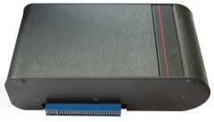
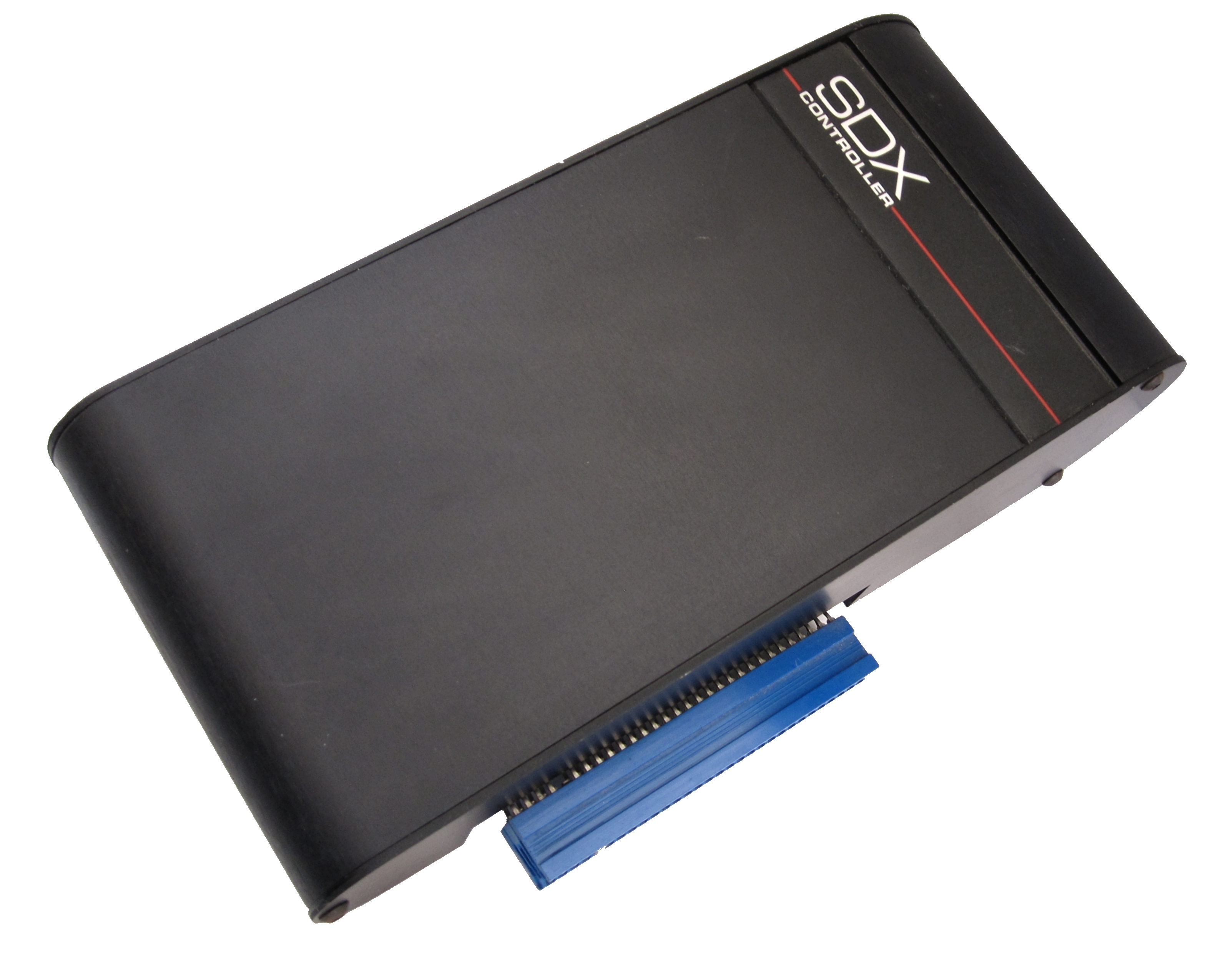
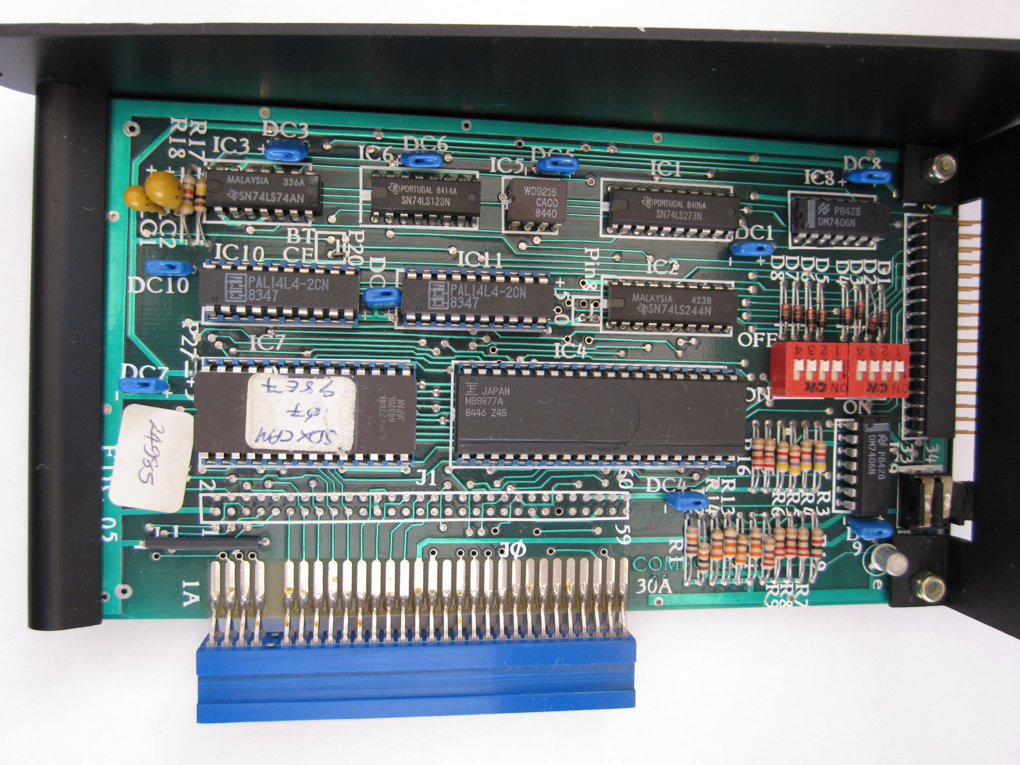
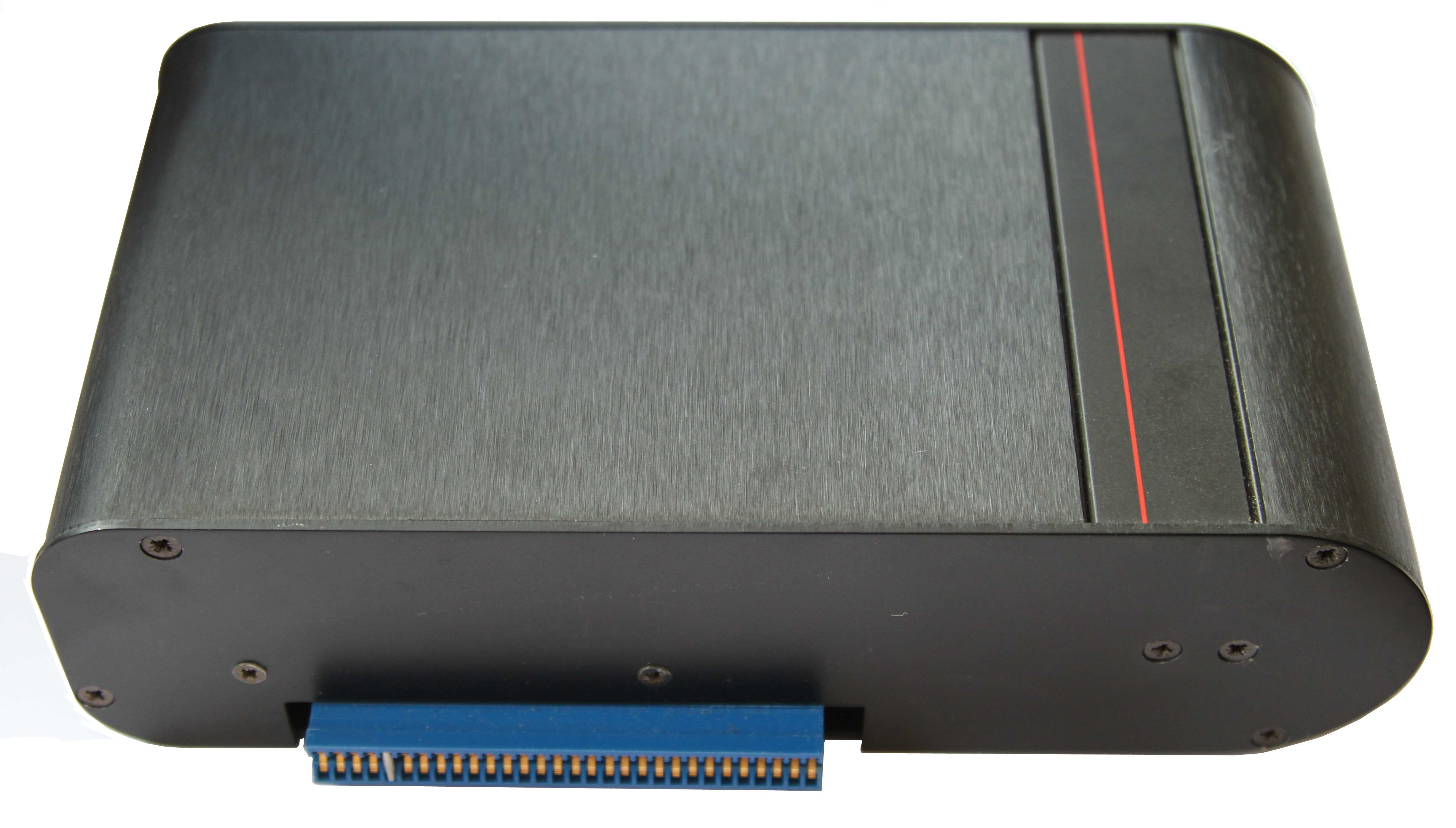
The first
style of "new" SDX controller.
The case had a
wedge profile that matched the MTX.
Additional
photos can be found on the SDX
Photos page |
 |
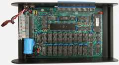
The PCB has
2 packs of 4 dip switches that were configured for the
attached drive(s). The set at the rear of the case
configure the first drive. The ROM often, but not
always, carries a two digit number that signifies the
drive type - in this case, "Type 02" (SS/SD), Type 03
(DS/SD) are more common.
| SW1 (ON) |
Head Load solenoid present on drive |
| SW2 (ON) |
Double Sided Drive |
| SW3 (ON) |
96 TPI Drive (80 Tracks) |
| SW4 (ON) |
Drive Step Rate 6ms (OFF = 12ms) |
|
 |
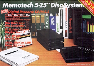
There is a copy of the Memotech "Flyer" for the "Memotech
5.25" Disc System" on the Articles
page which includes some technical data on this version of the
SDX,
Internal Drive SDX
For the MTX512S2, Memotech combined the SDX disk controller
and a 3.5" floppy drive into a single unit which connected to
the expansion connector on the left hand side of the MTX. Due to
the extra height of the floppy drive, the profile no longer
matched the contours of the MTX, but it was a much neater
solution. The combined 80 Column and RS232 board was also
installed in the MTX512S2.
The disk controller was combined with a Silicon Disk board,
which allowed a Silicon/RAM disk up to 512kb to be configured.
As the disk drive did not have its own power supply like the
external floppy disks, this controller module also required
external power to be provided to supply the required voltages
for logic circuits and disk drive operation. In this case, the
SDX unit has a 6-pin DIN power connector like the MTX power
input and needed a second MTX power supply unit.
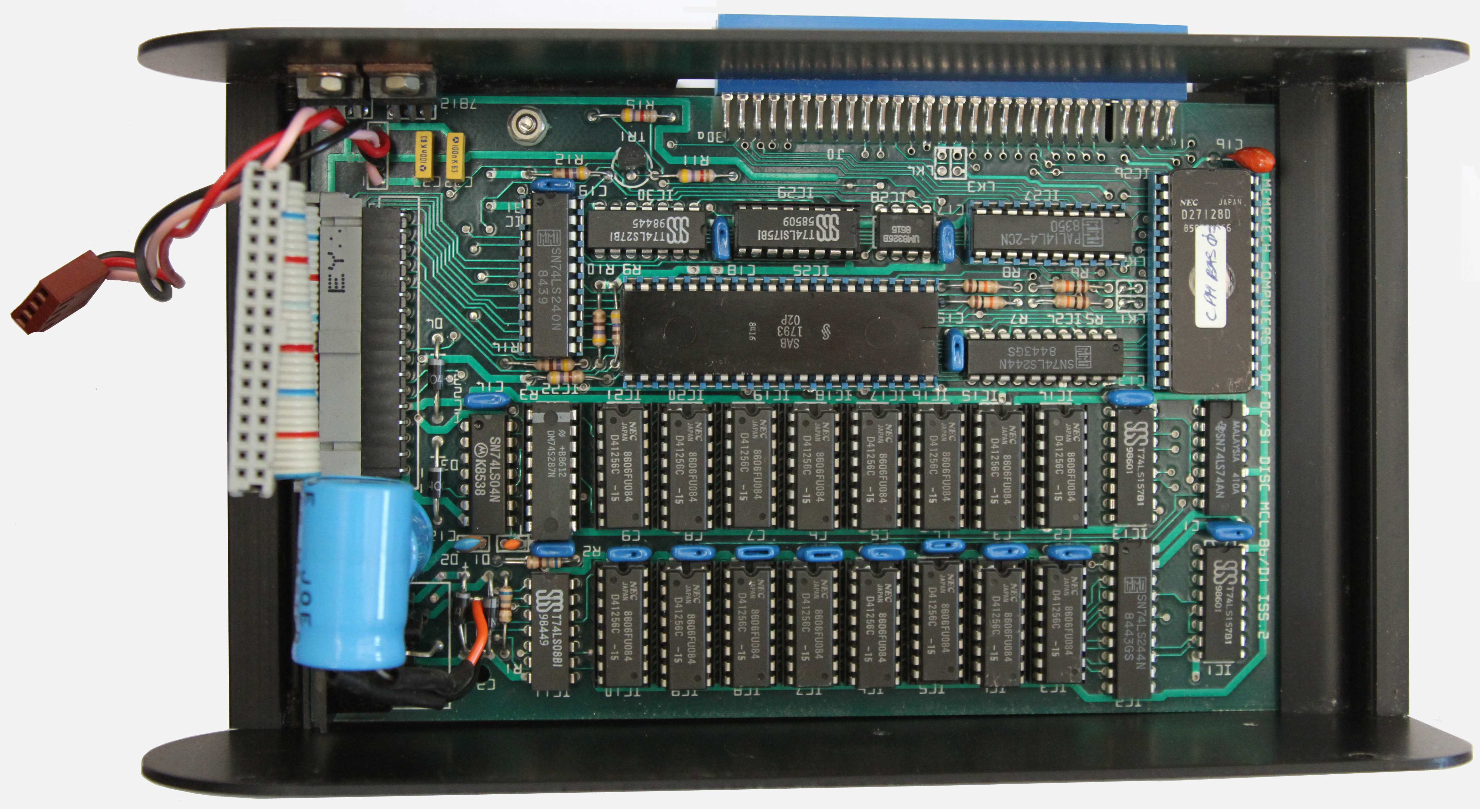
The later
version of the SDX released for the MTC512S2,
This case forgoes the wedge profile and has a squarer
form that allows the 3.5" disk drive to be mounted
inside the case.
Again, additional photos can be
found on the SDX Photos page |
 |
The
controller used here does not have any drive
configuration switches, the ROM is hard coded to expect
a DS/DD 80 track drive.
The controller could
optionally be fitted with 512k of RAM as shown here
which was typically used as a RAM disk. |
 |
Expansion Options
Memotech developed a combined 80 Column and RS232 board which
could be attached to the internal edge connector of the MTX,
this allowed the SDX system to be upgraded to CP/M with a
similar package of software as the FDX, including NewWord and
SuperCalc.
Supported Disk Formats
I believe that the disc controllers in the later
version of the SDX was programmed with config codes "00" to "07"
as per the FDX FDCX1, however, the SDX was hard coded to just
allow types "03" and "07", i.e., DS/DD 40 Track and DS/DD 80
Track respectively.
All 3.5" disks are 80 Track, and apart from the
very earliest, are double-sided and either double (DD) or high
(HD) density. Higher capacity 3.5", HD disks, with a
formatted capacity of 1.44mb were introduced in the late 1980s
and became a standard (defined in ISO9520) in 1989. These disks have an
additional hole in the case, opposite the write protect switch,
to allow the drive to determine the disk density. You can force
a HD disk to be treated as a DD disk in an HD drive by covering the media
density hole with opaque tape (though this is not really a good
idea as explained on
this page).
A comparison of a number of PC formats and the
SDX format is shown in the table below :-
| Target hardware |
|
SDX 02 |
SDX 03 |
SDX 07 |
IBM PC |
IBM PC |
IBM PC |
| Disk Size |
inch |
5.25 |
3.5" or
5.25" |
5.25 |
5.25 |
3.5 |
| Bytes per Sector |
bps |
256 |
256 |
256 |
512 |
512 |
512 |
| Sectors per Track |
spt |
16 |
16 |
16 |
8 |
9 |
9 |
| Tracks per Side |
tps |
40 |
40 |
80 |
40 |
40 |
80 |
| Sides |
s |
1 |
2 |
2 |
2 |
2 |
2 |
|
Formatted
capacity =
bps
* spt * tps * s / 1024 |
kb |
160 |
320 |
640 |
320 |
360 |
720 |
A 3.5" drive, with appropriate disk formatting,
should be compatible with Type 03 (40 Track) or Type 07 (80
Track) config modes, but neither of these SDX modes are
supported by the standard DOS or Windows formatting utilities.
However, disks can be formatted for SDX use on a PC using low
level disk tools such as Teledisk 2.15, available on the
Tools page. Version 2.15 is preferred
over 2.16 as it supports Direct I/O whereas 2.16 does not.
However, this is NOT enough to allow the disks to be used by SDX
- see the next section for the reason why.
SDX System Disks for Non-CP/M
Systems
NB: ALL disks used with an SDX
BASIC (non-CP/M) system need to contain a copy of the SDX disk
system tracks, i.e., they MUST be
system disks. When an SDX system is powered on or reset, the
user should first enter a "ROM x"
command from BASIC, where "x" is the ROM ID of the disk
system ROM, which is usually "3", but may also be "5". Entering
this command causes the SDX to read the CP/M system from the
system tracks (0 and 1) and patch the data in RAM for use with
SDX disk USER commands (FORMAT, SYSCOPY, LOAD, SAVE).
If the disk in the drive cannot be read or does
not contain the system tracks, the MTX will report the pretty
unhelpful "DISC ERROR" message. This
message can also indicate that the disk format (Type 03 or Type
07) does not correspond to the configuration set on the disk
controller's hardware bit switches.
This point is key to being able to use your SDX,
so it's worth restating,
you cannot use a non-system disk to start an SDX !
It follows then, that if you obtain an SDX controller and disk
drive, you can not get it working
without access to a pre-formatted and system enabled SDX disk.
With access to such a disk, you can then, and only then, create
additional disks as required with USER FORMAT and USER SYSCOPY.
Without this knowledge, it is very easy to
conclude that the controller or disk drive is faulty or the disk
cannot be read, whereas you may just have an incompatible floppy
in the drive.
SDX System Hardware
Configuration
As described above, the SDX controller must be
compatible with the disk drive used. For the later version, only
a DS/DD 80 track drive can be used. For the earlier version, the
appropriate bit switch pack must be configured for the drive
type being used.
VVVVVVV delete VVVVVV
Disk Interface
As with the FDX system, the pin numbers for connector J2 on the
FDC03/05 board are derived from their correspondence with the
conductors in the ribbon cable - conductor 1 is marked with a
red stripe and makes contact with pin 1 on the connector.
Quoting from the FDX manual "Unfortunately, this scheme is not
used by disc drive manufacturers who number pins from the
opposite end." (Perhaps they should have said "we numbered the
pins the opposite way around from everyone else in the
industry?)
The FDX manual goes on to say, ""Don't worry about plugging the
connectors in the wrong way round - no electrical harm will be
done, but any discs installed may have their data and format
corrupted." The connector has alternate (even numbered) pins
grounded, the table below gives designations for the remaining
pins.
What this means in practice is that the ribbon cable needs to be
connected with a twist such that Pin 1 at one end connects to
Pin 1 of the interface and Pin 1 at the other connects to Pin 34
on the disk drive (or vice-versa).
|
Connector Pin-Out |
| Pin |
|
| 1 |
(not
used) |
| 3 |
SIDE SEL |
| 5 |
READ DATA |
| 7 |
WRITE
PROTECT |
| 9 |
TRACK 00 |
| 11 |
WRITE
GATE (write enabled) |
| 13 |
WRITE
DATA |
| 15 |
STEP |
| 17 |
DIRECTION
(head step direction) |
| 19 |
MOTOR ON |
| 21 |
DRIVE
SELECT 2 |
| 23 |
DRIVE
SELECT 1 |
| 25 |
DRIVE
SELECT 0 |
| 27 |
INDEX |
| 29 |
DRIVE
SELECT 3 |
| 31 |
(not
used) |
| 33 |
HEAD LOAD |
| Pin 33 and all
even numbered pins are tied together at 0V |
This information suggests that the SWx-1 DIP switch setting
(Head Load solenoid present on drive) is superfluous, with this
line grounded, even if the drive does have a head load solenoid,
the heads should be loaded as soon as the drive is powered on.
The SWx-4 DIP switch setting may be of limited use too. As might
be expected, older drives, particularly 5.25" ones have the
slowest step rates, with newer, especially 3.5", drives having
faster step rates. However, I not seen a noticeable difference
when this setting is changed, ever on 5.25" drives. It may be
that, provided that the drive can move the heads faster, the
read speed does improve for larger files that span multiple
tracks, but the difference is probably negligible.
The table below provides a
cross reference between the SDX pin-out and the standard used by
just about everyone else
| Pin |
Name |
Dir1 |
Description
(Original Shugart Interface) |
FDX J3
Pin |
Modern PC
Interface5 |
| Pin |
Description |
| --- |
|
|
Head Load (non-Shugart) |
333 |
--- |
|
| 2 |
/REDWC |
 |
Reduced Write Compensation (8"
only) |
--- |
2 |
Density Select |
| 4 |
/INU |
|
In Use (non-Shugart) |
--- |
4 |
(Not used) |
| 6 |
DS3 |
|
Device Select 32 |
29 |
6 |
(Not used) |
| 8 |
/IDX |
 |
Index |
27 |
8 |
(As Shugart) |
| 10 |
/DS0 |
|
Device Select 02 |
25 |
10 |
Motor Enable A |
| 12 |
/DS1 |
|
Drive Select 12 |
23 |
12 |
Drive Select B |
| 14 |
/DS2 |
|
Device Select 22 |
21 |
14 |
Drive Select A |
| 16 |
/MTRON |
|
Motor On |
19 |
16 |
Motor Enable B |
| 18 |
/DIR |
|
Head Step Direction |
17 |
18 |
(As Shugart) |
| 20 |
/STEP |
|
Step |
15 |
20 |
(As Shugart) |
| 22 |
/WDATA |
|
Write Data |
13 |
22 |
(As Shugart) |
| 24 |
/WGATE |
|
Floppy Write Enabled |
11 |
24 |
(As Shugart) |
| 26 |
/TRK00 |
|
Track 0 |
9 |
26 |
(As Shugart) |
| 28 |
/WPT |
|
Write Protect |
7 |
28 |
(As Shugart) |
| 30 |
/RDATA |
|
Read Data |
5 |
30 |
(As Shugart) |
| 32 |
/SIDE1 |
|
Head Select |
3 |
32 |
(As Shugart) |
| 34 |
/RDY |
|
Ready (non-Shugart) |
--- |
34 |
(As Shugart)5 |
|
Odd numbered pins are
connected to ground |
|
|
|
|
Notes : |
|
1 Direction
indicates that the signal direction is from the
controller to the drive |
|
2 Legacy drives from different
manufacturers may have ID select numbered 0 to 3 or
1 to 4 |
|
3 Pin 33 on the SDX FDC board is
connected to ground, leaving this signal always
ON, see the SDX schematic |
|
4 A PC Floppy Disk interface
only supports the use of two drives |
|
5 I don't think this is
actually used on a PC |
Drive ID Selection
The original design of the floppy disk drive used
jumpers on the drive to set its address which would be
selected by controller pins 6, 10, 12 & 14. Most modern drives,
particularly 3.5" drives for PCs, do not have ID jumpers and are
factory configured to have an ID of 1. (It makes for quicker
assembly when the drives do not need to be individually set up
by the PC manufacturer.)
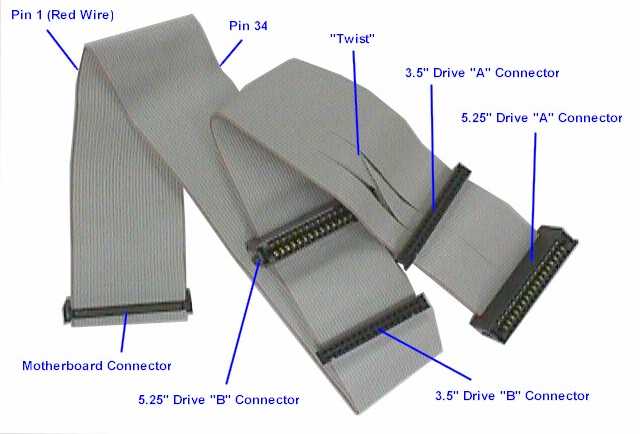
The table explains how the
twisted floppy cable on a "modern" PC is used to perform drive
selection when only two drives are present, the cable between the first and
second drive connectors has pins 10 to 16 reversed
between the connectors. Both drives should be set to an ID of 1,
the drive connected to the first (untwisted) plug would
therefore be Drive 1 (PC Drive "B") and the drive connected to
the second connector, after the twist, would be Drive 0 (PC
Drive "A"). This picture, from
the PC Guide website
shows a typical Universal (supporting both 3.5" and 5.25"
drives) PC floppy cable - a full explanation can be
found on the PC Guide
Floppy
Interface Cable webpage.
Drive Rotational Speed
The details on drive IDs become particularly relevant if you are looking
for a modern drive to replace an original Qume drive. If that is
the case,
another consideration is the rotational speed of the drive. The
data transfer rate between the drive heads and the host
controller is a function of the media density and the rotational
speed of the drive. For the QumeTrak 142, the rotational speed
is 300RPM and the transfer rate is either 125 kbit/s (single
density) or 250 kbit/s (double density).
The rotational speed of the Qume drive is common
to all legacy 360 kb 5.25" drives as well as all 3.5" drives,
but "modern", HD 1.2MB, 5.25" drives have a rotational speed of
360RPM. This potentially means that an older disk controller
would not be able to handle the higher data rate (500 kbit/s)
from a "modern" drive. Some drives, for example most Teak
drives, have a link selectable speed option for 300 or 360RPM,
most newer 5.25" HD drives do not.
If you want to try modifying a 1.2MB, 360RPM
drive to operate at 300RPM,
this page from Dave Duffield how to do it.
|

