|
|
|
|
 |
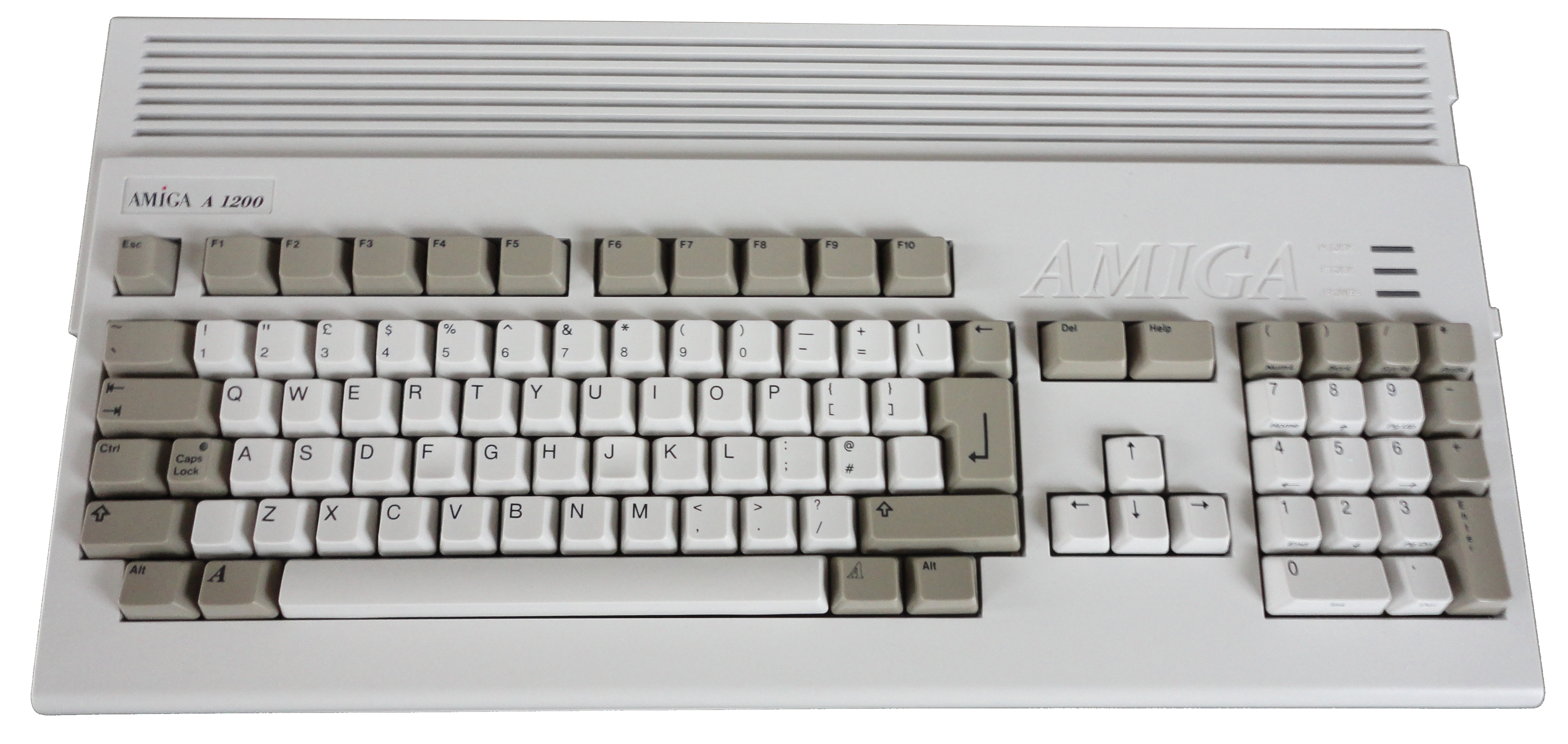
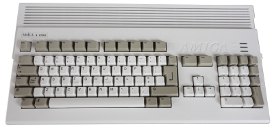
The Commodore Amiga
A1200 |
Floppy Disk Interface Signals
The
Techie Stuff . . . . . .
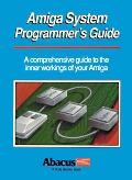 |
The information on this page was extracted from
the "Amiga System Programmer's Guide",
from the Abacus
Amiga series, published by
Data Becker in 1988. This predates the earliest
A1200s by about 4 years, but the information here
should still be accurate for the floppy interface in
an A1200. (There were particular issues with the
Escom A1200's drive interface that are not relevant
to this discussion) |
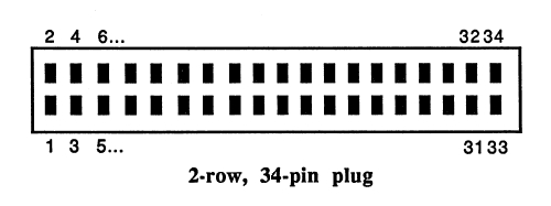
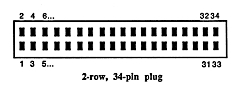
| The motherboard
connector for the internal floppy disk drive is a
34-way, 2-row header plug, with almost exactly the
same pin-out as a Shugart 5.25" drive connector, but
using only the pins necessary to connect to the
internal drive. The Amiga pin-out is as shown below
: |
|
2 |
CHNG |
4 |
INUSE |
|
6 |
(Not used) |
8 |
INDEX |
|
10 |
SEL0 |
12 |
(Not used) |
|
14 |
(Not used) |
16 |
MTR0 |
|
18 |
DIR |
20 |
STEP |
|
22 |
DKWD |
24 |
DKWE |
|
26 |
TK0 |
28 |
WPRO |
|
30 |
DKRD |
32 |
SIDE |
|
34 |
RDY |
|
|
|
All odd numbered pins are connected to
ground |
|
 |
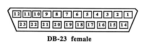
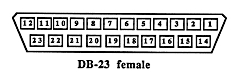
| The Amiga specific
floppy drive external connector supports up to three
external floppy drives, using a 23-way Female
"D" type connector, although still available, they
are not common and can be quite expensive. The
pin-out is as shown below : |
| 1 |
RDY Disk ready |
13 |
SIDE Side selection |
| 2 |
DKRD Read data from disk |
14 |
WPRO Write protect |
| 3 |
Ground |
15 |
TK0 Track 0 indicator |
| 4 |
Ground |
16 |
DKWE Switch to write |
| 5 |
Ground |
17 |
DKWD Write data to disk |
| 6 |
Ground |
18 |
STEP Step the R/W head |
| 7 |
Ground |
19 |
DIR Head Direction |
| 8 |
MTRX Motor on/off |
20 |
SEL3 Select drive 3 |
| 9 |
SEL2 Select drive 2 |
21 |
SEL1 Select drive 1 |
| 10 |
DRES Disk reset |
22 |
INDEX Index signal |
| 11 |
CHNG Disk change |
23 |
+12 Volts |
| 12 |
+5 Volts |
|
|
|
 |
The operation of some of these pins in an Amiga is somewhat
different to that on other floppy interfaces, a description of
their usage in the Amiga are given below.
|
SELx |
The Amiga
uses the SELx line to select one of the four signals
drives.
Except
for the MTRX and
DRES lines, all other signals are
active only when the corresponding
SELx line is
activated. |
|
MTRX |
Normally
this line causes all connected drives to turn their
motors on, however, the Amiga has a flip-flop for
each drive which takes on the value of the
MTRX line
whenever the SEL line for the given drive goes low.
The output of the flip-flop is connected to the MTR
line of the drive. This allows the drive motors to
be turned on and off independently. For example, if
the SEL0 line is placed low while the
MTRX line is
at 0, the motor on the internal floppy turns on. For
the internal drive this flip-flop is on the
motherboard. For each additional drive, an
additional one is needed. On the 1010 disk drive
Commodore placed this flip-flop on a small adapter
board. |
|
RDY |
When the
MTR line of the corresponding drive goes to 0, the
RDY line (ready) signals the Amiga that the drive
motor has reached its optimum speed and the drive is
now ready for read or write accesses. If the MTR
line is 1, so that the drive motor is turned off, it
is used for a special identification mode (see
below). |
|
DRES |
The
DRES
line (Drive RESet) is connected to the standard
Amiga reset and is used only to reset the motor
flip-flop so that all motors are turned off. |
|
DKRD |
The data
from the drive selected by
SELx travels to the Amiga
through the
DKRD line (DisK Read Data) to the
DKRD
line on Paula. |
|
DKWD |
Data from
Paula's
DKWD pin to the current drive, which then
writes it to the diskette. |
|
DKWE |
The
DKWE
line (DisK Write Enable) switches the drive from
read to write. If the line is high, the data are
read from diskette, while if it is low, data can be
written to diskette. |
|
SIDE |
The
SIDE
line selects which side of the diskette the data are
read from or written to. If it is high, side 0 (the
lower read/ write head) is active. If it is low,
side 1 is selected. |
|
WPRO |
The
WPRO
line (Write PROtect) tells the Amiga that the
inserted disk is write-protected. If a
write-protected disk is in the drive, the
WPRO line
is 0. |
|
STEP |
A
positive transition on the
STEP line moves the
read/write head of the drive one track in or out,
depending on the state of the DIR line. The
STEP
signal should be at 1 when the SEL line of the
activated drive if set back to high or there may be
problems with the diskette-change detection. |
|
DIR |
The DIR
line (DIRection) sets the direction in which the
head moves when a pulse is sent on the STEP line.
Low means that the head moves in toward the centre
of the disk and high indicates out toward the edge
of the disk. Track 0 is the outermost track on the
disk. |
|
TK0 |
The
TKO (TracK
0) line is low whenever the read/write head of the
selected drive is on track 0. This allows the head
to be brought to a defined position. |
|
INDEX |
The
INDEX
signal is a short pulse which the drive delivers
once per revolution of the diskette, between the
start and end of a track. |
|
CHNG |
With the
CHNG (CHaNGe) line the drive signals the Amiga that
the diskette has been changed. As soon as the
diskette has been removed from the drive, the
CHNG
line goes low. The line stays low until the computer
issues a STEP pulse. If there is a diskette in the
drive again by this time,
CHNG goes back to 1.
Otherwise it stays at 0 and the computer must issue
STEP pulses at regular intervals in order to detect
when a diskette has been inserted in the drive.
These regular STEP pulses are the cause of the
clacking noises that an Amiga drive makes when no
diskette is inserted. |
|
INUSE |
The
INUSE
line exists only on the internal floppy connector.
If this line is placed low, the drive turns its LED
on. Normally this line is connected to the MTR line. |
To recognize when a drive has been connected to the bus, there
is a special drive identification mode.
A 32-bit word is read serially from the drive. To start this
identification, the MTR line of the drive in question must be
turned on and then off again (The description of the
MTRX line
tells how this is done). This resets the serial shift register
in the drive. The individual data bits can then be read by
placing the SELx line low and reading the value of the
RDY as a
data bit and then placing the
SELx line high again. This process
is repeated 32 times. The bit first received is the MSB
(Most-Significant Bit) of the data word. Since the RDY line is
active low, the data bits must be inverted.
The following are standard definitions for external drives:
- $0000 0000 No drive connected (00)
- $FFFF ffff Standard Amiga 3 1/2" drive (11)
- $5555 5555 Amiga5 1/4" drive, 2x40 tracks (01)
As you can see, there
are currently so few different identifications that it suffices
to readjust the first two bits.
[A high capacity
floppy drive was available for later Amigas, so this list may
have been expanded for later models]
Most standard drives
do not support this option.
As mentioned before, all of the lines except
DRES affect only
the drive selected. Originally the
MTRX line was also
independent of SELx, but the Amiga developers changed this by
adding the motor flip-flop described on the
floppy disk
interfacing page.
|
 |
|
|