Connecting External
"Floppy Drives"
This page discusses how to attach non-Amiga "floppy drives"
to the external floppy connector of an A1200, specifically, the
two emulators that I am considering, the HxC and
Gotek floppy disk drive emulators. The assumption
is that the A1200's internal floppy drive has been retained and
is operating as DF0.
The Gotek emulator, running with version 1.05a
of Hervé
Messinger's Amiga firmware emulates one additional "drive"
operating as DF1. The HxC emulator can potentially emulate up to
2 "drives", at the moment, I have not worked out how to do this,
hopefully I can and will document it here in due course.
Disk drives designed for use in a PC have a number of
differences from Amiga drives and, older drives in particular,
can have a number of jumpers installed to configure the drive's
interaction with the disk controller. In a typical PC drive such
as the Samsung SFD-321B, pin-34 can be configured as either
Disk Change (CHNG)
or Ready (RDY)
, but the Amiga expects to see both signals.
Disk Change Signal,
CHNG
In discussions relating to using a PC floppy disk as an Amiga
drive, various messages on Amiga Forums such as the
English Amiga Board, advise
that the Disk Change signal (CHNG)
from floppy drive pin-34 should be connected to pin-2 of the
internal Amiga floppy connector - this corresponds to pin-11 of
the external connector. Some jumpers have to be added to
most drives so that the Disk Change line works properly. The best source for
this information is the manual for the drive in question. As an
example, jumper Jl has to be shorted on an NEC FC1035.
Drive Ready Signal,
RDY
When the drive motor is turned on (by
MTRX
going low), it will take a small amount of time, say, less than
500ms, to reach its normal operating speed (300/360 RPM), the
Amiga waits for the Ready signal to go low,
indicating that the drive is up to speed,, before initiating
read or write operations. (If the motor signal is high, the
ready signal is used to identify the drive type as described on
my interface signal
description page.)
Drive In Use Signal,
INU
The floppy drive LED can be controlled by the In Use
signal (INU),
which is normally connected to the corresponding motor line,
MTR0
for the internal drive, or
MTR1
to
MTR3 for the external drives. Alternatively,
most drives have jumper options that allow the control signal
for the LED to be set on the drive itself.
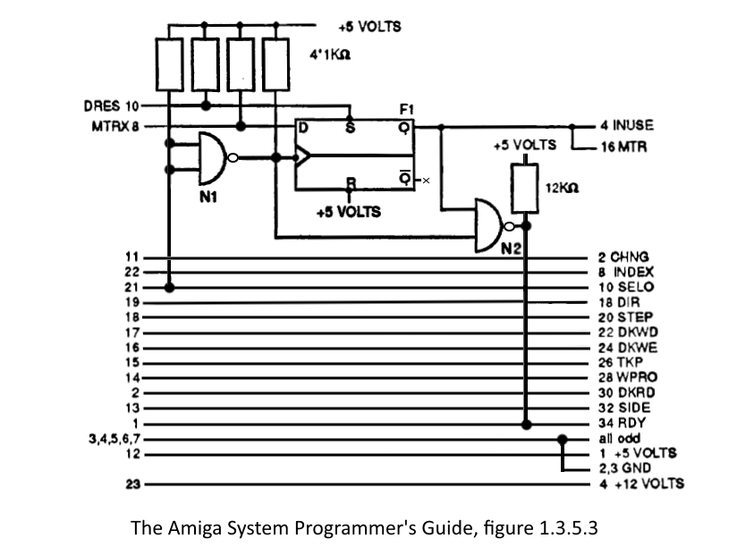
Motor Control
| The Shugart interface includes a single Motor
On (MTRON)
line which would normally cause all connected drives to turn
their motors on, however, the Amiga uses a flip-flop for each
drive which takes on the value of the MTRX line whenever the
SEL
line for the given drive goes low. |
| The output of the
flip-flop is connected to the MTR line of the drive. This allows the drive
motors to be turned on and off independently.
For example, if the SEL0 line is placed low
while the MTRX line is at 0, only the motor on the
internal floppy turns on, the flip-flop for the
internal drive is on the motherboard.
For each additional drive, an additional
flip-flop, external to the Amiga, is needed. In the
case of the 1010 disk drive, Commodore placed this
flip-flop on a small adapter board, for
non-Commodore drives, this logic must be provided by
other means.
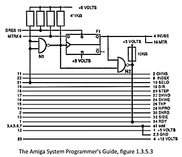
This diagram (a revised/corrected version of Figure
1.3.5.3 from the Amiga System Programmer's Guide),
shows how this can be done. |
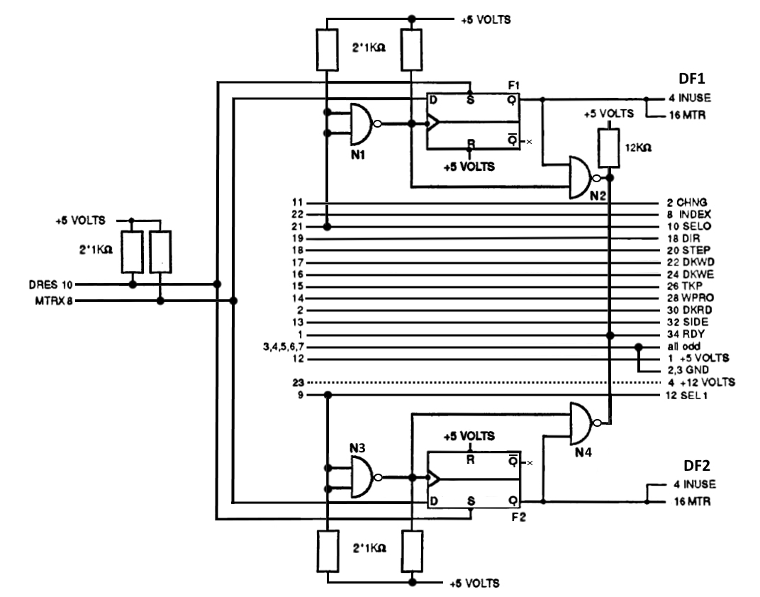
 |
|
In this example, pin-21 (SEL1)
of the Amiga external floppy connector is connected to pin-10 (DS0)
of the floppy drive interface, i.e., the external drive should
be addressed as ID:0. The Fl flip-flop stores the signal on the
MTRX line when the
SEL1 line goes from high to low. Since the
flip-flop stores the value on its data input on the leading edge
of the clock,
SEL1 must be inverted. This is accomplished by the NAND gate
Nl. The Q output is connected directly to the Motor
On input (MTR) of the external drive, as well as
its In Use input (INU)
to set the drive LED.
[The N2 NAND gate is not related to motor control, it is used for
a special drive identification mode
described on my
interface signal description page
Whenever the motor is turned off and the SEL1 line is active
(0), this gate pulls the RDY line low. Thus the Amiga recognises
this drive as a standard 3 1/2" drive with the number DF1:] |
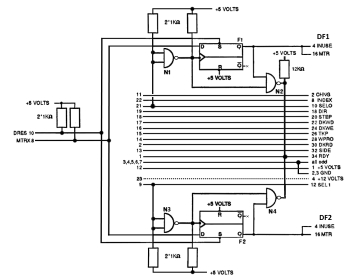
| Since only half of the two IC's required are actually
used, the same components can be used to add a second external drive.
The inputs of N3 must then be connected to
SEL2
(pin 9 on the external drive connector) and the In Use
and Motor
On inputs of the second external drive connected to the
output of flip-flop F2. Floppy drives only
used the +12V supply for the motors, if the
interface is only going to be used for a solid-state
floppy drive emulator, then the +12V line can be
omitted if desired. This would provide protection
against connecting the device power plug the wrong
way around - which is not difficult to do, although
some devices provide their own protection against
this.
Note : the +5V line on the Amiga external floppy
drive port is only rated at 250mA |
 |
Proposed connection for 34-way ribbon cables to drives (no
twist)
| Pin |
Amiga |
I
N
T
E
R
F
A
C
E
B
O
A
R
D
|
Drive A (DF:1) |
Drive B (DF:2) |
Pin |
Comment |
| 1 |
RDY |
(Not used) |
(Not used) |
-- |
Using flip-flops
F1 & F2 |
| 8 |
MTRX |
(Not used) |
(Not used) |
-- |
To flip-flops F1
& F2 |
| -- |
(Not used) |
Density Select |
Density Select |
2 |
(Tie to 0V for
Low/DD) |
| -- |
INU |
(Not used) |
(Not used) |
4 |
(Set by drive
configuration) |
| 20 |
DS3 |
(Not used) |
(Not used) |
6 |
Daisy-chained |
| 22 |
IDX |
INDEX |
INDEX |
8 |
Daisy-chained |
| -- |
(Not used) |
Motor Enable A |
Motor Enable A |
10 |
Using flip-flop
F1 |
| 9 |
DS2 |
Drive Select B |
Drive Select B |
12 |
Daisy-chained |
| 10 |
DRES |
(Not used) |
(Not used) |
-- |
To flip-flops F1
& F2 |
| 21 |
DS1 |
Drive Select A |
Drive Select A |
14 |
Daisy-chained |
| 8 |
MTRX |
Motor Enable B |
Motor Enable B |
16 |
Using flip-flop
F2 |
| 19 |
DIR |
DIR |
DIR |
18 |
Daisy-chained |
| 18 |
STEP |
STEP |
STEP |
20 |
Daisy-chained |
| 17 |
WDATA |
WDATA |
WDATA |
22 |
Daisy-chained |
| 16 |
WGATE |
WGATE |
WGATE |
24 |
Daisy-chained |
| 15 |
TRK00 |
TRK00 |
TRK00 |
26 |
Daisy-chained |
| 14 |
WPT |
WPT |
WPT |
28 |
Daisy-chained |
| 2 |
RDATA |
RDATA |
RDATA |
30 |
Daisy-chained |
| 13 |
SIDE1 |
SIDE1 |
SIDE1 |
32 |
Daisy-chained |
| 11 |
CHNG |
RDY |
RDY |
34 |
Daisy-chained |
| 3, 4, 5, 6, 7 |
All odd-numbered pins are
ground |
Daisy-chained |
Hardware Required
I have seen a couple of interface boards on the internet that
appear to be based on the circuit in the Amiga System
Programmer's Guide , unfortunately both of them only support
the use of a single drive as DF1: Whilst I do not intend to add
to physical drives to my A1200, the ability to support 2 drives
using my HxC emulator is important to me.
Although I tried to get information from one of the sellers
to allow me to modify the board for two drives, he was unwilling
to help or modify a board for me, or create a new version, so it
looks like there is no alternative to making my own - KiCad -
here I come again . . . . .