|
|
|
|
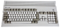 |
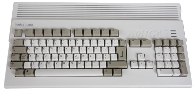
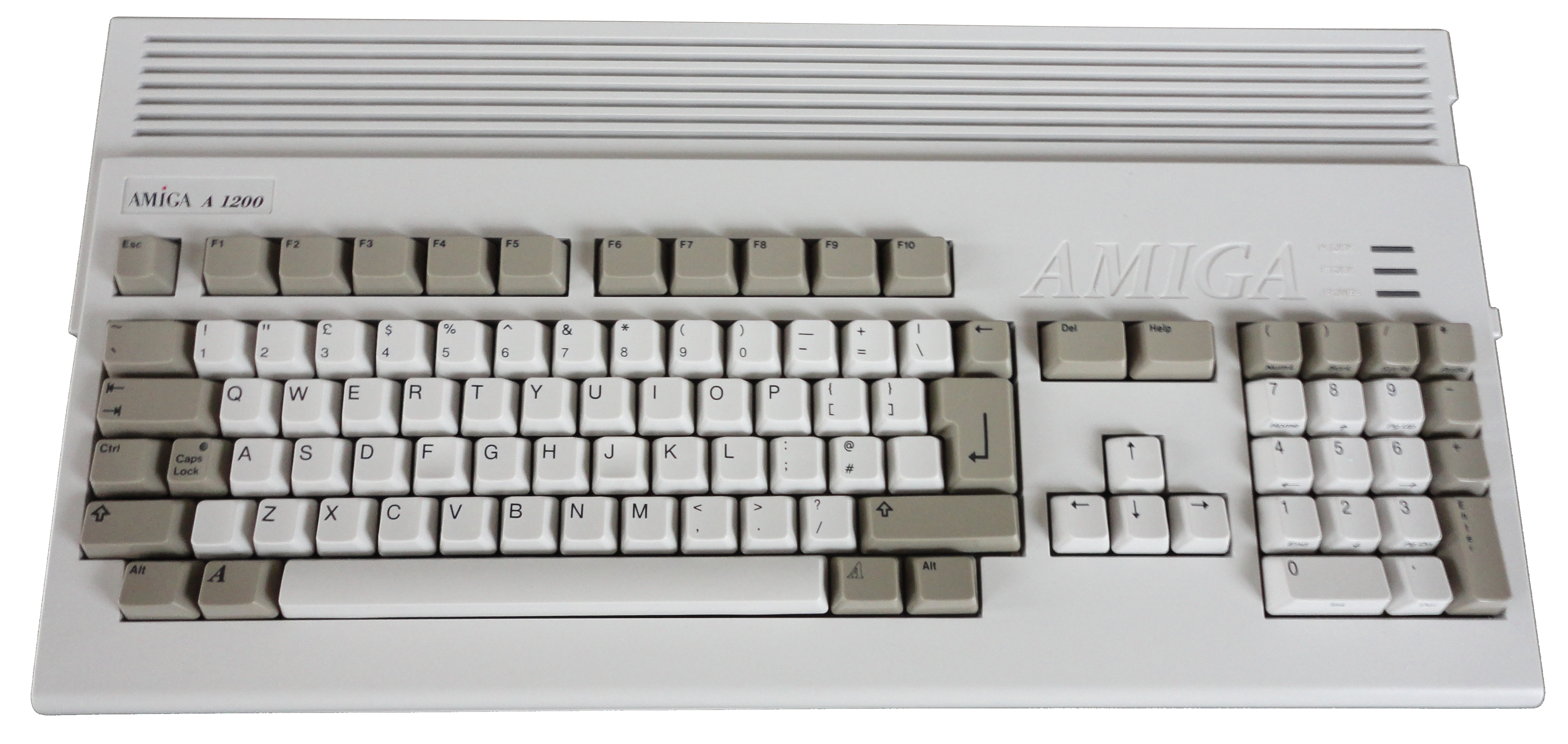
The Commodore Amiga
A1200 |
Storage Upgrade Options
"Floppy Disk" Interfacing
|
Amiga Floppy Drive Characteristics
(Original DS/DD diskette) |
| Drive size |
3.5" |
| Density |
Double (DD) |
| RPM |
300 |
| Data rate |
250 kbit/s |
| Heads |
2 |
| Tracks |
80 |
| Sectors / track |
11 |
| Bytes / sector |
512 |
| Default capacity |
880kB |
The Shugart Interface
Drive ID Selection
The Amiga floppy disk interface is based on
the
Shugart "standard" which supports up to four floppy
drives, selected with four drive selection SELx signals,
where x is the number of the drive to select. The original
Shugart floppy disk drive used jumpers on the drive to set
its address which would respond to commands to its address
using controller pins 6, 10, 12 & 14. Most "modern" drives,
particularly 3.5" drives for PCs, do not have ID jumpers and are
factory configured to have an ID of 1. (It makes for quicker
assembly when the drives do not need to be individually set up
by the PC manufacturer.)
| Pin |
Name
(Amiga) |
Dir1 |
Description
(Original Shugart Interface) |
Amiga
Pin
(Int.) |
Amiga
Pin
(Ext.) |
Modern PC
Interface3 |
| Pin |
Description |
| 2 |
REDWC |
 |
Reduced Write Compensation
(8") / Density4 |
--- |
--- |
2 |
Density Select |
| 4 |
INU |
|
In Use (non-Shugart) |
4 |
--- |
4 |
(Not used) |
| 6 |
DS3 |
|
Device Select 32 |
--- |
20 |
6 |
(Not used) |
| 8 |
IDX |
 |
Index (generated by the index
hole in the disk) |
8 |
22 |
8 |
(As Shugart) |
| 10 |
DS0 |
|
Device Select 02 |
10 |
--- |
10 |
Motor Enable A |
| 12 |
DS1 |
|
Drive Select 12 |
--- |
21 |
12 |
Drive Select B |
| 14 |
DS2 |
|
Device Select 22 |
--- |
9 |
14 |
Drive Select A |
| 16 |
MTRON |
|
Motor On |
16 |
8 |
16 |
Motor Enable B |
| 18 |
DIR |
|
Direction (of travel of the
head stepper motor) |
18 |
19 |
18 |
(As Shugart) |
| 20 |
STEP |
|
Step |
20 |
18 |
20 |
(As Shugart) |
| 22 |
WDATA |
|
Write Data |
22 |
17 |
22 |
(As Shugart) |
| 24 |
WGATE |
|
Floppy Write Enabled |
24 |
16 |
24 |
(As Shugart) |
| 26 |
TRK00 |
|
Track 0 |
26 |
15 |
26 |
(As Shugart) |
| 28 |
WPT |
|
Write Protect |
28 |
14 |
28 |
(As Shugart) |
| 30 |
RDATA |
|
Read Data |
30 |
2 |
30 |
(As Shugart) |
| 32 |
SIDE1 |
|
Head Select |
32 |
13 |
32 |
(As Shugart) |
| 34 |
RDY |
|
Ready (non-Shugart) / Disk Change |
34 |
1 |
34 |
Disk Change6 |
|
Amiga Specific Pin Usage |
| |
DRES |
|
Disk Reset5
(Used to turn the motors off) |
/RESET |
10 |
|
|
| |
CHNG |
|
Disk Removed From Drive |
2 |
11 |
|
|
| |
|
|
+5 Volts DC (250 mA max) |
+5 Volts |
12 |
|
|
| |
|
|
+12 Volts DC (160 mA max, 540
mA surge |
+12 Volts |
23 |
|
|
| |
|
|
Ground |
Ground |
3, 4, 5, 6, 7 |
|
|
All odd numbered pins in the Shugart
"standard" are
connected to ground, the internal connector follows
this For a more complete description
of the operation of the Amiga floppy disk interface,
see my more detailed
"techie"
page |
|
Notes : |
|
1. Direction
indicates that the signal direction is from the
controller to the drive and vice versa |
|
2. Legacy drives from
different manufacturers may have ID select numbered
either 0 to 3 or 1 to 4 |
|
3. A PC Floppy Disk interface
only supports the use of two drives |
|
4. Pin 2 in the Shugart
interface was originally used for 8" drives that required
different levels of write
pre-compensation as the head moved closed to the
centre of the disk, usually at track 43 (out of 77).
For more modern PC drives, it was used to select the
density of the media in the drive. |
|
5. The DRES line (Drive RESet)
is connected to the standard Amiga reset and is used
only to reset the motor flip-flop so that all motors
are turned off. |
|
6 I don't think this is actually
used on a PC |
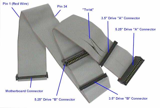
The table
shows how the
twisted floppy cable on a "modern" PC is used to perform drive
selection when only two drives are present, the cable between the first and
second drive connectors has pins 10 to 16 reversed
between the connectors. Both drives should be set to an ID of 1,
the drive connected to the first (untwisted) plug would
therefore be Drive 1 (PC Drive "B") and the drive connected to
the second connector, after the twist, would be Drive 0 (PC
Drive "A"). This picture, from
the PC Guide website
shows a typical Universal (supporting both 3.5" and 5.25"
drives) PC floppy cable - a full explanation can be
found on the PC Guide
Floppy
Interface Cable webpage.
Since the Amiga already has a built-in disk drive, the SEL0
line is connected to the built-in drive and only the SEL1,
SEL2
and SEL3 lines are available on the external drive connector.
References :
Amiga System Programmer's Guide, from the
Abacus Amiga series,
published by
Data Becker in 1988.
|
 |
|
|