|
 |
The Memotech MTX Series |
 |
The FDX 80 Column Graphics Card
Introduction
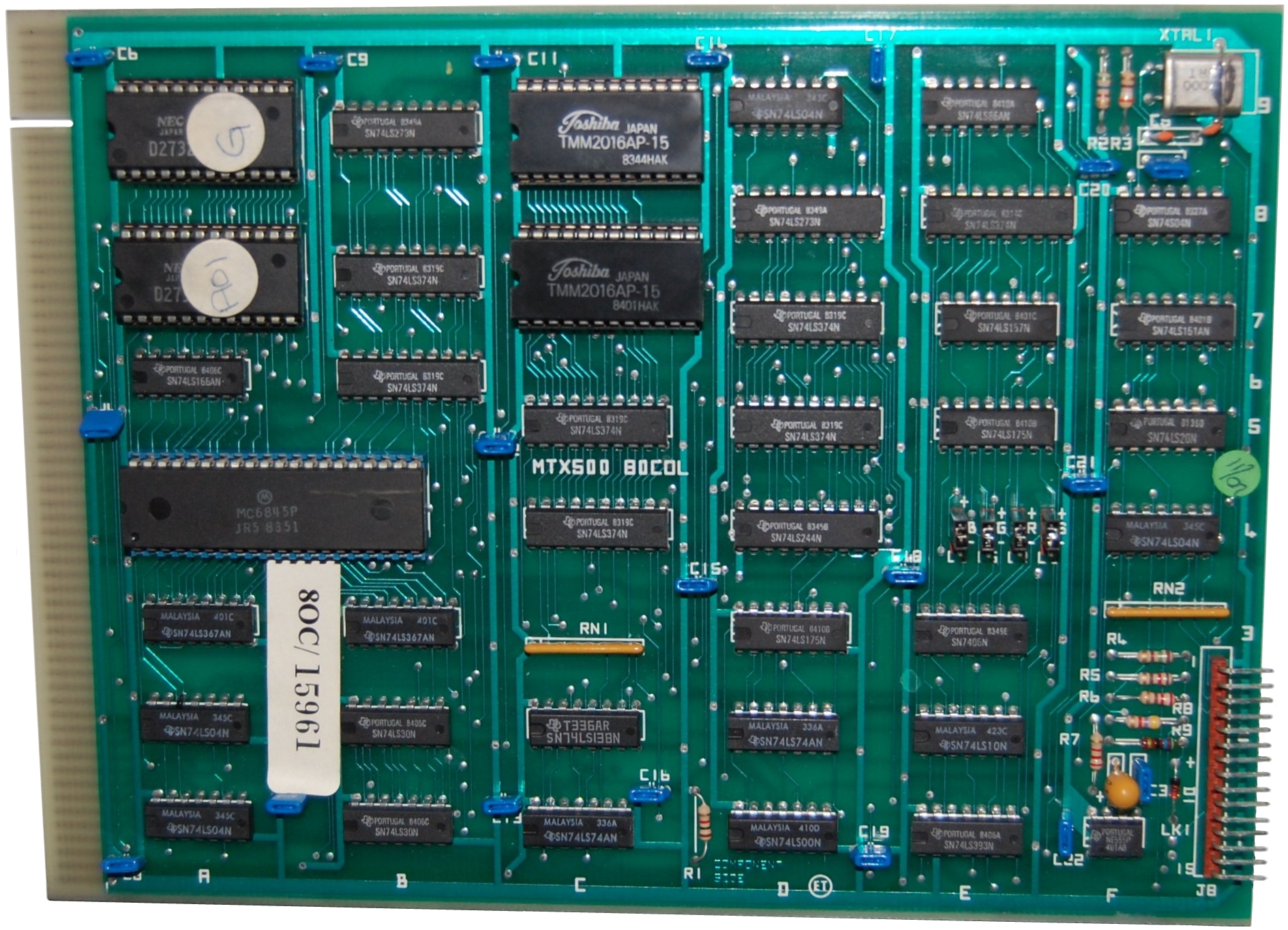
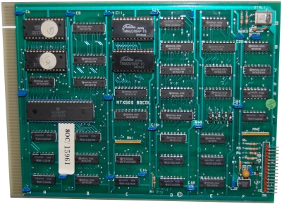
The 80 Column (80C) board in the
FDX is built around a
Motorola
MC6845 Cathode Ray Tube Controller (CRTC). The 6845
was designed to provide the interface between a microprocessor
and raster-scan
CRT displays, it generates the necessary signals to interface
with the display, but does not generate the
pixels themselves.
It generates horizontal and vertical sync signals and supplies
the memory address from where the next pixel should be
generated.
The notes on these pages were written in the context of my trying
to understand the design of the Memotech FDX 80 column card to
help me
find a fault on one of mine. Most of the CRTC notes should be common to other systems using
the 6845, but some points are specific to the Memotech
implementation. The details on these pages are only intended to
provide an overview of the 6845 operation, for an in depth
discussion of the chip, refer to the
MC 8645 datasheet.
The information on these pages is likely to apply equally well
to the display generation portion of the combined 80 Column and
serial card used in MTX512 Series 2 computers.
Originally intended to be a single page summarising the FDX 80
Column card design, the content has grown to the point where it
is better split across a number of pages, use the
navigation links at the bottom of the
pages to move between related pages.
Raster Scan Displays (See the
MTX Video Page for more
detail)
In a raster scan display, the screen is divided into
a number of horizontal scan lines and each pixel on a given line
is illuminated, or not, depending on the characters being
progressively built up. Only 1 pixel is actively
illuminated at any point in time, other pixels may appear to be
illuminated due to the
persistence of the phosphor display; until the electron beam
returns to the same coordinates, the brightness of the pixel
will gradually reduce until the pixel is refreshed, but this is
usually not noticeable by the user.
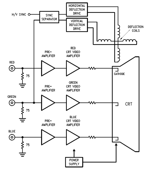
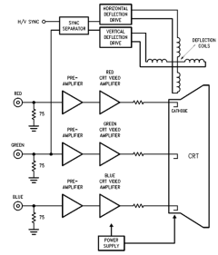
| Conventional displays use a Cathode Ray Tube (CRT),
a simplified block diagram of an RGB monitor is
shown here. A heating element heats the cathode,
causing it to emit electrons which are accelerated
by the electric field of the anode and focused on
a phosphor screen by means of high voltage grids
(not shown). The
negatively charged electrons are deflected by electrical fields
generated by voltages at the deflection plates, in
this way scan lines are formed. An image (raster) is displayed
by scanning the electron beam across the screen.
The screen is coated with a fluorescent material
which illuminates when the fast electrons emitted by
the cathode hit it. Since the phosphor’s luminance
begins to fade after a short time, the image needs
to be continually refreshed. |
 |
One line of picture elements (pixels)
is drawn from left to right in turn, the display is built up
as subsequent lines are drawn from the top to the bottom of
the screen.
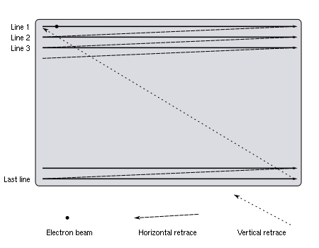
The horizontal synchronisation pulse (HSYNC) separates the
scan lines. The horizontal sync signal is a single short
pulse that usually indicates the start of the line and the rest of
the is drawn after it. Horizontal retrace
means that the electron beam has reached the right hand end
of a row – then it must return to the beginning of the next
scan line. The vertical
synchronisation pulse (VSYNC) separates the video fields
(frames). Vertical retrace means that the
electron beam has reached the lower right hand corner of a row –
then it must return to the upper left corner. The frequency of the vertical sync can therefore
be much lower than that of the horizontal sync. Usually, the
frame rate is matched to the power line frequency (50Hz or
60Hz) which prevents the display from "weaving". Probably the most common sync systems are
separate sync and composite sync.
As its name suggests, separate sync uses separate wires for
horizontal and vertical synchronization. When used in RGB
connections, five separate signals are sent (Red, Green,
Blue, H-Sync, V-Sync). Composite sync combines the
horizontal and vertical synchronization signals onto one
pair of wires. When used in RGB connections, four separate
signals are sent (Red, Green, Blue, Sync).
The maximum rate that a monitor can refresh
the screen is measured in Hertz (cycles/second) and is
called the vertical refresh rate (or vertical scan rate).
The horizontal scan rate is the number of times that the
monitor can move the electron beam horizontally across the
screen, then back to the beginning of the next scan line in
one second. Most early monitors were fixed
frequency e.g, the IBM CGA 5153 monitor had a horizontal
sync rate of 15.85 kHz and a vertical refresh rate of 60.5
Hz, these frequencies are compatible with the FDX 80 Column
card output.
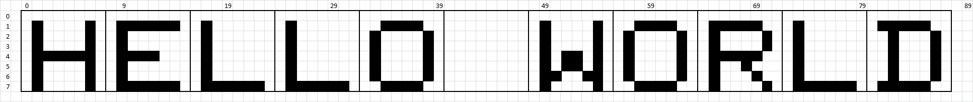
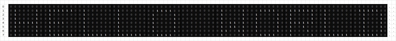
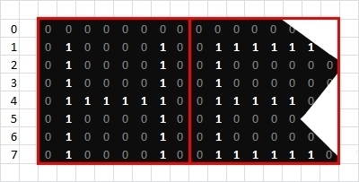
Raster Scanning Example
For example, consider a system where each ASCII character is displayed
using an 8 x 8 matrix
of pixels. To allow for white space between the characters and
rows, the character set could be formed from a matrix of 7 x 6 pixels. A portion of 1 character line
from such a system, comprising of 8 scan
lines is illustrated below :

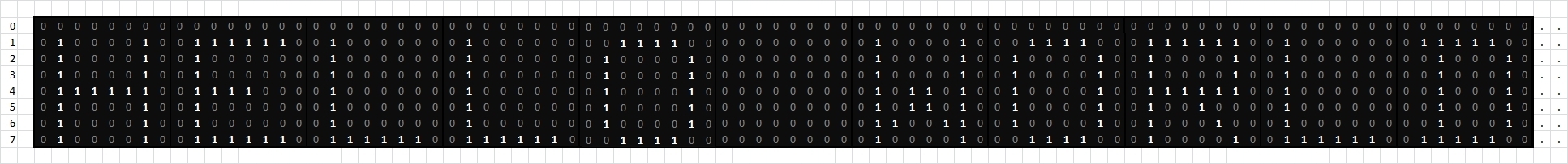
If "0" is used to represent a pixel being OFF and "1" for
it being ON, it can be visualised as shown :
|
 |
| |
| 0 |
0 |
0 |
0 |
0 |
0 |
0 |
0 |
0 |
0 |
0 |
0 |
0 |
. |
. |
. |
. |
. |
| 0 |
1 |
0 |
0 |
0 |
0 |
1 |
0 |
0 |
1 |
1 |
1 |
1 |
1 |
1 |
. |
. |
. |
| 0 |
1 |
0 |
0 |
0 |
0 |
1 |
0 |
0 |
1 |
0 |
0 |
0 |
0 |
0 |
0 |
. |
. |
| 0 |
1 |
0 |
0 |
0 |
0 |
1 |
0 |
0 |
1 |
0 |
0 |
0 |
0 |
. |
. |
. |
. |
| |
| As far as the display electronics are concerned,
each scan line is just a continuous bit
stream of 80 x 8, i.e., 640 bits used to
turn the relevant pixels ON or OFF. |
|
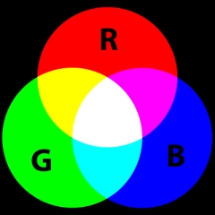
Colour Displays
| This neat diagram from
Wikipedia, shows in graphical form, how 8
colours, or rather, 7 + Black, can be produced from the three primary
colours (Red, Green and Blue). As the image
shows, on an 8 colour RGB system, Cyan for
example is generated by combining Blue and Green.
To display colour images on a raster scan CRT, three
electron beams are required for each pixel, one for
each of the RGB colours and the perceived colour of
the pixel
results from
additive colour mixing. |
 |
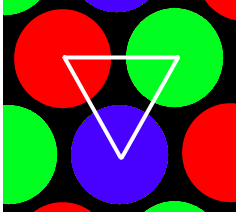
| The coloured dots do not overlap on the CRT, but
are very close to each other. When viewed at normal
viewing distance, the human eye cannot distinguish
them and the three dots are perceived as a mixture
of the three colours.
The FDX 80C card is limited to the 8 colours
available from mixing the three primary colours as
shown above. The IBM Colour Graphics Adapter (CGA)
could set each colour beam to two brightness levels
(in addition to off), which enabled CGA to support
16 colours, i.e., the 8 colours at two levels of
brightness. |
 |
<
Previous
Page Goto
Next
Page >
The
Motorola MC6845
References :
|